Abstract
Two sequential transformations of the orientational structure in nematic liquid crystal droplets containing a dendrimer additive (nanosized macromolecules with light-absorbing azobenzene terminal moieties) under light irradiation in the UV–blue spectral range were investigated. The origin of these transitions is in the change of the boundary conditions due to photoisomerization of the dendrimer adsorbed onto the liquid crystal–glycerol interface. It was shown that the photoisomerization processes of dendrimer molecules in a liquid crystal are accompanied by a spatial rearrangement of their azobenzene moieties, which is the key point in the explanation of the observed effects.
Introduction
Azobenzene compounds represent a very convenient tool for the development of photosensitive materials [1-4]. This feature is associated with the capability of these molecules to change their shape due to absorption of light. A stable trans isomer can be excited by a light quantum and transformed into the metastable cis form, and vice versa, the cis isomer after light excitation returns into trans form. The anisotropic interaction of azobenzene molecules with each other, as well as with their environment, essentially depends on their shape (rod-like for trans isomers and having no distinct anisometry for cis isomers). This leads to the modification of physical properties of different kinds of soft matter, such as light-driven polymers [5,6], elastomers [7-9] microgel particles [10,11], micelles [12,13], nematic liquid crystals (NLCs) [7,14], liquid-crystalline (LC) polymers [15-18] and Langmuir–Blodgett films [19,20] with light-controllable supramolecular structures.
Among the variety of different materials containing azobenzene derivatives, there is special interest in host–guest systems consisting of a mesophase matrix and a small concentration (<1 wt %) of dopant. In particular, they reveal higher optical nonlinear response [14,21]. Some kinds of the polymer dopants, such as a dendrimer with azobenzene terminal moieties [22,23] or a comb-shaped polymer with H-bonded side-chain azobenzene fragments [24,25], can induce the homogeneous orientation of NLC films. These polymer additives are usually adsorbed onto the cell substrates and provide homeotropic anchoring of the NLC film. The boundary conditions can be changed to planar and then return to homeotropic again by photoisomerization processes. The effects of NLC film orientation are very similar to the bulk mediated photoalignment [26,27], which are influenced by exchange of the dopant between the surface and the bulk.
Recently, it was shown that NLC photo-orientation due to the azobenzene dopant photoisomerization can also occur at the interface between nematic and isotropic liquid [28]. It is known [29] that NLC microdroplets in the bulk of glycerol usually have bipolar orientational structure with two boojum defects (Figure 1a). As shown in [28], an azodendrimer additive incorporated into NLC droplets initiates the formation of homeotropic boundary conditions, at which the director orientation of the NLC droplets is radial (Figure 1b). It was assumed that the molecular branches of the adsorbed dendrimer molecules are mostly oriented perpendicularly to the NLC–glycerol interface and align the NLC molecules in the same direction. The UV irradiation causes the trans→cis isomerization of the dopant, the cis isomers of the terminal moieties provide the planar alignment of NLC.
![[2190-4286-9-81-1]](/bjnano/content/figures/2190-4286-9-81-1.png?scale=2.0&max-width=1024&background=FFFFFF)
Figure 1: Sketch of a glass cell with NLC droplets embedded into glycerol with planar (a) and homeotropic (b) boundary conditions. The NLC director distribution in the droplet resting on the solid substrate (1) and in the spherical droplet in the bulk of glycerol (2) are shown by dashed lines. Adapted from [30], with the permission of AIP Publishing.
Figure 1: Sketch of a glass cell with NLC droplets embedded into glycerol with planar (a) and homeotropic (b)...
In our experiment reported as communication in [30], the NLC was doped with a carbosilane dendrimer of the fifth generation. The obtained results appeared to be different from the ones mentioned above. The presence of the azodendrimer additive used in the experiment did not influence the orientational structure of NLC droplets, i.e., with or without dopant the NLC director distribution of microdroplets was bipolar. However, under near-UV light illumination, the bipolar orientation of NLC droplets changed to a radial orientation.
In addition, the photoinduced change in the NLC director distribution was observed in the droplets resting on the solid substrate [30]. The NLC director distribution with boojum defect on the top of the droplet (Figure 1a) can be reversibly changed to almost homeotropic NLC alignment (Figure 1b). The interest in these geometries of NLC droplets is explained by their better stability in comparison with the droplets in the bulk of the solvent. Consequently, they are more promising for some applications such as the detection of different chemical compounds [31-33].
In this paper, we present new experimental data for NLC droplets in glycerol showing a sequence of reversible photoinduced orientational transitions caused by the isomerization of dendrimer dopant under light illumination with different wavelengths. Both NLC droplets in the bulk of glycerol and in contact with the solid substrate are considered. To understand the nature of these transitions, the spatial configuration of dendrimer molecules in the nematic matrix is considered. We elaborate a method for estimation of the orientational order parameter of the azobenzene fragments in a nematic matrix at different percentages of isomers.
Results and Discussion
Orientational structure modulation in NLC droplets
NLC droplets in the bulk of glycerol
Structural transformations were investigated for the droplets of NLC doped with the azobenzene dendrimer (G5) in glycerol environment. The microdroplets (with diameter d ≈ 30 μm) of NLC in the bulk of glycerol have the same bipolar structure with two point defects on the droplet surface as the undoped NLC (Figure 2a). The director distribution of NLC droplets is determined by planar surface conditions in glycerol. Thus, the presence of polymer additive does not disturb the orientational structure of the droplets in the absence of light-emitting diode (LED) illumination.
![[2190-4286-9-81-2]](/bjnano/content/figures/2190-4286-9-81-2.png?scale=2.0&max-width=1024&background=FFFFFF)
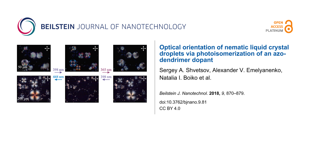
Figure 2: POM images of NLC droplet structures in the bulk of glycerol obtained at light-emitting diode irradiation with wavelengths of (a) 448 nm, (b) 398 nm and (c) 365 nm. The arrows show the direction of transitions. The double arrows show the directions of the crossed polarizers.
Figure 2: POM images of NLC droplet structures in the bulk of glycerol obtained at light-emitting diode irrad...
The LED illumination with λmax = 398 nm causes a bipolar-to-radial orientational transition in NLC droplets due to the change in the boundary conditions from planar to homeotropic (Figure 2a,b). The same orientational structures were formed under light of λmax = 406 nm. The subsequent light illumination with λmax = 448 nm (or 422 nm, or 466 nm) restores the initial bipolar structure (Figure 2a). These structure transformations were first described in our communication [30].
After the light irradiation with λmax = 398 nm, the irradiation with light of λmax = 365 nm (as well as of λmax = 384 nm) tends to turn the radial structure of the droplets to the one (Figure 2c) that is close to the initial bipolar structure (Figure 2a). The NLC droplet orientation is caused by planar anchoring conditions or anchoring conditions tilted at a small angle [34,35].
It is possible to induce the orientational transitions in the opposite direction. For instance, the NLC structures shown in Figure 2c transform into those presented in Figure 2b under light irradiation with λmax = 398 nm (or 406 nm), while the structures shown in Figure 2b transform into the ones presented in Figure 2a under light irradiation with λmax = 448 nm (or 466 nm). In each case, the formation time of stable orientational structures in NLC droplets varies from several to several tens of seconds depending on the droplet size.
The orientational structures obtained by light irradiation can spontaneously transform into the initial state in the absence of LED illumination. The bipolar droplet structure shown in Figure 2c first relaxes to radial (Figure 2b) over a time of approximately 5 min and then, over a time of 20 min, the droplets return back to a bipolar structure (Figure 2a).
Thus, the NLC droplets can consequently change their configuration twice when the wavelength of the irradiation light is decreased. These transformations of NLC droplets strongly depending on the light wavelength can be explained by changing concentrations of trans and cis isomers of the dendrimer azobenzene moieties.
NLC droplets in contact with the solid substrate
Let us consider the orientational transitions of NLC droplets resting on the cell substrate. Before any LED irradiation, the NLC droplets exhibit homeotropic alignment on the substrate coated with an orienting compound and planar alignment on the glycerol interface. This leads to the director distribution with one bujoom defect on the top (Figure 1a). These droplets are visualized in crossed polarizers as slightly twisted Maltese crosses, while the smaller droplets between them are the previously described droplets in the bulk of glycerol (Figure 3a). A twist can be explained by the difference between elastic splay and twist constants (K11 and K22) [36] or/and a contribution of the elastic constant K24 [37] to the energy. The breadth of droplets D varies from 15 to 250 μm. By measuring the droplet size before and after adsorption, we evaluated the average ratio of a droplet height h to its length D, which equals 0.2.
![[2190-4286-9-81-3]](/bjnano/content/figures/2190-4286-9-81-3.png?scale=2.0&max-width=1024&background=FFFFFF)
Figure 3: POM images of NLC droplet structures in contact with the solid substrate obtained under light-emitting diode irradiation with wavelengths of (a) 448 nm, (b) 398 nm and (c) 365 nm. The arrows show the direction of transitions. The double arrows show the directions of the crossed polarizers.
Figure 3: POM images of NLC droplet structures in contact with the solid substrate obtained under light-emitt...
The LED illumination causes the same changes in the boundary conditions of the NLC droplets with glycerol as in the case of spherical NLC droplets in the bulk of glycerol described above. Namely, the influence of light of λmax = 398 nm (or 406 nm) leads to homeotropic boundary conditions with glycerol (Figure 1b), and the droplet structure becomes almost homogeneous with the director being preferably oriented normally to the substrate and visualized as dark regions (Figure 3b). The UV illumination with λmax = 365 nm (or 384 nm) provides the boojum defect formation due to planar (or close to planar) anchoring of NLC with glycerol (Figure 3c). The reverse changes from planar to homeotropic anchoring of NLC with glycerol can be produced by light irradiation with λmax = 398 nm (or 406 nm), and then, from homeotropic to degenerated planar anchoring, by light irradiation with λmax = 448 nm (or 422 nm, or 466 nm). Note that the photoinduced transitions between the initial, with one boojum, and the structure free from point defects (Figure 3a,b) were first obtained in [30].
Orientational transitions in NLC droplets resting on the substrate can also occur spontaneously in the same manner, as in the droplets in the bulk. After 365 nm illumination, the orientational structure with one bujoom (see Figure 1a and Figure 3c) becomes almost homeotropic over a time of about 5 min (see Figure 1b and Figure 3b) and finally, over a time of 20 min, the bujoom defect is formed again (see Figure 1a and Figure 3a).
Interpretation of photoinduced orientational transitions
Summarizing the obtained results for the orientational transitions in spherical NLC droplets and in the droplets in contact with the solid substrate, we can conclude that the change of the boundary conditions is associated with the variation in isomer concentrations of dendrimer terminal moieties. To clarify the influence of these concentrations on the NLC–glycerol boundary conditions, we need to consider the spatial configuration of the G5 dendrimer.
It is known [38] that the terminal moieties with flexible spacers can pack loosely with respect to each other without coiling. The existence of smectic and columnar mesophases of pure G5 dendrimer, as well as large absorption dichroism [39] of G5 dendrimer dissolved in NLC, clearly shows that the dendrimer branches can be oriented in some direction due to molecular interaction. In contrast, the formation of bend cis isomers significantly reduces the excluded volume of the macromolecule and disturbs the arrangement of the terminal moieties.
Considering NLC droplets, we can suggest that a layer of the adsorbed dendrimer macromolecules at the NLC–glycerol interface works as a command surface [26]. When a significant amount of isomers exists in the rod-like trans state, they are oriented along the NLC director n and do not influence the NLC orientation in contact with glycerol. The orientation remains degenerated planar as without dendrimer (Figure 4a). Note that the dendrimer moieties do not penetrate into glycerol due to their hydrophobic properties.
![[2190-4286-9-81-4]](/bjnano/content/figures/2190-4286-9-81-4.png?scale=2.0&max-width=1024&background=FFFFFF)
Figure 4: Schematic illustration of dendrimer molecules near the NLC–glycerol interface and of the NLC director n (a) when all azo moieties of the dendrimer are in trans state, (b) when the concentration of trans isomers is comparable to the concentration of cis isomers, (c) when almost all isomers exist in the cis state.
Figure 4: Schematic illustration of dendrimer molecules near the NLC–glycerol interface and of the NLC direct...
Under light irradiation, the azobenzene fragments partially transform into the bent cis isomers having a very small order parameter in the nematic matrix [40]. In the case of azobenzene monomers (M), the order parameter of the cis isomers, Scis, equals ca. 0.1, which is much smaller than the order parameter of the nematic matrix. In our case, Scis should be further reduced by the disturbance of dendrimer molecular branches, and thus, can be neglected.
In the environment of disordered cis isomers, the trans isomers are oriented radially with respect to the dendrimer molecule center (Figure 4b). On the macroscopic level, the order parameter of the trans isomers should be zero. The NLC molecules tend to be oriented along the nearest trans isomers of dendrimer molecules forming a layer at the interface. As a result, the NLC director is aligned homeotropically at the interface. A similar situation, in which NLC molecules are ordered in the vicinity of nanosized particles, was considered in [41]. However, if the most of azo moieties are converted into the cis isomer under UV irradiation, they provide a degenerated planar orientation of NLC at the interface (Figure 4c).
It is also possible to explain the orientational structure transitions obtained in NLC microdroplets containing azodendrimers of the third generation considered in [28] in the same terms. If the molecular branches of the dendrimers are much shorter than in our case, before irradiation, the trans isomers can be ordered along the radius of each dendrimer molecule and cause the homeotropic anchoring at the NLC–glycerol interface. Under UV irradiation, almost all azofragments are converted to cis isomers, which provide the degenerated planar orientation. This situation is similar to the transition observed in our case (Figure 2b,c).
Influence of photoisomerization on the order parameter of the trans isomer
To prove the described concept, we have clarified experimentally how the formation of cis isomers affects the order parameter of trans isomers of the G5 dendrimer and also of the azobenzene monomer (M), which is similar to the G5 terminal moieties, incorporated into the nematic matrix. To this end, we used the spectroscopic method that is described in the Experimental section.
The polarized absorption spectra of planar cells with NLC doped with M or G5 were measured before and after LED irradiation (Figure 5). The decrease of the light wavelength leads to a sequential reduction of the absorption near the absorption band of the trans isomer (about 365 nm). At the same time, the dichroism D = (αe − αo)/(αe + αo) of the samples is also reduced. The reduction of D is larger for the G5-doped NLC than for the M-doped NLC. For example, after LED illumination with λmax = 406 nm, the dichroism D is equal to 0.8 for M-doped NLC and 0.1 for G5-doped NLC. This difference can be explained by the higher concentration of cis isomers or by the reduction of the trans isomer order parameter, Strans.
![[2190-4286-9-81-5]](/bjnano/content/figures/2190-4286-9-81-5.png?scale=2.0&max-width=1024&background=FFFFFF)
Figure 5: Absorption spectra of the extraordinary (solid curves) and ordinary (dashed curves) waves for (a) NLC doped with monomer M and (b) NLC doped with dendrimer G5 before and after LED illumination with λmax = 365, 384, 398, 405, 422, 448 and 466 nm.
Figure 5: Absorption spectra of the extraordinary (solid curves) and ordinary (dashed curves) waves for (a) N...
The obtained data allow one to estimate the trans isomer order parameter and the ratio of isomers under varying LED irradiation. First, the cis isomer absorption coefficient should be determined. It is convenient to use the spectra after LED illumination with λmax = 365 and 398 nm due to relatively large absorption coefficients and difference in spectral dichroism. Using the procedure described in the Experimental section, for the NLC doped with monomer M, we have found the relative concentrations of cis isomers Xcis = 0.90 at λmax = 365 nm and Xcis = 0.74 at λmax = 398 nm, while the absorption coefficient at λ = 365 nm was found to be αcis = 6 cm−1. For the G5-doped NLC, we have found Xcis = 0.93 at λmax = 365 nm, Xcis = 0.81 at λmax = 398 nm, and αcis = 10 cm−1 at λ = 365 nm. Then, we obtain the dependence of the trans isomer order parameter, Strans, on the cis isomer concentration, Xcis, induced by the other light sources (Figure 6).
![[2190-4286-9-81-6]](/bjnano/content/figures/2190-4286-9-81-6.png?scale=2.0&max-width=1024&background=FFFFFF)
Figure 6: The trans isomer order parameter, Strans, as a function of the relative concentration of cis isomers, Xcis, for (1) NLC doped with monomer M and (2) NLC doped with dendrimer G5.
Figure 6: The trans isomer order parameter, Strans, as a function of the relative concentration of cis isomer...
The change in light wavelength λmax from blue to UV causes a monotonous increase of cis isomer concentration of both azobenzene compounds M and G5. From Figure 6 it follows that, in the case of monomer dopant M (Figure 6, upper red curve), the trans isomer order parameter, Strans, almost remains unchanged with the variation in cis isomer concentration, Xcis. Since the Strans is supposed to be close to the NLC order parameter [40], we can conclude that the formation of cis isomers does not affect the order parameter of the nematic matrix up to Xcis ≈ 0.8. A small reduction of Strans at Xcis > 0.8 generally means that the nematic order parameters of trans isomers and nematic matrix can be influenced directly by the presence of cis isomers to a very small extent. On the contrary, for the NLC doped with dendrimer G5, the monotonous increase of Xcis is accompanied by a dramatic decrease of Strans (Figure 6, lower black curve). This reduction is not associated with the change in NLC order parameter and can be explained by a rearrangement of trans isomers surrounded by disordered cis isomers.
Let us now return to the description of photoinduced transitions in the NLC droplets with dendrimer additive. The obtained data for Strans, under LED irradiation match the proposed concept of light-induced effects in NLC droplets (described in the section above). Under LED irradiation with λmax = 422, 448 or 466 nm (or without any LED irradiation), Strans is relatively large (Strans ≥ 0.3 at Xcis < 0.4), and the dendrimer azobenzene moieties are oriented mostly along the NLC director. Thus, the dendrimer additive does not influence the degenerated planar NLC orientation (Figure 2a and Figure 3a). Under LED irradiation with λmax = 398 or 406 nm, a significant amount of cis isomers is formed. This leads to a reduction of trans isomer order parameter (Strans < 0.3 at 0.4 < Xcis < 0.8), and the NLC director becomes oriented normally to the NLC–glycerol interface (Figure 2b and Figure 3b). Finally, when almost all azo moieties are in the cis state (Strans < 0.1 at Xcis > 0.8) under illumination with λmax = 384 or 465 nm, the orientation of NLC director becomes planar (Figure 2c and Figure 3c).
If the NLC is doped with azobenzene monomers (M), the trans isomers are always oriented along the NLC molecules and unable to change the director orientation, which was proved experimentally [30], where it was shown that the orientational structure does not change under LED illumination in NLC droplets containing the low-molar-mass azobenzene additives. It should be mentioned that this statement is correct only at relatively small concentrations of azobenzene monomer, when the dopant barely influences the NLC ordering. If the amount of azo compound is large, the change in the isomer concentration can greatly affect the properties of the NLC system. For instance, radial–bipolar structure transitions occur in microdroplets of azoxybenzene NLC under UV irradiation [42,43].
Conclusion
The orientational structure transitions in NLC droplets associated with the change in the boundary conditions have been studied. An influence of light on the orientational structures of NLC droplets is achieved by photoisomerization of azobenzene dendrimer G5 doped into the NLC and spontaneously adsorbed onto the NLC–glycerol interface.
The NLC droplets in the bulk of glycerol and those resting on the solid substrate were considered. In both cases, it was shown that a sequence of the orientational transitions can be induced by light irradiation with wavelengths decreasing from blue to UV. The NLC boundary conditions at the interface with glycerol change first from planar to homeotropic and then again to planar. This nontrivial behavior is explained in terms of the variation of the trans isomer order parameter of azobenzene dendrimer moieties located near the NLC–glycerol interface. When most of the azobenzene dendrimer terminal moieties are in the trans state, they tend to be oriented along the NLC director, and the droplet boundary conditions remain degenerated planar. If a number of azo moieties is converted to the cis state, they rearrange the neighboring trans isomers, which tend to orient the NLC director normally to the NLC surface. Finally, when the concentration of trans isomers dramatically reduces, the NLC anchoring returns to degenerated planar.
Experimental
NLC droplet samples and experimental technique
The nematic host NLC-6816 (Merck) consisting of cyclohexane derivatives, and thus transparent in the UV spectral range, was doped with 0.1 wt % of dendrimer of the fifth generation (G5). This compound consists of a nanosized carbosilane dendritic matrix with 128 terminal azobenzene mesogenic groups covalently linked to the dendrimer periphery by flexible aliphatic chains [30]; the synthesis of G5 is described in [44].
Next, the NLC was mixed with glycerol and filled into a glass cell (Figure 1). The cell consisted of two glass plates separated by Teflon spacers with the thickness L = 100 μm. The inner substrates of the cell were coated with an orienting compound (chromium stearyl chloride), providing a strong homeotropic anchoring of the NLC. The substrate treatment leads to a certain orientation of the NLC droplets which rest on the cell substrate.
To induce the photoisomerization processes, we used a set of light emitting diodes (LEDs) with maximum emissions at λmax = 365, 384, 398, 406, 422, 448 and 466 nm and FWHM = 10, 13, 19, 16, 16, 25 and 22 nm, respectively. The LED illumination was normal to the cell plane; the average light intensity (measured by a Hioki 3664 power meter) was I = 3–6 mW/cm2, depending on the particular LED, and exposure time was τexp = 60 s. The unpolarized light fell normally to the sample.
The NLC droplet structures were analyzed by polarized-light optical microscopy (POM). The induced orientational structures in the NLC droplets were stable at least for several tens of seconds, which allowed us to observe them in the microscope (Carl Zeiss Axio-Pol) with crossed polarizers just after illumination. All experiments were carried out at room temperature.
NLC film samples for spectral measurements
To measure the trans isomer order parameter as a function of the isomer concentrations, NLC-6816 doped with 0.1 wt % of G5 dendrimer and NLC-6816 doped with 0.1 wt % of monomer M [39], which is identical to the dendrimer terminal moieties, were investigated. These mixtures were placed into 100 μm-thick quartz cells. A planar orientation of the NLCs was reached by coating the cell surfaces with polyimide and rubbing in a particular direction. The comparison of these two samples allows one to reveal the role of binding of azobenzene moieties in the dendrimer molecules.
To induce the photoisomerization processes in NLC films, the same LEDs as above were used. The exposure time (τexp = 60 s) and light intensity (I = 3–6 mW/cm2) were sufficiently large to achieve a saturation of isomer concentration, i.e., the absorption spectra do not change at a further increase of τexp and I.
It should be noted that the LED irradiation does not cause any orientational effects in the NLC films. The effects of light-induced director reorientation in the films of NLCs doped with M or G5 occur at light intensities which are three or even four orders of magnitude higher [45].
The polarized absorption spectra were recorded with the help of an MC-122 spectrometer (Proscan Special Instruments). The absorption of samples does not change (at least this variation is not larger than the measurement accuracy) after LED illumination over a time of several minutes due to the long cis isomer life-time (ca. 12 h), so that the spectra were measured immediately after LED illumination.
Determination of Xcis and Strans
Let us consider the dynamics of trans![[Graphic 1]](/bjnano/content/inline/2190-4286-9-81-i16.svg?max-width=637&scale=1.18182) cis photoisomerization processes of azobenzene compounds. First, for simplicity, the influence of light on an isotropic solution of azobenzene compound will be analyzed. The relative change of Xcis (the ratio between cis isomer concentration Ncis and total concentration of isomers NΣ) can be described by the following equation [46]:
cis photoisomerization processes of azobenzene compounds. First, for simplicity, the influence of light on an isotropic solution of azobenzene compound will be analyzed. The relative change of Xcis (the ratio between cis isomer concentration Ncis and total concentration of isomers NΣ) can be described by the following equation [46]:
![[2190-4286-9-81-i1]](/bjnano/content/inline/2190-4286-9-81-i1.svg?max-width=590&scale=1.18182)
where I and ω are the intensity and frequency of the irradiating (pump) light; αtrans, αcis are the absorption coefficients when all isomers are in trans or cis states, respectively; τcis is the time of spontaneous cis→trans relaxation. The first term on the right-hand side of Equation 1 describes the increase of the cis isomer fraction due to the light excitation of trans isomers and their possible change (with the probability Φtrans) of the conformational state. The second and third terms describe the decrease of cis isomer fraction due to the light excitation (with the probability Φcis = 1 − Φtrans) and thermal cis→trans relaxation.
The thermal relaxation can be neglected at ![[Graphic 2]](/bjnano/content/inline/2190-4286-9-81-i17.svg?max-width=637&scale=1.18182) . Using this condition, in the stationary case (dXcis/dt = 0), Equation 1 can be rewritten in the following form:
. Using this condition, in the stationary case (dXcis/dt = 0), Equation 1 can be rewritten in the following form:
![[2190-4286-9-81-i2]](/bjnano/content/inline/2190-4286-9-81-i2.svg?max-width=590&scale=1.18182)
Thus the relative concentrations of trans and cis isomers are determined by the quantum yields (Φtrans and Φcis) and absorption coefficients and do not depend on exposure time and light intensity.
In the case of an anisotropic solution, the light absorption depends on the direction of light propagation. In contrast to disordered cis isomers (we neglect their order parameter, i.e., Scis = 0), the trans isomers tend to be oriented along the NLC director and have different absorption coefficients ![[Graphic 3]](/bjnano/content/inline/2190-4286-9-81-i18.svg?max-width=637&scale=1.18182) and
and ![[Graphic 4]](/bjnano/content/inline/2190-4286-9-81-i19.svg?max-width=637&scale=1.18182) for extraordinary and ordinary light waves. These absorption coefficients can be expressed in terms of the trans isomer order parameter, Strans, [47] as
for extraordinary and ordinary light waves. These absorption coefficients can be expressed in terms of the trans isomer order parameter, Strans, [47] as
![[2190-4286-9-81-i3]](/bjnano/content/inline/2190-4286-9-81-i3.svg?max-width=590&scale=1.18182)
![[2190-4286-9-81-i4]](/bjnano/content/inline/2190-4286-9-81-i4.svg?max-width=590&scale=1.18182)
where ![[Graphic 5]](/bjnano/content/inline/2190-4286-9-81-i20.svg?max-width=637&scale=1.18182) is the average absorption coefficient of the trans isomers.
is the average absorption coefficient of the trans isomers.
If the unpolarized light beam falls normally on the planarly oriented NLC film, the absorption coefficient equals
![[2190-4286-9-81-i5]](/bjnano/content/inline/2190-4286-9-81-i5.svg?max-width=590&scale=1.18182)
Without light irradiation, there are only trans isomers. Therefore the absorption spectrum of trans isomers corresponds to the spectrum obtained in a probe beam in the absence of pump light. To find the spectrum of cis isomers, one can use an approach described in [48], where the light illumination with two different wavelengths (λi, i = 1, 2) is considered. In this case, using Equation 2 and Equation 5, we obtain the following equation:
![[2190-4286-9-81-i6]](/bjnano/content/inline/2190-4286-9-81-i6.svg?max-width=590&scale=1.18182)
where ![[Graphic 6]](/bjnano/content/inline/2190-4286-9-81-i21.svg?max-width=637&scale=1.18182) ,
, ![[Graphic 7]](/bjnano/content/inline/2190-4286-9-81-i22.svg?max-width=637&scale=1.18182) and
and ![[Graphic 8]](/bjnano/content/inline/2190-4286-9-81-i23.svg?max-width=637&scale=1.18182) are the trans isomer order parameters at fractions of cis isomers Xcis(λ1) and Xcis(λ2). The quantity m − 1 is approximately 0.5ΔS, which is less than 0.05 at
are the trans isomer order parameters at fractions of cis isomers Xcis(λ1) and Xcis(λ2). The quantity m − 1 is approximately 0.5ΔS, which is less than 0.05 at ![[Graphic 9]](/bjnano/content/inline/2190-4286-9-81-i24.svg?max-width=637&scale=1.18182) . For further consideration, one can assume that m = 1. Note that in our case a variation of the parameter m in Equation 6 slightly influences the determination of αcis and gives an error of about 2%.
. For further consideration, one can assume that m = 1. Note that in our case a variation of the parameter m in Equation 6 slightly influences the determination of αcis and gives an error of about 2%.
Experimentally, one can measure the absorption coefficients ![[Graphic 10]](/bjnano/content/inline/2190-4286-9-81-i25.svg?max-width=637&scale=1.18182) and
and ![[Graphic 11]](/bjnano/content/inline/2190-4286-9-81-i26.svg?max-width=637&scale=1.18182) of extraordinary and ordinary probe waves, respectively, under pump light irradiation. These coefficients are expressed through the absorption coefficients and the relative concentrations of trans and cis isomers as
of extraordinary and ordinary probe waves, respectively, under pump light irradiation. These coefficients are expressed through the absorption coefficients and the relative concentrations of trans and cis isomers as
![[2190-4286-9-81-i7]](/bjnano/content/inline/2190-4286-9-81-i7.svg?max-width=590&scale=1.18182)
![[2190-4286-9-81-i8]](/bjnano/content/inline/2190-4286-9-81-i8.svg?max-width=590&scale=1.18182)
The average absorption coefficient ![[Graphic 12]](/bjnano/content/inline/2190-4286-9-81-i27.svg?max-width=637&scale=1.18182) is equal to:
is equal to:
![[2190-4286-9-81-i9]](/bjnano/content/inline/2190-4286-9-81-i9.svg?max-width=590&scale=1.18182)
From Equation 9 one can find the following ratio between Xcis(λ1) and Xcis(λ2) using the average absorption coefficients ![[Graphic 13]](/bjnano/content/inline/2190-4286-9-81-i28.svg?max-width=637&scale=1.18182) at an arbitrary wavelength λ:
at an arbitrary wavelength λ:
![[2190-4286-9-81-i10]](/bjnano/content/inline/2190-4286-9-81-i10.svg?max-width=590&scale=1.18182)
It is convenient to calculate ratio n for the wavelength λ corresponding to the absorption peak, to maximize the change in measured absorption with respect to the experimental error. Equation 6 and Equation 10 allow one to find the relative isomer concentrations Xcis(λ1) and Xcis(λ2):
![[2190-4286-9-81-i11]](/bjnano/content/inline/2190-4286-9-81-i11.svg?max-width=590&scale=1.18182)
![[2190-4286-9-81-i12]](/bjnano/content/inline/2190-4286-9-81-i12.svg?max-width=590&scale=1.18182)
where ri = (αi − αtrans)/αtrans is the relative change in absorption measured at the wavelength of the pump light, λi, while the ratio n, as mentioned above, still should be better calculated at the wavelength corresponding to the absorption maximum.
Then the absorption coefficient of cis isomers αcis at arbitrary wavelengths λ can be found from Equation 9:
![[2190-4286-9-81-i13]](/bjnano/content/inline/2190-4286-9-81-i13.svg?max-width=590&scale=1.18182)
Equation 7 and Equation 8 allow one to find Strans and Xcis under light irradiation with arbitrary λ:
![[2190-4286-9-81-i14]](/bjnano/content/inline/2190-4286-9-81-i14.svg?max-width=590&scale=1.18182)
![[2190-4286-9-81-i15]](/bjnano/content/inline/2190-4286-9-81-i15.svg?max-width=590&scale=1.18182)
From Equation 14 and Equation 15 one can find the dependence of Strans on Xcis under light irradiation with different wavelengths.
Thus, we have elaborated the method to determine the relative concentrations of isomers and the trans isomer order parameter. Summarizing this method, we need to use two light sources (at λi, i = 1, 2) to find the absorption spectrum αcis and relative concentrations of cis isomers Xcis(λi). Then, as αcis is known, we can determine Xcis and Strans for the light illumination with other wavelengths λ.
References
-
Zhao, Z.; Ikeda, T., Eds. Smart Light-Responsive Materials: Azobenzene-Containing Polymers and Liquid Crystals; John Wiley & Sons, Inc.: Hoboken, NJ, U.S.A., 2009. doi:10.1002/9780470439098
Return to citation in text: [1] -
Mahimwalla, Z.; Yager, K. G.; Mamiya, J.-i.; Shishido, A.; Priimagi, A.; Barrett, C. J. Polym. Bull. 2012, 69, 967–1006. doi:10.1007/s00289-012-0792-0
Return to citation in text: [1] -
Bisoyi, H. K.; Li, Q. Chem. Rev. 2016, 116, 15089–15166. doi:10.1021/acs.chemrev.6b00415
Return to citation in text: [1] -
Seki, T. J. Mater. Chem. C 2016, 4, 7895–7910. doi:10.1039/C6TC02482C
Return to citation in text: [1] -
Cigl, M.; Bubnov, A.; Kašpar, M.; Hampl, F.; Hamplová, V.; Pacherová, O.; Svoboda, J. J. Mater. Chem. C 2016, 4, 5326–5333. doi:10.1039/C6TC01103A
Return to citation in text: [1] -
Bobrovsky, A.; Shibaev, V.; Piryazev, A.; Anokhin, D. V.; Ivanov, D. A.; Sinitsyna, O.; Hamplova, V.; Kaspar, M.; Bubnov, A. Macromol. Chem. Phys. 2017, 218, 1700127. doi:10.1002/macp.201700127
Return to citation in text: [1] -
Ikeda, T. J. Mater. Chem. 2003, 13, 2037–2057. doi:10.1039/b306216n
Return to citation in text: [1] [2] -
Menzel, A. M. Phys. Rep. 2015, 554, 1–45. doi:10.1016/j.physrep.2014.10.001
Return to citation in text: [1] -
Ube, T.; Kawasaki, K.; Ikeda, T. Adv. Mater. 2016, 28, 8212–8217. doi:10.1002/adma.201602745
Return to citation in text: [1] -
Zakrevskyy, Y.; Richter, M.; Zakrevska, S.; Lomadze, N.; von Klitzing, R.; Santer, S. Adv. Funct. Mater. 2012, 22, 5000–5009. doi:10.1002/adfm.201200617
Return to citation in text: [1] -
Schimka, S.; Lomadze, N.; Rabe, M.; Kopyshev, A.; Lehmann, M.; von Klitzing, R.; Rumyantsev, A. M.; Kramarenko, E. Yu.; Santer, S. Phys. Chem. Chem. Phys. 2017, 19, 108–117. doi:10.1039/C6CP04555C
Return to citation in text: [1] -
Zhao, Y. Macromolecules 2012, 45, 3647–3657. doi:10.1021/ma300094t
Return to citation in text: [1] -
Lund, R.; Brun, G.; Chevallier, E.; Narayanan, T.; Tribet, C. Langmuir 2016, 32, 2539–2548. doi:10.1021/acs.langmuir.5b04711
Return to citation in text: [1] -
Khoo, I. C. Phys. Rep. 2009, 471, 221–267. doi:10.1016/j.physrep.2009.01.001
Return to citation in text: [1] [2] -
Shibaev, V.; Bobrovsky, A.; Boiko, N. Prog. Polym. Sci. 2003, 28, 729–836. doi:10.1016/S0079-6700(02)00086-2
Return to citation in text: [1] -
Bubnov, A.; Iwan, A.; Cigl, M.; Boharewicz, B.; Tazbir, I.; Wójcik, K.; Sikora, A.; Hamplová, V. RSC Adv. 2016, 6, 11577–11590. doi:10.1039/C5RA23137J
Return to citation in text: [1] -
Bobrovsky, A.; Shibaev, V.; Cigl, M.; Hamplová, V.; Pociecha, D.; Bubnov, A. J. Polym. Sci., Part A: Polym. Chem. 2016, 54, 2962–2970. doi:10.1002/pola.28181
Return to citation in text: [1] -
Bobrovsky, A.; Shibaev, V.; Piryazev, A.; Anokhin, D. V.; Ivanov, D. A.; Sinitsyna, O.; Hamplova, V.; Kaspar, M.; Bubnov, A. Macromol. Chem. Phys. 2017, 218, 1700127. doi:10.1002/macp.201700127
Return to citation in text: [1] -
Palto, S. P.; Yudin, S. G.; Germain, C.; Durand, G. J. Phys. II 1995, 5, 133–142. doi:10.1051/jp2:1995118
Return to citation in text: [1] -
Palto, S. P.; Draginda, Y. A.; Artemov, V. V.; Gorkunov, M. V. J. 2017, 19, 074001. doi:10.1088/2040-8986/aa7305
Return to citation in text: [1] -
Budagovsky, I. A.; Ochkin, V. N.; Shvetsov, S. A.; Zolot’ko, A. S.; Bobrovsky, A. Y.; Boiko, N. I.; Shibaev, V. P. Phys. Rev. E 2017, 95, 052705. doi:10.1103/PhysRevE.95.052705
Return to citation in text: [1] -
Momoi, Y.; Kwak, M.; Choi, D.; Choi, Y.; Jeong, K.; Koda, T.; Haba, O.; Yonetake, K. J. Soc. Inf. Disp. 2012, 20, 486–492. doi:10.1002/jsid.112
Return to citation in text: [1] -
Nádasi, H.; Stannarius, R.; Eremin, A.; Ito, A.; Ishikawa, K.; Haba, O.; Yonetake, K.; Takezoe, H.; Araoka, F. Phys. Chem. Chem. Phys. 2017, 19, 7597–7606. doi:10.1039/C6CP08461C
Return to citation in text: [1] -
Ouskova, E.; Vapaavuori, J.; Kaivola, M. Opt. Mater. Express 2011, 1, 1463–1470. doi:10.1364/OME.1.001463
Return to citation in text: [1] -
Ouskova, E.; Kaivola, M. Opt. Mater. Express 2012, 2, 1056–1063. doi:10.1364/OME.2.001056
Return to citation in text: [1] -
Komitov, L.; Ruslim, C.; Matsuzawa, Y.; Ichimura, K. Liq. Cryst. 2000, 27, 1011–1016. doi:10.1080/02678290050080733
Return to citation in text: [1] [2] -
Yaroshchuk, O.; Reznikov, Y. J. Mater. Chem. 2012, 22, 286–300. doi:10.1039/c1jm13485j
Return to citation in text: [1] -
Lee, G.; Araoka, F.; Ishikawa, K.; Momoi, Y.; Haba, O.; Yonetake, K.; Takezoe, H. Part. Part. Syst. Charact. 2013, 30, 847–852. doi:10.1002/ppsc.201300110
Return to citation in text: [1] [2] [3] -
Wang, X.; Bukusoglu, E.; Abbott, N. L. Chem. Mater. 2017, 29, 53–61. doi:10.1021/acs.chemmater.6b02668
Return to citation in text: [1] -
Shvetsov, S. A.; Emelyanenko, A. V.; Boiko, N. I.; Liu, J.-H.; Khokhlov, A. R. J. Chem. Phys. 2017, 146, 211104. doi:10.1063/1.4984984
Return to citation in text: [1] [2] [3] [4] [5] [6] [7] -
Hu, Q.-Z.; Jang, C.-H. Soft Matter 2013, 9, 5779. doi:10.1039/c3sm00002h
Return to citation in text: [1] -
Han, G.-R.; Jang, C.-H. Talanta 2014, 128, 44–50. doi:10.1016/j.talanta.2014.04.026
Return to citation in text: [1] -
Wang, Y.; Hu, Q.; Tian, T.; Yu, L. Sens. Actuators, B 2017, 238, 676–682. doi:10.1016/j.snb.2016.07.114
Return to citation in text: [1] -
Krakhalev, M. N.; Prishchepa, O. O.; Sutormin, V. S.; Zyryanov, V. Y. Liq. Cryst. 2017, 44, 355–363. doi:10.1080/02678292.2016.1205225
Return to citation in text: [1] -
Rudyak, V. Yu.; Krakhalev, M. N.; Prishchepa, O. O.; Sutormin, V. S.; Emelyanenko, A. V.; Zyryanov, V. Ya. JETP Lett. 2017, 106, 384–389. doi:10.1134/S0021364017180102
Return to citation in text: [1] -
Lavrentovich, O. D. Phys. Rev. A 1992, 46, R722–R725. doi:10.1103/PhysRevA.46.R722
Return to citation in text: [1] -
Kalugin, A. G. Fluid Dyn. 2015, 50, 181–185. doi:10.1134/S0015462815020015
Return to citation in text: [1] -
Shibaev, V.; Boiko, N. Liquid Crystalline Silicon-Containing Dendrimers with Terminal Mesogenic Groups. In Silicon-Containing Dendritic Polymers; Dvornic, P.; Owen, M., Eds.; Springer: Dordrecht, Netherlands, 2009; pp 237–383. doi:10.1007/978-1-4020-8174-3_10
Return to citation in text: [1] -
Budagovsky, I. A.; Zolot’ko, A. S.; Smayev, M. P.; Shvetsov, S. A.; Boiko, N. I. Bull. Lebedev Phys. Inst. 2016, 43, 179–183. doi:10.3103/S1068335616050067
Return to citation in text: [1] [2] -
Statman, D.; Jánossy, I. J. Chem. Phys. 2003, 118, 3222–3232. doi:10.1063/1.1538598
Return to citation in text: [1] [2] -
Kalinin, N. V.; Emelyanenko, A. V.; Liu, J.-H. Phase Transitions 2017, 90, 86–94. doi:10.1080/01411594.2016.1201823
Return to citation in text: [1] -
Dubtsov, A. V.; Pasechnik, S. V.; Shmeliova, D. V.; Kralj, S. Appl. Phys. Lett. 2014, 105, 151606. doi:10.1063/1.4898335
Return to citation in text: [1] -
Dubtsov, A. V.; Pasechnik, S. V.; Shmeliova, D. V.; Semerenko, D. A.; Iglič, A.; Kralj, S. Liq. Cryst. 2017, 1–13. doi:10.1080/02678292.2017.1336676
Return to citation in text: [1] -
Lysachkov, A. I.; Boiko, N. I.; Rebrov, E. A.; Muzafarov, A. M.; Shibaev, V. P. Russ. Chem. Bull. 2007, 56, 2407–2413. doi:10.1007/s11172-007-0383-7
Return to citation in text: [1] -
Zolot’ko, A. S.; Budagovsky, I. A.; Ochkin, V. N.; Smayev, M. P.; Bobrovsky, A. Yu.; Shibaev, V. P.; Boiko, N. I.; Lysachkov, A. I.; Barnik, M. I. Mol. Cryst. Liq. Cryst. 2008, 488, 265–278. doi:10.1080/15421400802241126
Return to citation in text: [1] -
Jánossy, I.; Szabados, L. J. Nonlinear Opt. Phys. Mater. 1998, 7, 539–551. doi:10.1142/S0218863598000399
Return to citation in text: [1] -
Demus, D.; Goodby, J.; Gray, G. W.; Spiess, H.-W.; Vill, V., Eds. Physical Properties of Liquid Crystals; Wiley-VCH Verlag GmbH: Weinheim, Germany, 1999. doi:10.1002/9783527613946
Return to citation in text: [1] -
Fisher, E. J. Phys. Chem. 1967, 71, 3704–3706. doi:10.1021/j100870a063
Return to citation in text: [1]
| 40. | Statman, D.; Jánossy, I. J. Chem. Phys. 2003, 118, 3222–3232. doi:10.1063/1.1538598 |
| 41. | Kalinin, N. V.; Emelyanenko, A. V.; Liu, J.-H. Phase Transitions 2017, 90, 86–94. doi:10.1080/01411594.2016.1201823 |
| 28. | Lee, G.; Araoka, F.; Ishikawa, K.; Momoi, Y.; Haba, O.; Yonetake, K.; Takezoe, H. Part. Part. Syst. Charact. 2013, 30, 847–852. doi:10.1002/ppsc.201300110 |
| 1. | Zhao, Z.; Ikeda, T., Eds. Smart Light-Responsive Materials: Azobenzene-Containing Polymers and Liquid Crystals; John Wiley & Sons, Inc.: Hoboken, NJ, U.S.A., 2009. doi:10.1002/9780470439098 |
| 2. | Mahimwalla, Z.; Yager, K. G.; Mamiya, J.-i.; Shishido, A.; Priimagi, A.; Barrett, C. J. Polym. Bull. 2012, 69, 967–1006. doi:10.1007/s00289-012-0792-0 |
| 3. | Bisoyi, H. K.; Li, Q. Chem. Rev. 2016, 116, 15089–15166. doi:10.1021/acs.chemrev.6b00415 |
| 4. | Seki, T. J. Mater. Chem. C 2016, 4, 7895–7910. doi:10.1039/C6TC02482C |
| 12. | Zhao, Y. Macromolecules 2012, 45, 3647–3657. doi:10.1021/ma300094t |
| 13. | Lund, R.; Brun, G.; Chevallier, E.; Narayanan, T.; Tribet, C. Langmuir 2016, 32, 2539–2548. doi:10.1021/acs.langmuir.5b04711 |
| 28. | Lee, G.; Araoka, F.; Ishikawa, K.; Momoi, Y.; Haba, O.; Yonetake, K.; Takezoe, H. Part. Part. Syst. Charact. 2013, 30, 847–852. doi:10.1002/ppsc.201300110 |
| 45. | Zolot’ko, A. S.; Budagovsky, I. A.; Ochkin, V. N.; Smayev, M. P.; Bobrovsky, A. Yu.; Shibaev, V. P.; Boiko, N. I.; Lysachkov, A. I.; Barnik, M. I. Mol. Cryst. Liq. Cryst. 2008, 488, 265–278. doi:10.1080/15421400802241126 |
| 10. | Zakrevskyy, Y.; Richter, M.; Zakrevska, S.; Lomadze, N.; von Klitzing, R.; Santer, S. Adv. Funct. Mater. 2012, 22, 5000–5009. doi:10.1002/adfm.201200617 |
| 11. | Schimka, S.; Lomadze, N.; Rabe, M.; Kopyshev, A.; Lehmann, M.; von Klitzing, R.; Rumyantsev, A. M.; Kramarenko, E. Yu.; Santer, S. Phys. Chem. Chem. Phys. 2017, 19, 108–117. doi:10.1039/C6CP04555C |
| 30. | Shvetsov, S. A.; Emelyanenko, A. V.; Boiko, N. I.; Liu, J.-H.; Khokhlov, A. R. J. Chem. Phys. 2017, 146, 211104. doi:10.1063/1.4984984 |
| 46. | Jánossy, I.; Szabados, L. J. Nonlinear Opt. Phys. Mater. 1998, 7, 539–551. doi:10.1142/S0218863598000399 |
| 7. | Ikeda, T. J. Mater. Chem. 2003, 13, 2037–2057. doi:10.1039/b306216n |
| 8. | Menzel, A. M. Phys. Rep. 2015, 554, 1–45. doi:10.1016/j.physrep.2014.10.001 |
| 9. | Ube, T.; Kawasaki, K.; Ikeda, T. Adv. Mater. 2016, 28, 8212–8217. doi:10.1002/adma.201602745 |
| 28. | Lee, G.; Araoka, F.; Ishikawa, K.; Momoi, Y.; Haba, O.; Yonetake, K.; Takezoe, H. Part. Part. Syst. Charact. 2013, 30, 847–852. doi:10.1002/ppsc.201300110 |
| 44. | Lysachkov, A. I.; Boiko, N. I.; Rebrov, E. A.; Muzafarov, A. M.; Shibaev, V. P. Russ. Chem. Bull. 2007, 56, 2407–2413. doi:10.1007/s11172-007-0383-7 |
| 5. | Cigl, M.; Bubnov, A.; Kašpar, M.; Hampl, F.; Hamplová, V.; Pacherová, O.; Svoboda, J. J. Mater. Chem. C 2016, 4, 5326–5333. doi:10.1039/C6TC01103A |
| 6. | Bobrovsky, A.; Shibaev, V.; Piryazev, A.; Anokhin, D. V.; Ivanov, D. A.; Sinitsyna, O.; Hamplova, V.; Kaspar, M.; Bubnov, A. Macromol. Chem. Phys. 2017, 218, 1700127. doi:10.1002/macp.201700127 |
| 29. | Wang, X.; Bukusoglu, E.; Abbott, N. L. Chem. Mater. 2017, 29, 53–61. doi:10.1021/acs.chemmater.6b02668 |
| 39. | Budagovsky, I. A.; Zolot’ko, A. S.; Smayev, M. P.; Shvetsov, S. A.; Boiko, N. I. Bull. Lebedev Phys. Inst. 2016, 43, 179–183. doi:10.3103/S1068335616050067 |
| 14. | Khoo, I. C. Phys. Rep. 2009, 471, 221–267. doi:10.1016/j.physrep.2009.01.001 |
| 21. | Budagovsky, I. A.; Ochkin, V. N.; Shvetsov, S. A.; Zolot’ko, A. S.; Bobrovsky, A. Y.; Boiko, N. I.; Shibaev, V. P. Phys. Rev. E 2017, 95, 052705. doi:10.1103/PhysRevE.95.052705 |
| 24. | Ouskova, E.; Vapaavuori, J.; Kaivola, M. Opt. Mater. Express 2011, 1, 1463–1470. doi:10.1364/OME.1.001463 |
| 25. | Ouskova, E.; Kaivola, M. Opt. Mater. Express 2012, 2, 1056–1063. doi:10.1364/OME.2.001056 |
| 42. | Dubtsov, A. V.; Pasechnik, S. V.; Shmeliova, D. V.; Kralj, S. Appl. Phys. Lett. 2014, 105, 151606. doi:10.1063/1.4898335 |
| 43. | Dubtsov, A. V.; Pasechnik, S. V.; Shmeliova, D. V.; Semerenko, D. A.; Iglič, A.; Kralj, S. Liq. Cryst. 2017, 1–13. doi:10.1080/02678292.2017.1336676 |
| 19. | Palto, S. P.; Yudin, S. G.; Germain, C.; Durand, G. J. Phys. II 1995, 5, 133–142. doi:10.1051/jp2:1995118 |
| 20. | Palto, S. P.; Draginda, Y. A.; Artemov, V. V.; Gorkunov, M. V. J. 2017, 19, 074001. doi:10.1088/2040-8986/aa7305 |
| 26. | Komitov, L.; Ruslim, C.; Matsuzawa, Y.; Ichimura, K. Liq. Cryst. 2000, 27, 1011–1016. doi:10.1080/02678290050080733 |
| 27. | Yaroshchuk, O.; Reznikov, Y. J. Mater. Chem. 2012, 22, 286–300. doi:10.1039/c1jm13485j |
| 30. | Shvetsov, S. A.; Emelyanenko, A. V.; Boiko, N. I.; Liu, J.-H.; Khokhlov, A. R. J. Chem. Phys. 2017, 146, 211104. doi:10.1063/1.4984984 |
| 15. | Shibaev, V.; Bobrovsky, A.; Boiko, N. Prog. Polym. Sci. 2003, 28, 729–836. doi:10.1016/S0079-6700(02)00086-2 |
| 16. | Bubnov, A.; Iwan, A.; Cigl, M.; Boharewicz, B.; Tazbir, I.; Wójcik, K.; Sikora, A.; Hamplová, V. RSC Adv. 2016, 6, 11577–11590. doi:10.1039/C5RA23137J |
| 17. | Bobrovsky, A.; Shibaev, V.; Cigl, M.; Hamplová, V.; Pociecha, D.; Bubnov, A. J. Polym. Sci., Part A: Polym. Chem. 2016, 54, 2962–2970. doi:10.1002/pola.28181 |
| 18. | Bobrovsky, A.; Shibaev, V.; Piryazev, A.; Anokhin, D. V.; Ivanov, D. A.; Sinitsyna, O.; Hamplova, V.; Kaspar, M.; Bubnov, A. Macromol. Chem. Phys. 2017, 218, 1700127. doi:10.1002/macp.201700127 |
| 40. | Statman, D.; Jánossy, I. J. Chem. Phys. 2003, 118, 3222–3232. doi:10.1063/1.1538598 |
| 7. | Ikeda, T. J. Mater. Chem. 2003, 13, 2037–2057. doi:10.1039/b306216n |
| 14. | Khoo, I. C. Phys. Rep. 2009, 471, 221–267. doi:10.1016/j.physrep.2009.01.001 |
| 22. | Momoi, Y.; Kwak, M.; Choi, D.; Choi, Y.; Jeong, K.; Koda, T.; Haba, O.; Yonetake, K. J. Soc. Inf. Disp. 2012, 20, 486–492. doi:10.1002/jsid.112 |
| 23. | Nádasi, H.; Stannarius, R.; Eremin, A.; Ito, A.; Ishikawa, K.; Haba, O.; Yonetake, K.; Takezoe, H.; Araoka, F. Phys. Chem. Chem. Phys. 2017, 19, 7597–7606. doi:10.1039/C6CP08461C |
| 30. | Shvetsov, S. A.; Emelyanenko, A. V.; Boiko, N. I.; Liu, J.-H.; Khokhlov, A. R. J. Chem. Phys. 2017, 146, 211104. doi:10.1063/1.4984984 |
| 31. | Hu, Q.-Z.; Jang, C.-H. Soft Matter 2013, 9, 5779. doi:10.1039/c3sm00002h |
| 32. | Han, G.-R.; Jang, C.-H. Talanta 2014, 128, 44–50. doi:10.1016/j.talanta.2014.04.026 |
| 33. | Wang, Y.; Hu, Q.; Tian, T.; Yu, L. Sens. Actuators, B 2017, 238, 676–682. doi:10.1016/j.snb.2016.07.114 |
| 30. | Shvetsov, S. A.; Emelyanenko, A. V.; Boiko, N. I.; Liu, J.-H.; Khokhlov, A. R. J. Chem. Phys. 2017, 146, 211104. doi:10.1063/1.4984984 |
| 47. | Demus, D.; Goodby, J.; Gray, G. W.; Spiess, H.-W.; Vill, V., Eds. Physical Properties of Liquid Crystals; Wiley-VCH Verlag GmbH: Weinheim, Germany, 1999. doi:10.1002/9783527613946 |
| 30. | Shvetsov, S. A.; Emelyanenko, A. V.; Boiko, N. I.; Liu, J.-H.; Khokhlov, A. R. J. Chem. Phys. 2017, 146, 211104. doi:10.1063/1.4984984 |
| 39. | Budagovsky, I. A.; Zolot’ko, A. S.; Smayev, M. P.; Shvetsov, S. A.; Boiko, N. I. Bull. Lebedev Phys. Inst. 2016, 43, 179–183. doi:10.3103/S1068335616050067 |
| 26. | Komitov, L.; Ruslim, C.; Matsuzawa, Y.; Ichimura, K. Liq. Cryst. 2000, 27, 1011–1016. doi:10.1080/02678290050080733 |
| 30. | Shvetsov, S. A.; Emelyanenko, A. V.; Boiko, N. I.; Liu, J.-H.; Khokhlov, A. R. J. Chem. Phys. 2017, 146, 211104. doi:10.1063/1.4984984 |
| 38. | Shibaev, V.; Boiko, N. Liquid Crystalline Silicon-Containing Dendrimers with Terminal Mesogenic Groups. In Silicon-Containing Dendritic Polymers; Dvornic, P.; Owen, M., Eds.; Springer: Dordrecht, Netherlands, 2009; pp 237–383. doi:10.1007/978-1-4020-8174-3_10 |
| 36. | Lavrentovich, O. D. Phys. Rev. A 1992, 46, R722–R725. doi:10.1103/PhysRevA.46.R722 |
| 30. | Shvetsov, S. A.; Emelyanenko, A. V.; Boiko, N. I.; Liu, J.-H.; Khokhlov, A. R. J. Chem. Phys. 2017, 146, 211104. doi:10.1063/1.4984984 |
| 34. | Krakhalev, M. N.; Prishchepa, O. O.; Sutormin, V. S.; Zyryanov, V. Y. Liq. Cryst. 2017, 44, 355–363. doi:10.1080/02678292.2016.1205225 |
| 35. | Rudyak, V. Yu.; Krakhalev, M. N.; Prishchepa, O. O.; Sutormin, V. S.; Emelyanenko, A. V.; Zyryanov, V. Ya. JETP Lett. 2017, 106, 384–389. doi:10.1134/S0021364017180102 |
© 2018 Shvetsov et al.; licensee Beilstein-Institut.
This is an Open Access article under the terms of the Creative Commons Attribution License (http://creativecommons.org/licenses/by/4.0), which permits unrestricted use, distribution, and reproduction in any medium, provided the original work is properly cited.
The license is subject to the Beilstein Journal of Nanotechnology terms and conditions: (https://www.beilstein-journals.org/bjnano)