Abstract
A solvent-free synthesis of hierarchical porous carbons is conducted by a facile and fast mechanochemical reaction in a ball mill. By means of a mechanochemical ball-milling approach, we obtained titanium(IV) citrate-based polymers, which have been processed via high temperature chlorine treatment to hierarchical porous carbons with a high specific surface area of up to 1814 m2 g−1 and well-defined pore structures. The carbons are applied as electrode materials in electric double-layer capacitors showing high specific capacitances with 98 F g−1 in organic and 138 F g−1 in an ionic liquid electrolyte as well as good rate capabilities, maintaining 87% of the initial capacitance with 1 M TEA-BF4 in acetonitrile (ACN) and 81% at 10 A g−1 in EMIM-BF4.
Graphical Abstract
Introduction
Porous carbons are key components in many energy and environmentally-relevant applications, such as catalysis [1], gas storage and separation [2,3], and electrochemical energy storage [4-6]. Among them, activated carbons derived from natural precursors such as coconut shells are widely used in industrial applications [7]. Due to their high specific surface area, predominantly provided by micropores, they can physisorb large quantities of molecules. They are also particularly suitable as electrode materials for supercapacitors, in which the energy storage is based on the electrosorption of electrolyte ions on the electrode surface [8-10]. These micropores are usually introduced by physical or chemical activation, often leading to broad pore-size distributions and non-uniform pore structures [11]. However, for size-selective applications [12], non-uniform broad pore-size distributions lead to lower performance metrics [13,14]; they are also detrimental to derive clear statements about structure–performance relationships for fundamental research, such as the influence of the pore size and the pore structure on (electro)sorption in energy storage devices [15-17]. Moreover, purely microporous carbons suffer from diffusion limitations resulting in low electrochemical performances at high charge/discharge rates [4,18,19]. Larger pores, like mesopores, or hierarchical micro-meso-macroporous pore systems, facilitate fast ion transport through the carbon pore network [20,21]. Therefore, synthesis approaches leading to such pore systems are highly desirable to improve the electrochemical performance of carbon supercapacitors.
A well-established strategy for designing the porosity of carbon materials involves hard or soft templates [22-24]. Hard-templating utilizes metal oxide nanoparticles [25] and salts [26-28], which have to be synthesized in advance. Soft-templating employs surfactants or other structure-directing molecules, which self-assemble to form the desired template [29,30]. A severe disadvantage of both routes is the need of large amounts of solvents, eventually accumulating as waste during the process. Moreover, these approaches require multiple synthesis steps, including template synthesis, calcination, impregnation, pyrolysis, and template removal. Therefore, the preparation of porous carbons with a tailored pore structure by conventional templating processes is often time and cost-intensive and environmentally unfavorable. For a more sustainable carbon production, especially in industrial scale, it is necessary to reduce the number of synthesis steps and to minimize waste accumulation, at best by avoiding any solvents [7,31].
Lately, mechanochemistry has gained momentum in organic chemistry [32-34]. The initiation of chemical reactions by mechanical forces enables organic and inorganic syntheses without the use of any solvent within short reaction times of only few minutes [32,35]. A mechanochemical synthesis also enables high yields, making it a promising approach to obtain carbons and carbon precursors [36,37]. So far, mechanochemical reactions for the synthesis of porous carbon materials have rarely been used [38]. For example, the preparation of nanocarbon structures such as graphene sheets or fullerenes [39-41] as well as porous carbonaceous polymers [42,43] have been conducted mechanochemically. Our work demonstrates that a templating approach can be transferred into the solvent-free environment of a ball mill, and thus simplify the synthesis of hierarchical porous carbons drastically. Moreover, it is the first proof that even well-defined carbon pore structures can be derived making use of solid-state conditions like ball-milling. In detail, we apply the Pechini method, an approach commonly used for the synthesis of uniform metal oxide nanoparticles to synthesize a titanium(IV) citrate-based polymer [44,45]. The Pechini method is applicable to synthesize templated mesoporous carbons [46-49], but has never been utilized for a solvent-free and rapid process based on mechanochemistry.
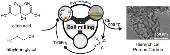
The combination of this approach with a high temperature chlorine treatment enabled us to simultaneously carbonize the polymer and selectively remove the titania. By this way, we obtained a hierarchical carbon with a high pore volume, high specific surface area, tunable mesopore volume, and a well-defined pore-size distribution. The material was further investigated as supercapacitor electrode using organic and ionic liquid electrolytes (Figure 1).
![[1860-5397-13-130-1]](/bjoc/content/figures/1860-5397-13-130-1.png?scale=2.0&max-width=1024&background=FFFFFF)
Figure 1: Synthesis of hierarchical porous carbons by mechanochemical polymerization of ethylene glycol (EG) with citric acid (CA) and Ti(IV) isopropoxide as a porogen, resulting in CA-EG polymers. After carbochlorination at 900 °C hierarchical carbons are obtained. The byproduct TiCl4 can be recycled to be used as Ti(IV) isopropoxide, and acts as porogen in further syntheses.
Figure 1: Synthesis of hierarchical porous carbons by mechanochemical polymerization of ethylene glycol (EG) ...
Results and Discussion
Mechanochemical synthesis of the polymeric precursor
For a typical synthesis, ethylene glycol (EG), citric acid (CA), and titanium isopropoxide (TIPP) were ground with a molar ratio of 3:1:1 in a ZrO2 milling cup for 5 min. A practical indicator for a successful mechanochemical reaction is a color change. The white and colorless educts turn to a yellow polymer with a honey-like texture. We first characterized the polymerization of the educts induced by mechanochemical forces by IR spectroscopy (Figure 2). Two bands at 1703 cm−1 and 1136 cm−1 appear, indicating the formation of the polyester (EG-CA). Likewise, the characteristic bands of the educts (CA: 1210 cm−1; EG: 1418 cm−1) become less pronounced and much broader as they are gradually consumed by the mechanically-induced polymerization. The spectrum of the Ti-containing polymer (Polymer-SF-3) displays the appearance of a band at 1558 cm−1, which corresponds to titanium, bidentate to a carboxylic group [50]. Additionally, the blue-shift of the vibration at 1703 cm−1 indicates complexation [51]. The sample Polymer-SF-3 was investigated by matrix-assisted laser desorption/ionization with a time-of-flight mass spectrometer (MALDI–TOF) revealing a weight-averaged molar mass (Mw) of 2015.6 g mol−1, which is equivalent to 6 monomeric units.
![[1860-5397-13-130-2]](/bjoc/content/figures/1860-5397-13-130-2.png?scale=2.0&max-width=1024&background=FFFFFF)
Figure 2: Infrared spectra of the monomers ethylene glycol (EG, blue) and citric acid (CA, green blue), the metal-free polymer achieved by 5 min ball milling with ZrO2 balls (d = 15 mm) (EG-CA, dark blue) and the polymeric precursor after adding titanium(IV) isopropoxide (Polymer-SF-3, orange).
Figure 2: Infrared spectra of the monomers ethylene glycol (EG, blue) and citric acid (CA, green blue), the m...
Synthesis of the hierarchical porous carbons
After the mechanochemical synthesis, we conducted a carbochlorination reaction, leading to the carbonization of the precursor and the removal of the dispersed titanium species (Equation 1). This process is comparable to the industrial Kroll process and responsible for the generation of mesopores that correspond to the size of the former titania nanostructures [25]. While titanium is removed as gaseous TiCl4, oxygen is extracted as CO, whereby carbon is being partially consumed as well. This partial carbon removal leads to an etching of the carbon framework and an in situ formation of micropores, surrounding the formed mesopores. Consequently, a hierarchical porous carbon material is formed [52]. The resulting byproduct TiCl4 is a valuable precursor for Ti-containing [53] chemicals like Ti(IV) isopropoxide, other Ti-alkoxides, or can directly be applied in the presented synthesis approach once again [52].
![[1860-5397-13-130-i1]](/bjoc/content/inline/1860-5397-13-130-i1.svg?max-width=590&scale=1.18182)
Scanning and transmission electron micrographs indicate that the carbon material exhibits spherically shaped mesopores (Figure 3), corresponding to the removal of TiO2 particles which have been formed during the pyrolysis (Figure 4). The pores are homogenously distributed, resulting in a well-connected pore system of the carbon material (Figure 3A,B).
![[1860-5397-13-130-3]](/bjoc/content/figures/1860-5397-13-130-3.png?scale=2.0&max-width=1024&background=FFFFFF)
Figure 3: SEM (A) and TEM (B) images of the Carb-SF-3 sample.
Figure 3: SEM (A) and TEM (B) images of the Carb-SF-3 sample.
To display the complete removal of the porogenous TiO2, we compared the XRD pattern (Figure 4) of the material at different synthesis steps: after mechanochemical polymerization (Polymer-SF-3), after temperature treatment but before Cl2 addition (Comp-SF-3), and after the carbochlorination reaction (Carb-SF-3).
![[1860-5397-13-130-4]](/bjoc/content/figures/1860-5397-13-130-4.png?scale=2.0&max-width=1024&background=FFFFFF)
Figure 4: XRD-pattern of the polymeric precursor (Polymer-SF-3, orange), the carbonized composite (Comp-SF-3, black) and the carbon received by chlorine treatment (Carb-SF-3, red).
Figure 4: XRD-pattern of the polymeric precursor (Polymer-SF-3, orange), the carbonized composite (Comp-SF-3,...
The absence of X-ray reflections confirms the amorphous nature of the polymeric precursor. Titanium is atomically coordinated and distributed within the polymer and does not form crystalline TiO2 nanoparticle domains. After carbonization broadened reflections occur due to the conversion of the bidenated Ti atoms to TiO2 nanoparticles of the rutile and anatase modification. We calculated the average domain size of crystalline TiO2 from the reflections at 25.4°, 48.0°, and 54.5° 2θ to be 6–9 nm after background adjustment using the Scherrer equation. Carbochlorination will remove these nanoparticles, leading to mesopores of comparable size. The XRD pattern of the carbon shows the broad (002) reflection of nanocrystalline carbon, but all signals related to titania have disappeared. This assumption was further supported by EDX measurements (Table 1), showing a Ti content below the detection limit.
Table 1: Porosity and composition data summary for the different samples.
| Samplesa |
SSABETb
/ m2 g−1 |
SSADFT,microc
/ m2 g−1 |
Vtotald
/ cm3 g−1 |
Vmesoe
/ cm3 g−1 |
Vmicrof
/ cm3 g−1 |
dmesoporeg
/ nm |
Ti contenth
/ % |
|---|---|---|---|---|---|---|---|
| Polymer-SF-3i | – | – | – | – | – | – | 15.7j |
| Comp-SF-3 | 298 | 185 | 0.17 | 0.10 | 0.07 | – | 45.8 ± 13.4 |
| Carb-SF-1 | 1442 | 623 | 1.34 | 1.11 | 0.23 | 4–14 | <d.l. |
| Carb-SF-2 | 1532 | 480 | 1.62 | 1.43 | 0.19 | 4; 6–12 | <d.l. |
| Carb-SF-3 | 1814 | 558 | 1.83 | 1.62 | 0.23 | 4; 6–14 | <d.l. |
| CarbHF-SF-3 | 291 | 144 | 0.20 | 0.14 | 0.06 | – | n.d. |
| Comp-LA-3 | 312 | 173 | 0.18 | 0.14 | 0.04 | – | 62.8 ± 16.7 |
| Carb-LA-3 | 1590 | 445 | 1.59 | 1.41 | 0.18 | 4; 6–13 | <d.l. |
| CarbHF-LA-3 | 706 | 123 | 0.62 | 0.48 | 0.14 | 4–12 | 11.1 |
aSample code x−y−z as follows, x describes the material after polymerization (Polymer), after heat treatment (Comp) and after carbochlorination (Carbon), the indices HF notices that the template was removed by HF instead of Cl2, y describes the reaction conducted solvent-free (SF) or liquid-assisted (LA), z describes the ratio of EG to CA. bSpecific surface area (SSA) determined in a pressure range of 0.05 < p/p0 < 0.2. cSpecific surface area of the mesopores determined by QSDFT below 2 nm. dTotal pore volume determined at p/p0 = 0.99. eMesopore volume = Vtotal – Vmicro. fMicropore volume determined by QSDFT below 2 nm. gMesopore size determined by QSDFT kernel for slit-shaped, cylindrical, spherical pores using the adsorption branch. hTi content determined by EDX measurement, <d.l. = below detection limit. iThe polymer is non-porous. jThe polymer is not stable in the electron beam; therefore, the composition must be determined from thermogravimetric analysis (TG) rather than from EDX.
The pore structure of the materials was analyzed by nitrogen physisorption (Figure 5A). Neither the polymer (Polymer-SF-3) nor the carbonized composite material (Comp-SF-3) show a significant porosity (Table 1). This was expected since the porogens have not been removed during this step in the synthesis. The low specific surface area of 298 m2 g−1 for the composite arises from chemical activation processes of volatile functional groups such as carboxylic acids, which form micropores during pyrolysis.
![[1860-5397-13-130-5]](/bjoc/content/figures/1860-5397-13-130-5.png?scale=2.0&max-width=1024&background=FFFFFF)
Figure 5: Nitrogen physisorption isotherms for carbon samples achieved from (A) different amounts of ethylene glycol and (B) different syntheses.
Figure 5: Nitrogen physisorption isotherms for carbon samples achieved from (A) different amounts of ethylene...
After carbochlorination at 900 °C, the obtained carbon (Carb-SF-3) shows a well-developed micro- and mesoporosity, obvious due to a type IV isotherm and a high nitrogen uptake at low relative pressure, which is attributed to the amount of micropores in the samples. The obtained material has a high specific surface area of up to 1814 m2 g−1 and a pore volume of 1.83 cm3 g−1. The contributions of the individual pore-size increments are shown in Table 1 and Figure 6. The carbons possess narrowly distributed micropores with an average size of 0.96 nm (due to the in situ activation process), as well as mesopores with an average diameter of 8 nm (due to the removal of TiO2 nanodomains) (Figure 6, Equation 1). The mesopore diameter (Table 1 and Figure 6) aligns very well with the calculated domain size of TiO2 nanocrystals derived from the Scherrer equation. A more precisely evaluation of the hierarchical pore structure is given in Table S1 in Supporting Information File 1.
![[1860-5397-13-130-6]](/bjoc/content/figures/1860-5397-13-130-6.png?scale=2.0&max-width=1024&background=FFFFFF)
Figure 6: Volume histogram of the different samples calculated using a QSDFT-kernel for slit, cylindrical and spherical pores on the adsorption branch.
Figure 6: Volume histogram of the different samples calculated using a QSDFT-kernel for slit, cylindrical and...
We further investigated the influence of the EG to CA ratio on the porosity of the material, while keeping the TIPP to CA ratio constant (1:1). The pore volume increased with a higher content of ethylene glycol from 1.34 cm3 g−1 for a ratio of 1:1 to 1.83 cm3 g−1 for a ratio of 3:1. This is mainly attributed to the increased mesopore volume, while the micropore volume stayed nearly the same (0.20 cm3 g−1, Table 1). The higher mesopore content originates from the higher amount of ethylene glycol, which promotes the formation of more slightly larger pores. This process finally leads to a higher mesopore volume at the expense of a narrower pore-size distribution (Figure 6). The EG ratio does not impact the particle size of the TiO2 nanostructures and thus the pore-size distributions are similar for all investigated materials (average diameter of 8 nm). The reaction in total absence of EG yields white powder next to purely black carbon phases (see Figure S2, Supporting Information File 1). This indicates that the carbon content was insufficient and demonstrates the inevitable role of EG.
To further investigate the mechanochemical polymerization and the carbochlorination step, we conducted the synthesis under liquid-assisted conditions while adding ethanol as a solvent to see if there is a difference in the polymerization and investigated an alternative template removal approach based on etching with hydrofluoric acid (HF) as well [54]. The latter is a common process used in industry [55]. However, by doing so, it is impossible to remove the porogenous TiO2 completely from the carbon matrix (sample CarbHF-SF-3). The resulting material still contained 11.1 wt % of Ti and did not show a high porosity (Figure 5B and Table 1) with a pore volume of 0.20 cm3 g−1 and a surface area of 291 m2 g−1. Indeed, the high temperature chlorination reaction is essential to obtain the full porosity of the desired carbon. However, when we conducted the mechanochemical polymerization in the presence of small amounts of ethanol (liquid-assisted grinding, LA), the porogens could be partially removed by HF (CarbHF-LA-3). We assume that the carbon matrix obtained from a solvent-free approach is possibly denser and thus the diffusion of HF to the particles is inhibited (incomplete removal). This aligns with the assumption that the energy-input and accordingly the embedding of the particles are higher in case of solvent-free syntheses. When we compare SF and LA samples (both received by carbochlorination), we observe full template removal and obtain hierarchical porous carbons with high surface area and pore volume (Table 1 and Figure 5B). The addition of a solvent during the mechanochemical synthesis does not influence the porosity of the composite materials, since both composites (Comp-SF-3 and Comp-LA-3) provide the same pore volume (0.2 cm3 g−1) and SSA (300 m2 g−1, Table 1). However, the carbons derived after carbochlorination differ in their porosities. The solvent-free synthesis results in a higher specific surface area and pore volume as compared to the liquid-assisted approach. We suggest that this is also attributed to more homogenously distributed particles while conducting the polymerization solvent-free. In the presence of solvents, a phase-separation phenomena might be induced, which results in a lower pore volume of the received carbon material (Table 1). Although chlorine gas is widely used in many industrial processes such as the Kroll process, it should be the attempt of future research to substitute chlorine gas by a green alternative to advance this mechanochemical process to an even more sustainable synthesis.
Application as supercapacitor electrodes
We selected Carb-SF-3 as electrode material in a symmetrical supercapacitor because of its high specific surface area and pore volume (Table 1). The electrochemical characterization was done in 1 M TEA-BF4 in acetonitrile (ACN) and neat EMIM-BF4 as an ionic liquid. Since ionic liquids show a lower ion mobility as compared to aqueous or organic electrolytes, a well-connected transport pore system is of particular importance to guarantee a fast ion transport and should result in better power performance [21,56]. Hierarchical pore systems provide enhanced ion transport in meso-/macropores in combination with high energy density due to accessible surface area in micropores [21].
The energy storage is accomplished by ion electrosorption as can be inferred from the rectangular shaped cyclic voltammograms (CVs) in both electrolytes (Figure 7A,B) [53]. At low current rates, the material shows good specific capacitance (Table 2) of 138 F g−1 in neat EMIM-BF4 and 98 F g−1 in 1 M TEA-BF4 (ACN) determined by galvanostatic cycling with potential limitation at 0.1 A g−1. These values are comparable to other known Kroll carbons [52] and non-doped mesoporous carbons [57].
![[1860-5397-13-130-7]](/bjoc/content/figures/1860-5397-13-130-7.png?scale=2.0&max-width=1024&background=FFFFFF)
Figure 7: Cyclic voltammograms performed with different scan rates in (A) 1 M TEA-BF4 (ACN) and (B) EMIM-BF4; galvanostatic charge/discharge curves in two different electrolytes at different specific currents (C); normalized rate capability test with different specific currents (D) in comparison to another Kroll carbon (from [52]) and a mesoporous template carbon (from [57]) with comparable mesopore sizes and surface areas.
Figure 7: Cyclic voltammograms performed with different scan rates in (A) 1 M TEA-BF4 (ACN) and (B) EMIM-BF4;...
Table 2: Electrochemical data summary for sample Carb-SF-3 measured in two different electrolytes.
aElectrolyte is abbreviated as followed: O = 1 M TEA-BF4, IL = EMIM-BF4. bWeigth normalized capacitance at 0.1 A g−1. cBET-surface area normalized capacitance at 0.1 A g−1, dSpecific energy obtained from discharge at 1 A g−1 measured in 1 M TEA-BF4 (ACN) and at 1 A g−1 in EMIM-BF4. eEnergy efficiency calculated as quotient of the specific energy obtained from discharge and charge at 1 A g−1 loss of specific capacitance, calculated as 1 − quotient of Cspec at 1 A g−1 and C0. fLoss of specific capacitance, calculated as 1 − quotient of Cspec at 10 A g−1 and C0. gReference Kroll carbon. hReference mesoporous carbon. iLoss of specific capacitance, calculated as 1 − quotient of Cspec at 1 A g−1 and C0 reference non-doped mesoporous carbon.
At a high sweep rate of 500 mV s−1, the shape of the CV, recorded in the organic electrolyte (Figure 7A) remains nearly rectangular, which indicated a high power handling ability. The ion mobility of ionic liquids is lower compared to organic electrolytes, as can be seen from the stronger deformation of the CV at high scan rates (Figure 7B). The different rate handling is also quantified by galvanostatic cycling with potential limitation (GCPL) conducted at different specific currents as presented in Figure 7C. At a high current rate of 10 A g−1, the specific capacitance was 87% in the organic electrolyte and 81% in EMIM-BF4 compared to the specific capacitance at 0.1 A g−1. The ability of the carbon to enable a fast charge and discharge is superior compared to other mesoporous non-doped carbon electrodes (Figure 7D). The material also exhibited excellent performance stability, as seen from 92% and 95% after 100 h of floating at 2.7 V for TEA-BF4 in ACN and 3.2 V in EMIM-BF4, respectively.
Conclusion
Our work presents a novel, solvent-free approach to receive hierarchical porous carbons with tailorable mesopore volume involving two synthesis steps: firstly, the mechanochemical synthesis of a polymeric composite, received by ball-milling within five minutes only, and secondly, the conversion of this precursor to a hierarchical carbon by a carbochlorination reaction. The received carbons exhibit specific surface areas of up to 1800 m2 g−1 and high mesopore volumes up to 1.8 cm3 g−1, making them very attractive for energy applications. When benchmarked as supercapacitor electrode material, Carb-SF-3 shows good specific capacitances with 98 F g−1 in 1 M TEA-BF4 (ACN) and 138 F g−1 in EMIM-BF4. Even with high specific currents of 10 A g−1 the carbon shows 87% in organic and 91% in ionic liquid electrolyte of its specific capacitance. Moreover, the carbon enables a stable electrochemical performance in both surveyed electrolytes with over 92% capacitance retention after 100 h of voltage floating. Due to the ability to design the mesopore volumes and their relatively narrow pore size distribution, the carbons are also interesting as model carbons for the investigation of different adsorption phenomena.
Experimental
Synthesis
Citric acid monohydrate (CA, purity: 95.5%) and titanium isopropoxide (TIPP, purity: 97%) were purchased from Sigma-Aldrich. Ethylene glycol (EG, purity 99.5%) was purchased from Fluka Analytics.
For the solvent-free synthesis of hierarchical porous carbons, 5.25 g CA were ground with 7.10 g TIPP in a molar ratio of 1:1 in a 45 mL ZrO2 milling cup for 1 min with 700 rpm. Seven grinding balls out of ZrO2 with a diameter of 15 mm were used. Afterwards, different amounts of EG are added and the mixture was ball-milled for another 5 min with 700 rpm. The molar ratio of CA and EG was varied from 1:3 to 1:1. For the liquid-assisted synthesis, 5 mL EtOH were added to the first grinding step.
The resulting polymer was heated to 900 °C at a heating rate of 300 °C h−1 in a horizontal tubular furnace under argon atmosphere with a flowrate of 150 mL min−1. After 1 h at 900 °C, the gas atmosphere was changed to a mixture of argon (flowrate: 70 mL min−1) and chlorine gas (flowrate: 80 mL min−1) while the temperature was held for additional 2 h at 900 °C. After cooling to 600 °C under argon, remaining chlorine was removed by hydrogen treatment (flowrate: 80 mL min−1) for 1 h.
Characterization
Nitrogen physisorption experiments were carried out with an AUTOSORB-iQ-C-XR from Quantachrome at −196 °C. Prior to the measurements, the samples were degassed for at least 24 h at 150 °C under vacuum. The specific surface area was calculated in a relative pressure range of 0.05–0.2 per the Brunauer–Emmett–Teller (BET) theory. Values for the total pore volume were determined at a relative pressure of 0.99. Pore size distributions were achieved by applying the hybrid QSDFT model for slit-shaped, cylindrical and spherical pores at −196 °C. The micropore volume was calculated from the cumulative QSDFT pore volume data at 2 nm. Energy dispersive X-ray (EDX) analyses were performed with a SU8020 from Hitachi at an acceleration voltage of 20 kV. Transmission electron microscopy (TEM) was executed with a TEM Libra 200 system from Carl Zeiss Microscopy GmbH with an acceleration voltage of 200 kV. For the TEM, the sample powder was sonicated in acetone for 5 s. A lacey-carbon film on copper net (300 mesh) from Plano was used as TEM grid. Afterward, 5 µL were dropped on the grid and evaporated. IR spectra were conducted with the use of ATR technique, as well as with the DRIFTS technique with a Bruker Vertex 70 in the range of 4000–400 cm−1. The hierarchical porous carbon was prepared as free standing electrodes. The carbon material was dispersed in ethanol and we added 10 wt % polytetrafluoroethylene (PTFE, 60 wt % solution in water) as the polymer binder. By crushing the mixture in an agate mortar until the ethanol is evaporated, a dough-like mass was obtained, which was further rolled out until the electrode had a thickness of about 150 µm. The electrode was dried in a vacuum oven at 120 °C for 24 h and we used a disc cutter to obtain electrodes with a diameter of 12 mm. The measurement was done in custom-built cells in a symmetrical two-electrode setup with a quasi-reference electrode out of YP-50F bound with PTFE [58,59]. A 13 mm diameter Whatmann GF/D was used as a separator and 12 mm diameter carbon-coated aluminum discs from MTI Corporation was used as a current collector.
The electrochemical measurements were performed with a Biologic VMP-300 potentiostat/galvanostat. The specific capacitances were calculated with Equation 2 from galvanostatic cycling with potential limitation (GCPL). To compare the electrodes with other materials, they were normalized to their active mass, which is equivalent to the carbon mass in the electrodes, as well as to their specific surface area obtained by the BET method. For the graphical representation of the cyclic voltammograms, the specific capacitances were calculated with Equation 3.
![[1860-5397-13-130-i2]](/bjoc/content/inline/1860-5397-13-130-i2.svg?max-width=590&scale=1.18182)
![[1860-5397-13-130-i3]](/bjoc/content/inline/1860-5397-13-130-i3.svg?max-width=590&scale=1.18182)
For the calculation of the specific energy of the carbon electrodes in two different electrolytes, Equation 4 was applied with discharge data after the iR drop.
![[1860-5397-13-130-i4]](/bjoc/content/inline/1860-5397-13-130-i4.svg?max-width=590&scale=1.18182)
Supporting Information
| Supporting Information File 1: Additional data. | ||
| Format: PDF | Size: 364.3 KB | Download |
Acknowledgements
DL and LB gratefully acknowledge the Federal Ministry of Education and Research (Bundesministerium für Bildung und Forschung, BMBF) for support of the Mechanocarb project (award number 03SF0498). DL wants to thank Kristian Schneider for the TEM measurement and the Leibniz-Institut für Polymerforschung Dresden e.V. for access to the TEM as well as Sebastian Ehrling for the SEM/EDX measurements. NJ and VP thank Prof. Eduard Arzt (INM) for his continuing support and Aura Tolosa (INM) for discussions.
References
-
Rodríguez-reinoso, F. Carbon 1998, 36, 159–175. doi:10.1016/S0008-6223(97)00173-5
Return to citation in text: [1] -
Suda, H.; Haraya, K. Chem. Commun. 1997, 93–94. doi:10.1039/a606385c
Return to citation in text: [1] -
Suda, H.; Haraya, K. J. Phys. Chem. B 1997, 101, 3988–3994. doi:10.1021/jp963997u
Return to citation in text: [1] -
Rose, M.; Korenblit, Y.; Kockrick, E.; Borchardt, L.; Oschatz, M.; Kaskel, S.; Yushin, G. Small 2011, 7, 1108–1117. doi:10.1002/smll.201001898
Return to citation in text: [1] [2] -
Simon, P.; Taberna, P.-L.; Béguin, F. Electrical Double-Layer Capacitors and Carbons for EDLCs. In Supercapacitors: Materials, Systems, and Applications; Béguin, F.; Frackowiak, E., Eds.; Wiley-VCH: Weinheim, 2013; pp 131–165.
Return to citation in text: [1] -
Oschatz, M.; Boukhalfa, S.; Nickel, W.; Hofmann, J. P.; Fischer, C.; Yushin, G.; Kaskel, S. Carbon 2017, 113, 283–291. doi:10.1016/j.carbon.2016.11.050
Return to citation in text: [1] -
Titirici, M.-M.; White, R. J.; Brun, N.; Budarin, V. L.; Su, D. S.; del Monte, F.; Clark, J. H.; MacLachlan, M. J. Chem. Soc. Rev. 2015, 44, 250–290. doi:10.1039/C4CS00232F
Return to citation in text: [1] [2] -
Simon, P.; Gogotsi, Y. Nat. Mater. 2008, 7, 845–854. doi:10.1038/nmat2297
Return to citation in text: [1] -
Merlet, C.; Rotenberg, B.; Madden, P. A.; Taberna, P.-L.; Simon, P.; Gogotsi, Y.; Salanne, M. Nat. Mater. 2012, 11, 306–310. doi:10.1038/nmat3260
Return to citation in text: [1] -
Piwek, J.; Platek, A.; Fic, K.; Frackowiak, E. Electrochim. Acta 2016, 215, 179–186. doi:10.1016/j.electacta.2016.08.061
Return to citation in text: [1] -
Borchardt, L.; Oschatz, M.; Kaskel, S. Mater. Horiz. 2014, 1, 157–168. doi:10.1039/C3MH00112A
Return to citation in text: [1] -
Hippauf, F.; Lunow, D.; Huettner, C.; Nickel, W.; Borchardt, L.; Henle, T.; Kaskel, S. Carbon 2015, 87, 309–316. doi:10.1016/j.carbon.2015.02.023
Return to citation in text: [1] -
Kyotani, T. Carbon 2000, 38, 269–286. doi:10.1016/S0008-6223(99)00142-6
Return to citation in text: [1] -
Jäckel, N.; Simon, P.; Gogotsi, Y.; Presser, V. ACS Energy Lett. 2016, 1, 1262–1265. doi:10.1021/acsenergylett.6b00516
Return to citation in text: [1] -
Borchardt, L.; Nickel, W.; Casco, M.; Senkovska, I.; Bon, V.; Wallacher, D.; Grimm, N.; Krause, S.; Silvestre-Albero, J. Phys. Chem. Chem. Phys. 2016, 18, 20607–20614. doi:10.1039/C6CP03993F
Return to citation in text: [1] -
Oschatz, M.; Hoffmann, H. C.; Pallmann, J.; Schaber, J.; Borchardt, L.; Nickel, W.; Senkovska, I.; Rico-Francés, S.; Silvestre-Albero, J.; Kaskel, S.; Brunner, E. Chem. Mater. 2014, 26, 3280–3288. doi:10.1021/cm501102y
Return to citation in text: [1] -
Oschatz, M.; Borchardt, L.; Hippauf, F.; Nickel, W.; Kaskel, S.; Brunner, E. Annu. Rep. NMR Spectrosc. 2016, 87, 237–318. doi:10.1016/bs.arnmr.2015.08.003
Return to citation in text: [1] -
Péan, C.; Merlet, C.; Rotenberg, B.; Madden, P. A.; Taberna, P.-L.; Daffos, B.; Salanne, M.; Simon, P. ACS Nano 2014, 8, 1576–1583. doi:10.1021/nn4058243
Return to citation in text: [1] -
Oschatz, M.; Kockrick, E.; Rose, M.; Borchardt, L.; Klein, N.; Senkovska, I.; Freudenberg, T.; Korenblit, Y.; Yushin, G.; Kaskel, S. Carbon 2010, 48, 3987–3992. doi:10.1016/j.carbon.2010.06.058
Return to citation in text: [1] -
Fuertes, A. B.; Pico, F.; Rojo, J. M. J. Power Sources 2004, 133, 329–336. doi:10.1016/j.jpowsour.2004.02.013
Return to citation in text: [1] -
Wang, D.-W.; Li, F.; Liu, M.; Lu, G. Q.; Cheng, H.-M. Angew. Chem., Int. Ed. 2007, 47, 373–376. doi:10.1002/anie.200702721
Return to citation in text: [1] [2] [3] -
Meng, Y.; Gu, D.; Zhang, F.; Shi, Y.; Yang, H.; Li, Z.; Yu, C.; Tu, B.; Zhao, D. Angew. Chem., Int. Ed. 2005, 44, 7053–7059. doi:10.1002/anie.200501561
Return to citation in text: [1] -
Ryoo, R.; Joo, S. H.; Jun, S. J. Phys. Chem. B 1999, 103, 7743–7746. doi:10.1021/jp991673a
Return to citation in text: [1] -
Wang, Y.; Wang, F.; Chen, Y.; Li, B.; Zhang, C.; Cui, L.; Kang, S.; Li, X. Int. J. Electrochem. Sci. 2013, 8, 7868–7874.
Return to citation in text: [1] -
Oschatz, M.; Thieme, S.; Borchardt, L.; Lohe, M. R.; Biemelt, T.; Brückner, J.; Althues, H.; Kaskel, S. Chem. Commun. 2013, 49, 5832–5834. doi:10.1039/c3cc42841a
Return to citation in text: [1] [2] -
Fechler, N.; Fellinger, T.-P.; Antonietti, M. Adv. Mater. 2013, 25, 75–79. doi:10.1002/adma.201203422
Return to citation in text: [1] -
Yang, C.-M.; Weidenthaler, C.; Spliethoff, B.; Mayanna, M.; Schüth, F. Chem. Mater. 2005, 10, 355–358. doi:10.1021/cm049164v
Return to citation in text: [1] -
Zhu, H.; Liu, Z.; Wang, Y.; Kong, D.; Yuan, X.; Xie, Z. Chem. Mater. 2008, 20, 1134–1139. doi:10.1021/cm071385o
Return to citation in text: [1] -
Chuenchom, L.; Kraehnert, R.; Smarsly, B. M. Soft Matter 2012, 8, 10801–10812. doi:10.1039/c2sm07448f
Return to citation in text: [1] -
Sakintuna, B.; Yürüm, Y. Ind. Eng. Chem. Res. 2005, 44, 2893–2902. doi:10.1021/ie049080w
Return to citation in text: [1] -
Gawande, M. B.; Bonifácio, V. D. B.; Luque, R.; Branco, P. S.; Varma, R. S. ChemSusChem 2014, 7, 24–44. doi:10.1002/cssc.201300485
Return to citation in text: [1] -
Tojo, T.; Zhang, Q.; Saito, F. J. Solid State Chem. 2006, 179, 433–437. doi:10.1016/j.jssc.2005.11.002
Return to citation in text: [1] [2] -
Stolle, A.; Szuppa, T.; Leonhardt, S. E. S.; Ondruschka, B. Chem. Soc. Rev. 2011, 40, 2317–2329. doi:10.1039/c0cs00195c
Return to citation in text: [1] -
James, S. L.; Adams, C. J.; Bolm, C.; Braga, D.; Collier, P.; Friščić, T.; Grepioni, F.; Harris, K. D. M.; Hyett, G.; Jones, W.; Krebs, A.; Mack, J.; Maini, L.; Orpen, A. G.; Parkin, I. P.; Shearouse, W. C.; Steed, J. W.; Waddell, D. C. Chem. Soc. Rev. 2012, 41, 413–447. doi:10.1039/C1CS15171A
Return to citation in text: [1] -
Jörres, M.; Aceña, J. L.; Soloshonok, V. A.; Bolm, C. ChemCatChem 2015, 7, 1265–1269. doi:10.1002/cctc.201500102
Return to citation in text: [1] -
Wang, Y.-F.; Chen, R.-X.; Wang, K.; Zhang, B.-B.; Li, Z.-B.; Xu, D.-Q. Green Chem. 2012, 14, 893–895. doi:10.1039/c2gc16521j
Return to citation in text: [1] -
Grätz, S.; Borchardt, L. RSC Adv. 2016, 6, 64799–64802. doi:10.1039/C6RA15677K
Return to citation in text: [1] -
Schneidermann, C.; Jäckel, N.; Oswald, S.; Giebeler, L.; Presser, V.; Borchardt, L. ChemSusChem 2017, 10, 2416–2424. doi:10.1002/cssc.201700459
Return to citation in text: [1] -
Wang, G.-W.; Komatsu, K.; Murata, Y.; Shiro, M. Nature 1997, 387, 583–586. doi:10.1038/42439
Return to citation in text: [1] -
Kabbani, M. A.; Tiwary, C. S.; Autreto, P. A. S.; Brunetto, G.; Som, A.; Krishnadas, K. R.; Ozden, S.; Hackenberg, K. P.; Gong, Y.; Galvao, D. S.; Vajtai, R.; Kabbani, A. T.; Pradeep, T.; Ajayan, P. M. Nat. Commun. 2015, 6, No. 7291. doi:10.1038/ncomms8291
Return to citation in text: [1] -
Kunitake, M.; Uemura, S.; Ito, O.; Fujiwara, K.; Murata, Y.; Komatsu, K. Angew. Chem., Int. Ed. 2002, 41, 969–972. doi:10.1002/1521-3773(20020315)41:6<969::AID-ANIE969>3.0.CO;2-I
Return to citation in text: [1] -
Troschke, E.; Grätz, S.; Lübken, T.; Borchardt, L. Angew. Chem., Int. Ed. 2017, 56, 6859–6863. doi:10.1002/anie.201702303
Return to citation in text: [1] -
Grätz, S.; Wolfrum, B.; Borchardt, L. Green Chem. 2017, in press. doi:10.1039/C7GC00693D
Return to citation in text: [1] -
Ribeiro, P. C.; de Melo da Costa, A. C. F.; Kiminami, R. H. G. A.; Sasaki, J. M.; Lira, H. L. Mater. Res. (Sao Carlos, Braz.) 2013, 16, 468–472. doi:10.1590/S1516-14392012005000176
Return to citation in text: [1] -
Pechini, M. P. Method of Preparing Lead and Alkaline Earth Titanates and Niobates and Coating Method Using the Same To Form a Capacitor. U.S. Patent US3330697 A, July 11, 1967.
Return to citation in text: [1] -
Strubel, P.; Althues, H.; Kaskel, S. Carbon 2016, 107, 705–710. doi:10.1016/j.carbon.2016.06.075
Return to citation in text: [1] -
Sevilla, M.; Fuertes, A. B. ACS Nano 2014, 8, 5069–5078. doi:10.1021/nn501124h
Return to citation in text: [1] -
Ferrero, G. A.; Sevilla, M.; Fuertes, A. B. Carbon 2015, 88, 239–251. doi:10.1016/j.carbon.2015.03.014
Return to citation in text: [1] -
Tao, X.; Chen, X.; Xia, Y.; Huang, H.; Gan, Y.; Wu, R.; Chen, F.; Zhang, W. J. Mater. Chem. A 2013, 1, 3295–3303. doi:10.1039/c2ta01213h
Return to citation in text: [1] -
Vasconcelos, D. C. L.; Costa, V. C.; Nunes, E. H. M.; Sabioni, A. C. S.; Gasparon, M.; Vasconcelos, W. L. Mater. Sci. Appl. 2011, 2, 1375–1382. doi:10.4236/msa.2011.210186
Return to citation in text: [1] -
Hočevar, M.; Berginc, M.; Topič, M.; Krašovec, U. O. J. Sol-Gel Sci. Technol. 2010, 53, 647–654. doi:10.1007/s10971-009-2144-6
Return to citation in text: [1] -
Oschatz, M.; Boukhalfa, S.; Nickel, W.; Lee, J. T.; Klosz, S.; Borchardt, L.; Eychmüller, A.; Yushin, G.; Kaskel, S. J. Mater. Chem. A 2014, 2, 5131–5139. doi:10.1039/c3ta14815g
Return to citation in text: [1] [2] [3] [4] [5] -
Nelles, J. Preparation of Titanium Alcoholates and Phenolates. U.S. Patent US2187821 A, Jan 23, 1940.
Return to citation in text: [1] [2] -
Hernández, J. G.; Friščić, T. Tetrahedron Lett. 2015, 56, 4253–4265. doi:10.1016/j.tetlet.2015.03.135
Return to citation in text: [1] -
Kim, K.; Choi, M.; Ryoo, R. Carbon 2013, 60, 175–185. doi:10.1016/j.carbon.2013.04.011
Return to citation in text: [1] -
Frackowiak, E. Phys. Chem. Chem. Phys. 2007, 9, 1774–1785. doi:10.1039/b618139m
Return to citation in text: [1] -
Fuertes, A. B.; Lota, G.; Centeno, T. A.; Frackowiak, E. Electrochim. Acta 2005, 50, 2799–2805. doi:10.1016/j.electacta.2004.11.027
Return to citation in text: [1] [2] [3] -
Weingarth, D.; Foelske-Schmitz, A.; Wokaun, A.; Kötz, R. Electrochem. Commun. 2012, 18, 116–118. doi:10.1016/j.elecom.2012.02.040
Return to citation in text: [1] -
Ruch, P. W.; Cericola, D.; Hahn, M.; Kötz, R.; Wokaun, A. J. Electroanal. Chem. 2009, 636, 128–131. doi:10.1016/j.jelechem.2009.09.007
Return to citation in text: [1]
| 52. | Oschatz, M.; Boukhalfa, S.; Nickel, W.; Lee, J. T.; Klosz, S.; Borchardt, L.; Eychmüller, A.; Yushin, G.; Kaskel, S. J. Mater. Chem. A 2014, 2, 5131–5139. doi:10.1039/c3ta14815g |
| 53. | Nelles, J. Preparation of Titanium Alcoholates and Phenolates. U.S. Patent US2187821 A, Jan 23, 1940. |
| 52. | Oschatz, M.; Boukhalfa, S.; Nickel, W.; Lee, J. T.; Klosz, S.; Borchardt, L.; Eychmüller, A.; Yushin, G.; Kaskel, S. J. Mater. Chem. A 2014, 2, 5131–5139. doi:10.1039/c3ta14815g |
| 1. | Rodríguez-reinoso, F. Carbon 1998, 36, 159–175. doi:10.1016/S0008-6223(97)00173-5 |
| 8. | Simon, P.; Gogotsi, Y. Nat. Mater. 2008, 7, 845–854. doi:10.1038/nmat2297 |
| 9. | Merlet, C.; Rotenberg, B.; Madden, P. A.; Taberna, P.-L.; Simon, P.; Gogotsi, Y.; Salanne, M. Nat. Mater. 2012, 11, 306–310. doi:10.1038/nmat3260 |
| 10. | Piwek, J.; Platek, A.; Fic, K.; Frackowiak, E. Electrochim. Acta 2016, 215, 179–186. doi:10.1016/j.electacta.2016.08.061 |
| 29. | Chuenchom, L.; Kraehnert, R.; Smarsly, B. M. Soft Matter 2012, 8, 10801–10812. doi:10.1039/c2sm07448f |
| 30. | Sakintuna, B.; Yürüm, Y. Ind. Eng. Chem. Res. 2005, 44, 2893–2902. doi:10.1021/ie049080w |
| 57. | Fuertes, A. B.; Lota, G.; Centeno, T. A.; Frackowiak, E. Electrochim. Acta 2005, 50, 2799–2805. doi:10.1016/j.electacta.2004.11.027 |
| 7. | Titirici, M.-M.; White, R. J.; Brun, N.; Budarin, V. L.; Su, D. S.; del Monte, F.; Clark, J. H.; MacLachlan, M. J. Chem. Soc. Rev. 2015, 44, 250–290. doi:10.1039/C4CS00232F |
| 7. | Titirici, M.-M.; White, R. J.; Brun, N.; Budarin, V. L.; Su, D. S.; del Monte, F.; Clark, J. H.; MacLachlan, M. J. Chem. Soc. Rev. 2015, 44, 250–290. doi:10.1039/C4CS00232F |
| 31. | Gawande, M. B.; Bonifácio, V. D. B.; Luque, R.; Branco, P. S.; Varma, R. S. ChemSusChem 2014, 7, 24–44. doi:10.1002/cssc.201300485 |
| 52. | Oschatz, M.; Boukhalfa, S.; Nickel, W.; Lee, J. T.; Klosz, S.; Borchardt, L.; Eychmüller, A.; Yushin, G.; Kaskel, S. J. Mater. Chem. A 2014, 2, 5131–5139. doi:10.1039/c3ta14815g |
| 4. | Rose, M.; Korenblit, Y.; Kockrick, E.; Borchardt, L.; Oschatz, M.; Kaskel, S.; Yushin, G. Small 2011, 7, 1108–1117. doi:10.1002/smll.201001898 |
| 5. | Simon, P.; Taberna, P.-L.; Béguin, F. Electrical Double-Layer Capacitors and Carbons for EDLCs. In Supercapacitors: Materials, Systems, and Applications; Béguin, F.; Frackowiak, E., Eds.; Wiley-VCH: Weinheim, 2013; pp 131–165. |
| 6. | Oschatz, M.; Boukhalfa, S.; Nickel, W.; Hofmann, J. P.; Fischer, C.; Yushin, G.; Kaskel, S. Carbon 2017, 113, 283–291. doi:10.1016/j.carbon.2016.11.050 |
| 25. | Oschatz, M.; Thieme, S.; Borchardt, L.; Lohe, M. R.; Biemelt, T.; Brückner, J.; Althues, H.; Kaskel, S. Chem. Commun. 2013, 49, 5832–5834. doi:10.1039/c3cc42841a |
| 53. | Nelles, J. Preparation of Titanium Alcoholates and Phenolates. U.S. Patent US2187821 A, Jan 23, 1940. |
| 2. | Suda, H.; Haraya, K. Chem. Commun. 1997, 93–94. doi:10.1039/a606385c |
| 3. | Suda, H.; Haraya, K. J. Phys. Chem. B 1997, 101, 3988–3994. doi:10.1021/jp963997u |
| 26. | Fechler, N.; Fellinger, T.-P.; Antonietti, M. Adv. Mater. 2013, 25, 75–79. doi:10.1002/adma.201203422 |
| 27. | Yang, C.-M.; Weidenthaler, C.; Spliethoff, B.; Mayanna, M.; Schüth, F. Chem. Mater. 2005, 10, 355–358. doi:10.1021/cm049164v |
| 28. | Zhu, H.; Liu, Z.; Wang, Y.; Kong, D.; Yuan, X.; Xie, Z. Chem. Mater. 2008, 20, 1134–1139. doi:10.1021/cm071385o |
| 52. | Oschatz, M.; Boukhalfa, S.; Nickel, W.; Lee, J. T.; Klosz, S.; Borchardt, L.; Eychmüller, A.; Yushin, G.; Kaskel, S. J. Mater. Chem. A 2014, 2, 5131–5139. doi:10.1039/c3ta14815g |
| 15. | Borchardt, L.; Nickel, W.; Casco, M.; Senkovska, I.; Bon, V.; Wallacher, D.; Grimm, N.; Krause, S.; Silvestre-Albero, J. Phys. Chem. Chem. Phys. 2016, 18, 20607–20614. doi:10.1039/C6CP03993F |
| 16. | Oschatz, M.; Hoffmann, H. C.; Pallmann, J.; Schaber, J.; Borchardt, L.; Nickel, W.; Senkovska, I.; Rico-Francés, S.; Silvestre-Albero, J.; Kaskel, S.; Brunner, E. Chem. Mater. 2014, 26, 3280–3288. doi:10.1021/cm501102y |
| 17. | Oschatz, M.; Borchardt, L.; Hippauf, F.; Nickel, W.; Kaskel, S.; Brunner, E. Annu. Rep. NMR Spectrosc. 2016, 87, 237–318. doi:10.1016/bs.arnmr.2015.08.003 |
| 20. | Fuertes, A. B.; Pico, F.; Rojo, J. M. J. Power Sources 2004, 133, 329–336. doi:10.1016/j.jpowsour.2004.02.013 |
| 21. | Wang, D.-W.; Li, F.; Liu, M.; Lu, G. Q.; Cheng, H.-M. Angew. Chem., Int. Ed. 2007, 47, 373–376. doi:10.1002/anie.200702721 |
| 21. | Wang, D.-W.; Li, F.; Liu, M.; Lu, G. Q.; Cheng, H.-M. Angew. Chem., Int. Ed. 2007, 47, 373–376. doi:10.1002/anie.200702721 |
| 56. | Frackowiak, E. Phys. Chem. Chem. Phys. 2007, 9, 1774–1785. doi:10.1039/b618139m |
| 13. | Kyotani, T. Carbon 2000, 38, 269–286. doi:10.1016/S0008-6223(99)00142-6 |
| 14. | Jäckel, N.; Simon, P.; Gogotsi, Y.; Presser, V. ACS Energy Lett. 2016, 1, 1262–1265. doi:10.1021/acsenergylett.6b00516 |
| 22. | Meng, Y.; Gu, D.; Zhang, F.; Shi, Y.; Yang, H.; Li, Z.; Yu, C.; Tu, B.; Zhao, D. Angew. Chem., Int. Ed. 2005, 44, 7053–7059. doi:10.1002/anie.200501561 |
| 23. | Ryoo, R.; Joo, S. H.; Jun, S. J. Phys. Chem. B 1999, 103, 7743–7746. doi:10.1021/jp991673a |
| 24. | Wang, Y.; Wang, F.; Chen, Y.; Li, B.; Zhang, C.; Cui, L.; Kang, S.; Li, X. Int. J. Electrochem. Sci. 2013, 8, 7868–7874. |
| 21. | Wang, D.-W.; Li, F.; Liu, M.; Lu, G. Q.; Cheng, H.-M. Angew. Chem., Int. Ed. 2007, 47, 373–376. doi:10.1002/anie.200702721 |
| 12. | Hippauf, F.; Lunow, D.; Huettner, C.; Nickel, W.; Borchardt, L.; Henle, T.; Kaskel, S. Carbon 2015, 87, 309–316. doi:10.1016/j.carbon.2015.02.023 |
| 54. | Hernández, J. G.; Friščić, T. Tetrahedron Lett. 2015, 56, 4253–4265. doi:10.1016/j.tetlet.2015.03.135 |
| 11. | Borchardt, L.; Oschatz, M.; Kaskel, S. Mater. Horiz. 2014, 1, 157–168. doi:10.1039/C3MH00112A |
| 4. | Rose, M.; Korenblit, Y.; Kockrick, E.; Borchardt, L.; Oschatz, M.; Kaskel, S.; Yushin, G. Small 2011, 7, 1108–1117. doi:10.1002/smll.201001898 |
| 18. | Péan, C.; Merlet, C.; Rotenberg, B.; Madden, P. A.; Taberna, P.-L.; Daffos, B.; Salanne, M.; Simon, P. ACS Nano 2014, 8, 1576–1583. doi:10.1021/nn4058243 |
| 19. | Oschatz, M.; Kockrick, E.; Rose, M.; Borchardt, L.; Klein, N.; Senkovska, I.; Freudenberg, T.; Korenblit, Y.; Yushin, G.; Kaskel, S. Carbon 2010, 48, 3987–3992. doi:10.1016/j.carbon.2010.06.058 |
| 55. | Kim, K.; Choi, M.; Ryoo, R. Carbon 2013, 60, 175–185. doi:10.1016/j.carbon.2013.04.011 |
| 36. | Wang, Y.-F.; Chen, R.-X.; Wang, K.; Zhang, B.-B.; Li, Z.-B.; Xu, D.-Q. Green Chem. 2012, 14, 893–895. doi:10.1039/c2gc16521j |
| 37. | Grätz, S.; Borchardt, L. RSC Adv. 2016, 6, 64799–64802. doi:10.1039/C6RA15677K |
| 32. | Tojo, T.; Zhang, Q.; Saito, F. J. Solid State Chem. 2006, 179, 433–437. doi:10.1016/j.jssc.2005.11.002 |
| 33. | Stolle, A.; Szuppa, T.; Leonhardt, S. E. S.; Ondruschka, B. Chem. Soc. Rev. 2011, 40, 2317–2329. doi:10.1039/c0cs00195c |
| 34. | James, S. L.; Adams, C. J.; Bolm, C.; Braga, D.; Collier, P.; Friščić, T.; Grepioni, F.; Harris, K. D. M.; Hyett, G.; Jones, W.; Krebs, A.; Mack, J.; Maini, L.; Orpen, A. G.; Parkin, I. P.; Shearouse, W. C.; Steed, J. W.; Waddell, D. C. Chem. Soc. Rev. 2012, 41, 413–447. doi:10.1039/C1CS15171A |
| 57. | Fuertes, A. B.; Lota, G.; Centeno, T. A.; Frackowiak, E. Electrochim. Acta 2005, 50, 2799–2805. doi:10.1016/j.electacta.2004.11.027 |
| 32. | Tojo, T.; Zhang, Q.; Saito, F. J. Solid State Chem. 2006, 179, 433–437. doi:10.1016/j.jssc.2005.11.002 |
| 35. | Jörres, M.; Aceña, J. L.; Soloshonok, V. A.; Bolm, C. ChemCatChem 2015, 7, 1265–1269. doi:10.1002/cctc.201500102 |
| 52. | Oschatz, M.; Boukhalfa, S.; Nickel, W.; Lee, J. T.; Klosz, S.; Borchardt, L.; Eychmüller, A.; Yushin, G.; Kaskel, S. J. Mater. Chem. A 2014, 2, 5131–5139. doi:10.1039/c3ta14815g |
| 57. | Fuertes, A. B.; Lota, G.; Centeno, T. A.; Frackowiak, E. Electrochim. Acta 2005, 50, 2799–2805. doi:10.1016/j.electacta.2004.11.027 |
| 51. | Hočevar, M.; Berginc, M.; Topič, M.; Krašovec, U. O. J. Sol-Gel Sci. Technol. 2010, 53, 647–654. doi:10.1007/s10971-009-2144-6 |
| 25. | Oschatz, M.; Thieme, S.; Borchardt, L.; Lohe, M. R.; Biemelt, T.; Brückner, J.; Althues, H.; Kaskel, S. Chem. Commun. 2013, 49, 5832–5834. doi:10.1039/c3cc42841a |
| 46. | Strubel, P.; Althues, H.; Kaskel, S. Carbon 2016, 107, 705–710. doi:10.1016/j.carbon.2016.06.075 |
| 47. | Sevilla, M.; Fuertes, A. B. ACS Nano 2014, 8, 5069–5078. doi:10.1021/nn501124h |
| 48. | Ferrero, G. A.; Sevilla, M.; Fuertes, A. B. Carbon 2015, 88, 239–251. doi:10.1016/j.carbon.2015.03.014 |
| 49. | Tao, X.; Chen, X.; Xia, Y.; Huang, H.; Gan, Y.; Wu, R.; Chen, F.; Zhang, W. J. Mater. Chem. A 2013, 1, 3295–3303. doi:10.1039/c2ta01213h |
| 50. | Vasconcelos, D. C. L.; Costa, V. C.; Nunes, E. H. M.; Sabioni, A. C. S.; Gasparon, M.; Vasconcelos, W. L. Mater. Sci. Appl. 2011, 2, 1375–1382. doi:10.4236/msa.2011.210186 |
| 42. | Troschke, E.; Grätz, S.; Lübken, T.; Borchardt, L. Angew. Chem., Int. Ed. 2017, 56, 6859–6863. doi:10.1002/anie.201702303 |
| 43. | Grätz, S.; Wolfrum, B.; Borchardt, L. Green Chem. 2017, in press. doi:10.1039/C7GC00693D |
| 44. | Ribeiro, P. C.; de Melo da Costa, A. C. F.; Kiminami, R. H. G. A.; Sasaki, J. M.; Lira, H. L. Mater. Res. (Sao Carlos, Braz.) 2013, 16, 468–472. doi:10.1590/S1516-14392012005000176 |
| 45. | Pechini, M. P. Method of Preparing Lead and Alkaline Earth Titanates and Niobates and Coating Method Using the Same To Form a Capacitor. U.S. Patent US3330697 A, July 11, 1967. |
| 38. | Schneidermann, C.; Jäckel, N.; Oswald, S.; Giebeler, L.; Presser, V.; Borchardt, L. ChemSusChem 2017, 10, 2416–2424. doi:10.1002/cssc.201700459 |
| 58. | Weingarth, D.; Foelske-Schmitz, A.; Wokaun, A.; Kötz, R. Electrochem. Commun. 2012, 18, 116–118. doi:10.1016/j.elecom.2012.02.040 |
| 59. | Ruch, P. W.; Cericola, D.; Hahn, M.; Kötz, R.; Wokaun, A. J. Electroanal. Chem. 2009, 636, 128–131. doi:10.1016/j.jelechem.2009.09.007 |
| 39. | Wang, G.-W.; Komatsu, K.; Murata, Y.; Shiro, M. Nature 1997, 387, 583–586. doi:10.1038/42439 |
| 40. | Kabbani, M. A.; Tiwary, C. S.; Autreto, P. A. S.; Brunetto, G.; Som, A.; Krishnadas, K. R.; Ozden, S.; Hackenberg, K. P.; Gong, Y.; Galvao, D. S.; Vajtai, R.; Kabbani, A. T.; Pradeep, T.; Ajayan, P. M. Nat. Commun. 2015, 6, No. 7291. doi:10.1038/ncomms8291 |
| 41. | Kunitake, M.; Uemura, S.; Ito, O.; Fujiwara, K.; Murata, Y.; Komatsu, K. Angew. Chem., Int. Ed. 2002, 41, 969–972. doi:10.1002/1521-3773(20020315)41:6<969::AID-ANIE969>3.0.CO;2-I |
© 2017 Leistenschneider et al.; licensee Beilstein-Institut.
This is an Open Access article under the terms of the Creative Commons Attribution License (http://creativecommons.org/licenses/by/4.0), which permits unrestricted use, distribution, and reproduction in any medium, provided the original work is properly cited.
The license is subject to the Beilstein Journal of Organic Chemistry terms and conditions: (http://www.beilstein-journals.org/bjoc)