Abstract
The design of metal–organic frameworks (MOFs) incorporating electroactive guest molecules in the pores has become a subject of great interest in order to obtain additional electrical functionalities within the framework while maintaining porosity. Understanding the charge-transfer (CT) process between the framework and the guest molecules is a crucial step towards the design of new electroactive MOFs. Herein, we present the encapsulation of fullerenes (C60) in a mesoporous tetrathiafulvalene (TTF)-based MOF. The CT process between the electron-acceptor C60 guest and the electron-donor TTF ligand is studied in detail by means of different spectroscopic techniques and density functional theory (DFT) calculations. Importantly, gas sorption measurements demonstrate that sorption capacity is maintained after encapsulation of fullerenes, whereas the electrical conductivity is increased by two orders of magnitude due to the CT interactions between C60 and the TTF-based framework.
Introduction
Metal–organic frameworks (MOFs), which are crystalline porous materials constructed from metallic nodes and organic linkers, have been a major breakthrough in chemistry in the last decades [1,2]. Because of their immense structural and functional possibilities, this class of hybrid materials finds several applications in, for example, gas storage and separation, sensing or catalysis [3-5]. In addition, electroactive MOFs combining porosity and electrical conductivity [6-8] have also attracted much attention during the last years in view of their potential application, for example as chemiresistive sensors [9], field-effect transistors [10] or supercapacitors [11]. Whereas most MOFs are electrical insulators, some have shown to exhibit excellent electrical conductivity and high charge mobility. This was achieved either by an appropriate choice of the building units to form electronically delocalised frameworks, or by incorporating electroactive guest molecules in the pores [6,12-14]. In this direction, the incorporation of redox-active moieties [15-18] as well as the understanding of charge-transfer (CT) processes in MOFs [19-24], are excellent pathways for the rational design of new electroactive frameworks exhibiting electrical conductivity and porosity at the same time.
Fullerenes (C60) [25] have found numerous applications in different fields, ranging from molecular electronics and nanotechnology to biomedical applications, due to their exceptional electrochemical and photophysical properties [26,27]. In particular, understanding the CT processes between the electron-acceptor C60 and the electron-donor molecules is fundamental in order to optimise photovoltaics and develop efficient solar cells [28]. The encapsulation of C60 in MOFs [29] has become a very interesting strategy for the purification of fullerenes [30-32], or to incorporate additional functionalities within the MOF [33-35]. Very recently, Farha and co-workers have demonstrated that encapsulation of C60 in a zirconium-based MOF can lead to an enhancement of electrical conductivity due to donor–acceptor interactions between the pyrene-based ligand (donor) and fullerene (acceptor) without a significant decrease in the porosity [36].
Tetrathiafulvalene (TTF) and its numerous derivatives are redox-active electron-donor molecules with unique electronic properties that have been widely used as important building units in the field of molecular electronics as conductors, switches, sensors or rectifiers [37,38]. Several studies have also been devoted to the development of TTF-based macrocyclic systems for their use as molecular machines or for supramolecular host–guest recognition [39-41]. In this context, donor–acceptor interactions between C60 and discrete π-extended TTF molecules have been extensively studied in solution during the last years [42-47]. In contrast, much less is known about their supramolecular interactions in solid-state polymeric structures such as metal–organic frameworks.
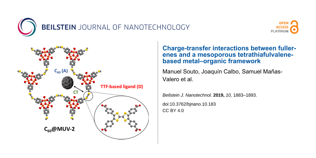
MOFs using TTF as ligands have become an interesting new class of functional porous systems since they can incorporate additional electronic features to prepare new electrically conductive and redox-active MOFs [48-51]. Very recently, we have reported a hierarchical and highly stable TTF-based MOF, named MUV-2, which is based on the 6-connected trimeric cluster [Fe3(μ3O)(COO)6] as secondary building unit (SBU) and tetratopic tetrathiafulvalene-tetrabenzoate (TTFTB4−) ligands. This MOF shows a hierarchical structure with mesoporous channels of ≈3 nm and orthogonal microporous channels of ≈1 nm. In addition, it exhibits an enhanced catalytic activity for the aerobic oxidation of dibenzothiophene in diesel [52], and a reversible continuous breathing upon adsorption of different solvents [53]. Importantly, the planarity of the TTF ligands can be modulated by the breathing behaviour, which directly impacts on its electrochemical properties [53,54]. In view of the remarkable electron-donor character of the TTF-based ligands, herein we present the encapsulation of C60 in MUV-2 (C60@MUV-2) (Figure 1). A detailed study on the CT interactions between the electron-donor TTF ligands from the framework and the electron-acceptor fullerenes has been carried out by different spectroscopic techniques and theoretical calculations. Gas sorption measurements demonstrate that permanent porosity is retained, whereas electrical measurements show that conductivity is enhanced after C60 encapsulation.
![[2190-4286-10-183-1]](/bjnano/content/figures/2190-4286-10-183-1.png?scale=2.0&max-width=1024&background=FFFFFF)
Figure 1: Schematic representation of the encapsulation of the electron-acceptor (A) C60 in the electron-donor (D) TTF-based MUV-2. Grey, yellow, orange and red spheres represent C, S, Fe and O atoms, respectively.
Figure 1: Schematic representation of the encapsulation of the electron-acceptor (A) C60 in the electron-dono...
Results and Discussion
Synthesis and characterisation of C60@MUV-2
Synthesis and encapsulation of C60 into MUV-2
MUV-2 was synthesised as previously described based on the solvothermal reaction of tetrathiafulvalene tetrabenzoic acid (H4TTFTB), the preformed cluster [Fe3O(CH3COO)6]ClO4 and acetic acid as a modulator in dimethylformamide (DMF) [52]. In order to activate the material, MUV-2 was exhaustively washed with DMF, methanol and heated at 150 °C for 2 h. Encapsulation of C60 was achieved adapting a reported procedure [36] by immersing the activated microcrystalline powder of MUV-2 in a saturated solution of C60 in o-dichlorobenzene for three days at 60 °C. Then, the material was exhaustively washed with o-dichlorobenzene in order to remove the physisorbed C60 on the MOF surface, washed with methanol and dried at 150 °C for 2 h. The powder X-ray diffraction (PXRD) pattern of C60@MUV-2 shows that the principal peak remains at 3.4° confirming that crystallinity is maintained after encapsulation of C60 and removal of the solvent (Figure 2). It is important to note that the principal peak is slightly shifted when comparing the experimental and simulated PXRD patterns. This can be explained by the breathing behaviour of MUV-2 [53]. The needle-like morphology of C60@MUV-2 also remained similar to the one of MUV-2 as confirmed by scanning electron microscopy (SEM) (Figure S1, Supporting Information File 1).
![[2190-4286-10-183-2]](/bjnano/content/figures/2190-4286-10-183-2.png?scale=2.0&max-width=1024&background=FFFFFF)
Figure 2: Powder X-ray diffraction (PXRD) patterns of simulated and experimental desolvated MUV-2 and C60@MUV-2.
Figure 2: Powder X-ray diffraction (PXRD) patterns of simulated and experimental desolvated MUV-2 and C60@MUV...
Raman and UV–vis spectroscopy
Raman spectra of C60, MUV-2 and C60@MUV-2 crystals were measured using a Raman excitation wavelength of 785 nm (Figure 3a). The presence of Raman bands at 218, 284 and 490 cm−1 evidences the encapsulation of C60 in MUV-2, whereas the broadening and shifting of the bands towards higher frequencies are indicative of the charge-transfer (CT) interactions between the electron-acceptor C60 and the electron-donor TTF ligands of the framework [36,55]. On the other hand, the UV–vis spectrum of C60@MUV-2 crystals dispersed in KBr pellets (Figure 3b) shows the presence of two new bands around 260 and 350 nm, which can be assigned to C60, whereas a broad band from 450 to 800 nm can be designated to an intermolecular CT excitation between the C60 and TTF ligands, as supported by theoretical calculations (see below). The experimental optical bandgap calculated from the onset is near 1.4 eV (885 nm), which is in agreement with the calculated electrochemical bandgap (1.43 eV) since the redox potential of TTF linkers was found to be 1.1 V (vs Ag/AgCl) [53] and the redox potential of C60 is −0.33 V (vs Ag/AgCl).
![[2190-4286-10-183-3]](/bjnano/content/figures/2190-4286-10-183-3.png?scale=2.0&max-width=1024&background=FFFFFF)
Figure 3: a) Raman spectra of C60, MUV-2 and C60@MUV-2. b) Solid-state UV–vis spectra of MUV-2 and C60@MUV-2. The spectra were recorded by dispersing the samples in KBr pellets.
Figure 3: a) Raman spectra of C60, MUV-2 and C60@MUV-2. b) Solid-state UV–vis spectra of MUV-2 and C60@MUV-2....
Gas sorption measurements
The porosity of C60@MUV-2 was studied by means of N2 and CO2 adsorption isotherm measurements (Figure 4). The measurement of nitrogen at 77 K yielded a combination of type-I and type-IV isotherms (Figure 4a), as in the case of MUV-2, indicating the presence of micropores and mesopores in the framework. C60@MUV-2 has a Brunauer–Emmett–Teller (BET) surface area of 1040 m2/g, which is slightly lower than that of MUV-2 (1190 m2/g). Thus, porosity is retained after encapsulation of C60, in agreement with other reported examples [36,56]. The pore volume decreased from 0.53 cm3/g to 0.44 cm3/g after encapsulation of C60 in MUV-2, whereas the average pore diameter calculated by means of the Barret–Joyner–Halenda (BJH) method was found to be similar in both cases (≈35 Å). The quantity of fullerene encapsulated in MUV-2 was estimated from the decrease in pore volume, obtaining a value of around 0.7 C60 per 3 TTF ligands, almost 1 fullerene per section of the void. This low encapsulation rate can be explained by diffusion issues or by weak interactions between the C60 and the framework, which are not strong enough to keep the C60 retained during the washing procedure. The CO2 isotherm on C60@MUV-2 at 298 K also showed a small decrease in the gas sorption capacity (Figure 4b), especially at high pressures (7.7 and 5.3 mmol CO2/g at 18 bar for MUV-2 and C60@MUV-2, respectively).
![[2190-4286-10-183-4]](/bjnano/content/figures/2190-4286-10-183-4.png?scale=2.0&max-width=1024&background=FFFFFF)
Figure 4: a) Nitrogen adsorption isotherms at 77 K and b) high-pressure CO2 adsorption isotherms at 298 K, on MUV-2 (black) and C60@MUV-2 (red).
Figure 4: a) Nitrogen adsorption isotherms at 77 K and b) high-pressure CO2 adsorption isotherms at 298 K, on ...
Theoretical calculations
In order to get further insight into the donor–acceptor interactions between C60 and the TTF-based MOF, theoretical calculations were performed under the density functional theory (DFT). The MUV-2 framework was modelled as previously described [53], with a high-spin Fe(III) configuration and one fullerene C60 guest molecule per pore (according to the experimental encapsulation efficiency). The host–guest system C60@MUV-2 was fully optimized under periodic boundary conditions using the PBEsol functional with dispersion corrections (see the Experimental section for details). We initially modelled the fullerene C60 guest in the middle of the MUV-2 mesopore. After several relaxation steps, the C60 was able to accommodate in one of the three cavities to interact favourably with the TTF-based ligand. We explored two possible conformations for the host–guest C60@MUV-2 system (A and B; Figure 5a, Supporting Information File 2). In conformer A, the fullerene ball remains in the void between two TTFTB ligands, approaching one of them with short C(C60)…S(TTFTB) and C(C60)…benzene(TTFTB) contacts calculated at 3.4 and 3.5 Å, respectively (Figure 5b). In conformer B, fullerene remains over the TTFTB ligand, promoting an efficient concave–convex complementarity with a large amount of noncovalent interactions between the C60 ball and the TTF core (C(C60)…S(TTFTB) distances of 3.6–3.8 Å), and stabilizing CH…π contacts between the benzene rings of TTFTB and the fullerene (2.5 Å, Figure 5). Analysis of the NCI index allows for the visualization of the noncovalent interactions between the TTFTB ligand and the C60 guest, showing a significantly larger NCI surface for conformer B compared to conformer A (Figure 5b).
![[2190-4286-10-183-5]](/bjnano/content/figures/2190-4286-10-183-5.png?scale=2.0&max-width=1024&background=FFFFFF)
Figure 5: a) Minimum-energy crystal structure calculated for conformations A and B of host–guest C60@MUV-2 at the PBEsol level under periodic boundary conditions (PBC). b) Supramolecular assemblies of C60@TTFTB extracted from the PBC-optimized C60@MUV-2 system in arrangements A and B. Intermolecular short contacts (in Å) and NCI surfaces (reduced density gradient isovalue = 0.3 a. u. (atomic units)) are displayed. Interaction energies (Eint) of −20.01 and −23.74 kcal/mol are calculated for C60@TTFTB in conformer A and B, respectively. Fullerene C60 is coloured in blue for better viewing.
Figure 5: a) Minimum-energy crystal structure calculated for conformations A and B of host–guest C60@MUV-2 at...
Accurate hybrid DFT molecular calculations including dispersion corrections were performed to quantify the total stabilization gained when C60 interacts with MUV-2 in arrangements A and B. Interaction energies (Eint) were calculated for the cluster C60@TTFTB at the B3LYP-D3/6-31G** level of theory with counterpoise correction, using the minimum-energy geometry previously obtained under periodic boundary conditions (see Experimental section). Theoretical calculations indicate that C60 favourably interacts with the TTFTB ligand, with large Eint < −20 kcal/mol in both arrangements. Conformer B, in which the fullerene is placed over the TTF moiety promoting an efficient concave–convex complementarity (Figure 5), is predicted the most stable arrangement, with an Eint value of −23.74 kcal/mol (≈4 kcal/mol more stable than conformer A). Henceforth, we focus the subsequent analysis on conformation B.
Electronic structure calculations indicate that C60@MUV-2 presents a small bandgap calculated to be 0.90 eV in spin-up or α-channel, and 0.72 eV in spin-down or β-channel (Figure 6), slightly smaller than that predicted for pristine MUV-2 (0.86 eV in β-channel) [53]. Analysis of the projected density of states (PDoS) indicates that the valence band maximum (VBM) in C60@MUV-2 corresponds to the electron-rich TTF unit (Figure 6a). The highest occupied crystal orbital (HOCO) displays the typical shape of the TTF HOMO and confirms the TTF-nature of the VBM (Figure 6b). In the α-channel, the conduction band minimum (CBM) is described by the fullerene moiety, being the lowest unoccupied crystal orbital (LUCO) completely localized on the C60 ball. Otherwise, the CBM in the β-channel is best described by the unoccupied Fe d-orbitals of the inorganic cluster of the MOF, the eigenstates corresponding to the fullerene being only 0.2 eV above in energy (Figure 6). Due to the relatively low bandgap, the nature of the frontier crystal orbitals and the close proximity between the electroactive donor TTF and acceptor C60 moieties, CT processes are expected upon light irradiation.
![[2190-4286-10-183-6]](/bjnano/content/figures/2190-4286-10-183-6.png?scale=2.0&max-width=1024&background=FFFFFF)
Figure 6: a) Projected density of states (PDoS) for the host–guest C60@MUV-2 system, with contributions from the TTF core, the secondary building unit (SBU), and the fullerene C60. The Fermi level (EF) is indicated, and the energy reference is set to vacuum. b) Highest occupied (HOCO) and lowest unoccupied (LUCO) crystal orbitals in the two spin channels for C60@MUV-2.
Figure 6: a) Projected density of states (PDoS) for the host–guest C60@MUV-2 system, with contributions from ...
Donor–acceptor interactions in C60@MUV-2 were first assessed at the ground state electronic configuration. The electron density difference between the framework interacting with C60 (C60@MUV-2) and the individual moieties (C60 + MUV-2) suggests a partial charge transfer from the TTF to the fullerene ball. Blue regions in Figure 7 indicate that the electron density is depleted from the TTF unit, especially from the S lone pairs, and is accumulated (yellow volumes) in the fullerene regions close to the TTFTB ligand. The partial charge transfer from the donor TTFTB ligand to the acceptor fullerene moiety in the ground state is calculated to be as small as 0.02e (and probably assigned to electronic polarization), with an exponential decay as a function of the C60…TTF intermolecular distance (Table S2, Supporting Information File 1).
![[2190-4286-10-183-7]](/bjnano/content/figures/2190-4286-10-183-7.png?scale=2.0&max-width=1024&background=FFFFFF)
Figure 7: Electron density difference between host–guest C60@MUV-2 and the constituting moieties (C60 + MUV-2). Blue and yellow regions indicate charge depletion and accumulation, respectively.
Figure 7: Electron density difference between host–guest C60@MUV-2 and the constituting moieties (C60 + MUV-2...
Time-dependent DFT molecular calculations were performed at the CAM-B3LYP/6-31G** level (see the Experimental section) to shed light onto the photoinduced CT process of C60@MUV-2. Figure 8 displays the simulated absorption spectra predicted for the cluster C60@TTFTB system in the most stable arrangement B, the TTFTB ligand, and the fullerene guest (the triplet excitation energies are indicated). The high-energy region (below 400 nm) of the experimental UV–vis absorption spectrum of C60@MUV-2 is dominated by the MUV-2 framework (Figure 3b). Theoretical calculations predict several intense transitions in the region below 300 nm for the TTFTB ligand (Table S3, Supporting Information File 1) that explain the experimental wide band with maximum at ≈230 nm recorded for MUV-2 and C60@MUV-2. These transitions are described by π–π* electronic promotions involving the TTF and the peripheral carboxybenzene groups in the TTFTB ligand (Table S3, Supporting Information File 1). Singlet excited states S1 and S3 are predicted with less intensity (oscillator strength f < 0.2) and are described by TTF→benzene and TTF-centred monoexcitations, respectively, and give rise to the shoulder experimentally recorded at ≈350 nm for C60@MUV-2 (Table S3, Supporting Information File 1). On the other hand, the predicted singlet excited states of fullerene S37–S39 (f ≈ 0.2) and S52–S54 (f ≈ 0.1) in the region of 280 and 260 nm (Table S3, Supporting Information File 1), respectively, correlate with the experimental features that appear at 325 and 275 nm in host–guest C60@MUV-2 (Figure 3b).
![[2190-4286-10-183-8]](/bjnano/content/figures/2190-4286-10-183-8.png?scale=2.0&max-width=1024&background=FFFFFF)
Figure 8: a) TDDFT absorption spectra calculated at the CAM-B3LYP/6-31G** level for host–guest C60@TTFTB (including vertical excitation energies), TTFTB ligand, and fullerene C60 (singlets and triplet energies). b) Monoelectronic excitation that describes the nature of the lowest-lying singlet excited state S1 of C60@TTFTB.
Figure 8: a) TDDFT absorption spectra calculated at the CAM-B3LYP/6-31G** level for host–guest C60@TTFTB (inc...
Importantly, a new singlet excitation is computed for C60@TTFTB (S1) at 578 nm, which is not predicted either for the TTFTB ligand or the fullerene C60 (Figure 8). This transition has relatively small intensity (f = 0.018), and can be described by one-electron promotion from TTF to C60, i.e., it has a CT nature (Figure 8b). The position of this CT excitation (578 nm) nicely agrees with the low-energy broad band that appears in the experimental absorption spectrum of C60@MUV-2, centred at 550 nm and expanding up to 800 nm. In fact, theoretical calculations indicate that the intensity and energy of the S1 CT transition in C60@TTFTB is significantly affected by the intermolecular TTF…C60 distance and the characteristic TTF boat dihedral angle (Table S4, Supporting Information File 1). The charge transfer from the TTF to the fullerene ball in the S1 CT excitation of C60@TTFTB is calculated to be of nearly 1e (0.94e at the minimum-energy geometry, Table S2, Supporting Information File 1).
Electrical measurements
In order to analyse the possible enhancement of electrical conductivity after encapsulation of C60 in MUV-2, transport measurements for MUV-2 and C60@MUV-2 were performed using two-contact probe pressed-pellet devices measured at room temperature (300 K) (Figure 9). Interestingly, the pellet of C60@MUV-2 shows an increase of around two orders of magnitude (σ = 4.7·10−9 S/cm) compared to the very resistive MUV-2 (σ = 3.7·10−11 S/cm, Table 1). This enhancement of the electrical conductivity can be explained by the donor–acceptor charge transfer from the TTF linkers to C60 since the fullerene is acting as a dopant introducing charge carriers within the framework. However, this enhancement in conductivity is lower in comparison to other reported systems [14,35] probably due to the low ratio between C60 and TTF (1:4) and the long distances between the TTF moieties (9.6 Å along the c-axis), which could prevent the charge delocalisation along the framework.
![[2190-4286-10-183-9]](/bjnano/content/figures/2190-4286-10-183-9.png?scale=2.0&max-width=1024&background=FFFFFF)
Figure 9: Current (I)–Voltage (V) plot for pressed pellets of MUV-2 (black) and C60@MUV-2 (red) at 300 K.
Figure 9: Current (I)–Voltage (V) plot for pressed pellets of MUV-2 (black) and C60@MUV-2 (red) at 300 K.
Table 1: Geometrical factors (length l, width w, and thickness t), resistance obtained by the linear fit of the ohmic regime of the I–V curves and conductivity for MUV-2 and C60@MUV-2, at 300 K.
| sample | l (μm) | w (μm) | t (μm) | R (Ω) at 300 K | σ (S/cm) at 300 K |
|---|---|---|---|---|---|
| MUV-2 | 110 | 480 | 65 | (9.5 ± 0.6)·1011 | 3.7·10−11 |
| C60@MUV-2 | 325 | 540 | 150 | (8.510 ± 0.015)·109 | 4.7·10−9 |
Conclusion
In summary, we have reported for the first time the encapsulation of C60 in a mesoporous TTF-based MOF (MUV-2). Charge-transfer interactions between C60 and TTF ligands from the framework in C60@MUV-2 were confirmed by different spectroscopic techniques and theoretical calculations. Interestingly, after encapsulation of fullerenes, gas sorption measurements demonstrated that the mesoporosity of the MOF is maintained, and electrical measurements revealed an increase of around two orders of magnitude in conductivity, which can be explained by CT donor–acceptor (TTF→C60) interactions. Current research is focused on the improvement of the electrical conductivity in MUV-2 and the photophysical characterisation of the charge transfer process in C60@MUV-2.
Experimental
General methods and materials: All reagents and solvents employed for the syntheses were of high purity and were purchased from Sigma-Aldrich Co., and TCI. Powder X-ray diffraction patterns were recorded using 0.7 mm borosilicate capillaries that were aligned on an Empyrean PANalytical powder diffractometer, using Cu Kα radiation (λ = 1.54056 Å). Raman spectra were acquired with a micro-Raman (model XploRA ONE from Horiba, Kyoto, Japan) with a grating of 1200 gr/mm and a wavelength of 785 nm. UV–vis absorption spectra were recorded on a Jasco V-670 spectrophotometer in baseline mode from 400 to 800 nm range. The absorption spectra were measured on the solid state by dispersing the crystals in KBr pellets. Nitrogen adsorption isotherms were measured using a TriStar II PLUS apparatus (Micromeritics) at 77 K. The BET surface area was calculated by using the Brunauer–Emmett–Teller equation. The high-pressure CO2 adsorption isotherms were measured in a IGA-100 gravimetric sorption analyzer (Hiden Isochema) and the sample was degassed for 2 h at 150 °C in vacuum.
Synthesis of MUV-2 and encapsulation of C60: MUV-2 was synthesised and characterised as previously reported [52]. Then, 30 mg of fullerene (C60) was dissolved in 2 mL of o-dichlorobenzene and activated MUV-2 (10 mg) was added to it. The vial was heated at 60 °C for 3 days and the MOF was then exhaustively washed with o-dichlorobenzene to remove any physisorbed C60 on the MOF surface, washed with methanol and finally dried at 150 °C for 2 h.
Computational details: Theoretical calculations were performed under the density functional theory framework. Periodic boundary conditions (PBC) calculations were carried out with the FHI-AIMS (Version 171221) software [57]. MUV-2 was modelled as previously described, with Fe(III) ions in a high-spin d5-configuration. The guest C60 molecule was rationally inserted into the bigger mesoporous channel of MUV-2 in the most plausible sites, and the geometry of the host–guest C60@MUV-2 system was fully relaxed at the PBEsol functional [58] with tier-1 basis set. Dispersion corrections were added according to the Hirshfeld partitioning of the electron density (Tkatchenko–Scheffler method) [59]. Electronic structure calculations were performed for band structure analysis using the hybrid HSE06 functional [60] and tier-1 basis set. Energy reference was set to vacuum according to the protocol reported by Butler and co-workers [61]. Crystal structures, crystal orbitals and electron density differences were plotted by means of VESTA (version 3.4.6) software [62]. NonCovalent Index (NCI) calculations were performed under the NCIPLOT-3.0 software [63,64] using the default PROMOLECULAR atomic densities, and density and gradient thresholds. The intermolecular contribution to the NCI surfaces was calculated by means of the INTERMOLECULAR keyword, and the VMD-1.9.3 software [65] was employed for graphical display. Molecular DFT calculations were performed for the C60@TTFTB system using the Gaussian-16.A03 suite of packages [66]. Hydrogen atoms were added in the terminal carboxylate groups for charge neutrality. Interaction energies were calculated for the previously PBC-optimized crystal structures as the energy difference between the dimer and the constituting monomers. The hybrid B3LYP [67] with the Grimme’s D3 dispersion correction [68] (B3LYP-D3) was employed along with the 6-31G** basis set and half of the counterpoise correction (CP) [69]. The consistency of the interaction energy trends at the B3LYP-D3/6-31G**+½CP level was confirmed by using other basis set or CP weights (Table S1, Supporting Information File 1). Time-dependent DFT (TDDFT) calculations were performed using the coulomb-attenuating CAM-B3LYP approach [70] with the 6-31G** basis set for the lowest-lying excited states. The B3LYP functional was also tested, but the characteristic charge-transfer excitation was largely underestimated (Figure S4, Supporting Information File 1). Excitation energies were convoluted with Gaussian functions with full-width-at-half-maximum (FWHM) of 0.2 eV. Charge transfer was evaluated as the accumulated natural population analysis (NPA) [71] charges on each moiety. Molecular orbitals were represented by means of the Chemcraft 1.7 software [72].
Electrical measurements: Pressed pellets (F ≈ 5 US tons) were cut in rectangular shapes and contacted with silver conductive paint (RS 123-9911) and platinum wires (Goodfellow, 99.99%, 25 μm of diameter) in a four-probe configuration (Figure S2 and Figure S3, Supporting Information File 1). The geometrical factors (thickness, width and length were measured using an optical microscope (width and length were determined from the top view, Figure S2a and Figure S3a, and the thickness from the lateral view, Figure S2b and Figure S3b). I–V curves were measured with a Keithley 6517B electrometer for ultra-high resistance/ultra-low current measurements in a two-probe configuration, i.e., applying a voltage bias between two leads and measuring the current between them.
Supporting Information
| Supporting Information File 1: Additional figures and tables. | ||
| Format: PDF | Size: 886.0 KB | Download |
| Supporting Information File 2:
CIF files of simulated structures of C60@MUV-2.
The ZIP archive contains CIF files of the simulated structures of C60@MUV-2 in conformation A and in conformation B. |
||
| Format: ZIP | Size: 8.6 KB | Download |
Acknowledgements
This work has been supported by the European Union (ERC-2016-CoG 724681-S-CAGE) and the Spanish MICINN (CTQ2017-89528-P). G.M.E. and M.S. thank MICINN for a Ramón y Cajal and a Juan de la Cierva-Formación fellowships, respectively. J.C. acknowledges the Generalitat Valenciana for the postdoctoral APOSTD/2017/081 fellowship. Via our membership of the UK's HEC Materials Chemistry Consortium, which is funded by EPSRC (EP/L000202), this work used the ARCHER UK National Supercomputing Service (http://www.archer.ac.uk).
References
-
Zhou, H.-C.; Long, J. R.; Yaghi, O. M. Chem. Rev. 2012, 112, 673–674. doi:10.1021/cr300014x
Return to citation in text: [1] -
Maurin, G.; Serre, C.; Cooper, A.; Férey, G. Chem. Soc. Rev. 2017, 46, 3104–3107. doi:10.1039/c7cs90049j
Return to citation in text: [1] -
Furukawa, H.; Cordova, K. E.; O'Keeffe, M.; Yaghi, O. M. Science 2013, 341, No. 1230444. doi:10.1126/science.1230444
Return to citation in text: [1] -
Slater, A. G.; Cooper, A. I. Science 2015, 348, aaa8075. doi:10.1126/science.aaa8075
Return to citation in text: [1] -
Rogge, S. M. J.; Bavykina, A.; Hajek, J.; Garcia, H.; Olivos-Suarez, A. I.; Sepúlveda-Escribano, A.; Vimont, A.; Clet, G.; Bazin, P.; Kapteijn, F.; Daturi, M.; Ramos-Fernandez, E. V.; Llabrés i Xamena, F. X.; Van Speybroeck, V.; Gascon, J. Chem. Soc. Rev. 2017, 46, 3134–3184. doi:10.1039/c7cs00033b
Return to citation in text: [1] -
Sun, L.; Campbell, M. G.; Dincǎ, M. Angew. Chem., Int. Ed. 2016, 55, 3566–3579. doi:10.1002/anie.201506219
Return to citation in text: [1] [2] -
Stassen, I.; Burtch, N.; Talin, A.; Falcaro, P.; Allendorf, M.; Ameloot, R. Chem. Soc. Rev. 2017, 46, 3185–3241. doi:10.1039/c7cs00122c
Return to citation in text: [1] -
Medina, D. D.; Mähringer, A.; Bein, T. Isr. J. Chem. 2018, 58, 1089–1101. doi:10.1002/ijch.201800110
Return to citation in text: [1] -
Campbell, M. G.; Sheberla, D.; Liu, S. F.; Swager, T. M.; Dincă, M. Angew. Chem., Int. Ed. 2015, 54, 4349–4352. doi:10.1002/anie.201411854
Return to citation in text: [1] -
Wu, G.; Huang, J.; Zang, Y.; He, J.; Xu, G. J. Am. Chem. Soc. 2017, 139, 1360–1363. doi:10.1021/jacs.6b08511
Return to citation in text: [1] -
Sheberla, D.; Bachman, J. C.; Elias, J. S.; Sun, C.-J.; Shao-Horn, Y.; Dincă, M. Nat. Mater. 2017, 16, 220–224. doi:10.1038/nmat4766
Return to citation in text: [1] -
Talin, A. A.; Centrone, A.; Ford, A. C.; Foster, M. E.; Stavila, V.; Haney, P.; Kinney, R. A.; Szalai, V.; El Gabaly, F.; Yoon, H. P.; Léonard, F.; Allendorf, M. D. Science 2014, 343, 66–69. doi:10.1126/science.1246738
Return to citation in text: [1] -
Bhardwaj, S. K.; Bhardwaj, N.; Kaur, R.; Mehta, J.; Sharma, A. L.; Kim, K.-H.; Deep, A. J. Mater. Chem. A 2018, 6, 14992–15009. doi:10.1039/c8ta04220a
Return to citation in text: [1] -
Kung, C.-W.; Otake, K.; Buru, C. T.; Goswami, S.; Cui, Y.; Hupp, J. T.; Spokoyny, A. M.; Farha, O. K. J. Am. Chem. Soc. 2018, 140, 3871–3875. doi:10.1021/jacs.8b00605
Return to citation in text: [1] [2] -
D'Alessandro, D. M. Chem. Commun. 2016, 52, 8957–8971. doi:10.1039/c6cc00805d
Return to citation in text: [1] -
Kung, C.-W.; Wang, T. C.; Mondloch, J. E.; Fairen-Jimenez, D.; Gardner, D. M.; Bury, W.; Klingsporn, J. M.; Barnes, J. C.; Van Duyne, R.; Stoddart, J. F.; Wasielewski, M. R.; Farha, O. K.; Hupp, J. T. Chem. Mater. 2013, 25, 5012–5017. doi:10.1021/cm403726v
Return to citation in text: [1] -
Chen, Q.; Sun, J.; Li, P.; Hod, I.; Moghadam, P. Z.; Kean, Z. S.; Snurr, R. Q.; Hupp, J. T.; Farha, O. K.; Stoddart, J. F. J. Am. Chem. Soc. 2016, 138, 14242–14245. doi:10.1021/jacs.6b09880
Return to citation in text: [1] -
Calbo, J.; Golomb, M. J.; Walsh, A. J. Mater. Chem. A 2019, 7, 16571–16597. doi:10.1039/c9ta04680a
Return to citation in text: [1] -
Van Wyk, A.; Smith, T.; Park, J.; Deria, P. J. Am. Chem. Soc. 2018, 140, 2756–2760. doi:10.1021/jacs.7b13211
Return to citation in text: [1] -
Hua, C.; Doheny, P. W.; Ding, B.; Chan, B.; Yu, M.; Kepert, C. J.; D’Alessandro, D. M. J. Am. Chem. Soc. 2018, 140, 6622–6630. doi:10.1021/jacs.8b02638
Return to citation in text: [1] -
Miyasaka, H. Acc. Chem. Res. 2013, 46, 248–257. doi:10.1021/ar300102t
Return to citation in text: [1] -
Xiao, J.-D.; Han, L.; Luo, J.; Yu, S.-H.; Jiang, H.-L. Angew. Chem., Int. Ed. 2018, 57, 1103–1107. doi:10.1002/anie.201711725
Return to citation in text: [1] -
Fang, X.; Shang, Q.; Wang, Y.; Jiao, L.; Yao, T.; Li, Y.; Zhang, Q.; Luo, Y.; Jiang, H.-L. Adv. Mater. (Weinheim, Ger.) 2018, 30, 1705112. doi:10.1002/adma.201705112
Return to citation in text: [1] -
Xiao, J.-D.; Jiang, H.-L. Acc. Chem. Res. 2019, 52, 356–366. doi:10.1021/acs.accounts.8b00521
Return to citation in text: [1] -
Kroto, H. W.; Heath, J. R.; O'Brien, S. C.; Curl, R. F.; Smalley, R. E. Nature 1985, 318, 162–163. doi:10.1038/318162a0
Return to citation in text: [1] -
Giacalone, F.; Martín, N. Chem. Rev. 2006, 106, 5136–5190. doi:10.1021/cr068389h
Return to citation in text: [1] -
Martín, N. Chem. Commun. 2006, 2093–2104. doi:10.1039/b601582b
Return to citation in text: [1] -
Zieleniewska, A.; Lodermeyer, F.; Roth, A.; Guldi, D. M. Chem. Soc. Rev. 2018, 47, 702–714. doi:10.1039/c7cs00728k
Return to citation in text: [1] -
Meng, H.; Wang, C.; Wang, T. Gen. Chem. 2018, 4, 180019. doi:10.21127/yaoyigc20180019
Return to citation in text: [1] -
Inokuma, Y.; Arai, T.; Fujita, M. Nat. Chem. 2010, 2, 780–783. doi:10.1038/nchem.742
Return to citation in text: [1] -
García-Simón, C.; Garcia-Borràs, M.; Gómez, L.; Parella, T.; Osuna, S.; Juanhuix, J.; Imaz, I.; Maspoch, D.; Costas, M.; Ribas, X. Nat. Commun. 2014, 5, 5557. doi:10.1038/ncomms6557
Return to citation in text: [1] -
García-Simón, C.; Costas, M.; Ribas, X. Chem. Soc. Rev. 2016, 45, 40–62. doi:10.1039/c5cs00315f
Return to citation in text: [1] -
Feng, Y.; Wang, T.; Li, Y.; Li, J.; Wu, J.; Wu, B.; Jiang, L.; Wang, C. J. Am. Chem. Soc. 2015, 137, 15055–15060. doi:10.1021/jacs.5b10796
Return to citation in text: [1] -
Meng, H.; Zhao, C.; Nie, M.; Wang, C.; Wang, T. J. Phys. Chem. C 2019, 123, 6265–6269. doi:10.1021/acs.jpcc.8b11659
Return to citation in text: [1] -
Liu, X.; Kozlowska, M.; Okkali, T.; Wagner, D.; Higashino, T.; Brenner-Weiß, G.; Marschner, S. M.; Fu, Z.; Zhang, Q.; Imahori, H.; Bräse, S.; Wenzel, W.; Wöll, C.; Heinke, L. Angew. Chem., Int. Ed. 2019, 58, 9590–9595. doi:10.1002/anie.201904475
Return to citation in text: [1] [2] -
Goswami, S.; Ray, D.; Otake, K.-i.; Kung, C.-W.; Garibay, S. J.; Islamoglu, T.; Atilgan, A.; Cui, Y.; Cramer, C. J.; Farha, O. K.; Hupp, J. T. Chem. Sci. 2018, 9, 4477–4482. doi:10.1039/c8sc00961a
Return to citation in text: [1] [2] [3] [4] -
Segura, J. L.; Martín, N. Angew. Chem., Int. Ed. 2001, 40, 1372–1409. doi:10.1002/1521-3773(20010417)40:8<1372::aid-anie1372>3.0.co;2-i
Return to citation in text: [1] -
Martín, N. Chem. Commun. 2013, 49, 7025–7027. doi:10.1039/c3cc00240c
Return to citation in text: [1] -
Jana, A.; Bähring, S.; Ishida, M.; Goeb, S.; Canevet, D.; Sallé, M.; Jeppesen, J. O.; Sessler, J. L. Chem. Soc. Rev. 2018, 47, 5614–5645. doi:10.1039/c8cs00035b
Return to citation in text: [1] -
Spruell, J. M.; Coskun, A.; Friedman, D. C.; Forgan, R. S.; Sarjeant, A. A.; Trabolsi, A.; Fahrenbach, A. C.; Barin, G.; Paxton, W. F.; Dey, S. K.; Olson, M. A.; Benítez, D.; Tkatchouk, E.; Colvin, M. T.; Carmielli, R.; Caldwell, S. T.; Rosair, G. M.; Hewage, S. G.; Duclairoir, F.; Seymour, J. L.; Slawin, A. M. Z.; Goddard, W. A., III; Wasielewski, M. R.; Cooke, G.; Stoddart, J. F. Nat. Chem. 2010, 2, 870–879. doi:10.1038/nchem.749
Return to citation in text: [1] -
Frasconi, M.; Kikuchi, T.; Cao, D.; Wu, Y.; Liu, W.-G.; Dyar, S. M.; Barin, G.; Sarjeant, A. A.; Stern, C. L.; Carmieli, R.; Wang, C.; Wasielewski, M. R.; Goddard, W. A., III; Stoddart, J. F. J. Am. Chem. Soc. 2014, 136, 11011–11026. doi:10.1021/ja504662a
Return to citation in text: [1] -
Pérez, E. M.; Sánchez, L.; Fernández, G.; Martín, N. J. Am. Chem. Soc. 2006, 128, 7172–7173. doi:10.1021/ja0621389
Return to citation in text: [1] -
Pérez, E. M.; Sierra, M.; Sánchez, L.; Torres, M. R.; Viruela, R.; Viruela, P. M.; Ortí, E.; Martín, N. Angew. Chem., Int. Ed. 2007, 46, 1847–1851. doi:10.1002/anie.200604327
Return to citation in text: [1] -
Pérez, E. M.; Martín, N. Chem. Soc. Rev. 2008, 37, 1512–1519. doi:10.1039/b802589b
Return to citation in text: [1] -
Canevet, D.; Pérez, E. M.; Martín, N. Angew. Chem., Int. Ed. 2011, 50, 9248–9259. doi:10.1002/anie.201101297
Return to citation in text: [1] -
Goeb, S.; Bivaud, S.; Dron, P. I.; Balandier, J. Y.; Chas, M.; Sallé, M. Chem. Commun. 2012, 48, 3106–3108. doi:10.1039/c2cc00065b
Return to citation in text: [1] -
Gallego, M.; Calbo, J.; Aragó, J.; Krickcalderon, R. M.; Liquido, F. H.; Iwamoto, T.; Greene, A. K.; Jackson, E. A.; Pérez, E. M.; Ortí, E.; Guldi, D. M.; Scott, L. T.; Martín, N. Angew. Chem., Int. Ed. 2014, 53, 2170–2175. doi:10.1002/anie.201309672
Return to citation in text: [1] -
Wang, H.-Y.; Cui, L.; Xie, J.-Z.; Leong, C. F.; D’Alessandro, D. M.; Zuo, J.-L. Coord. Chem. Rev. 2017, 345, 342–361. doi:10.1016/j.ccr.2016.10.011
Return to citation in text: [1] -
Park, S. S.; Hontz, E. R.; Sun, L.; Hendon, C. H.; Walsh, A.; Van Voorhis, T.; Dincǎ, M. J. Am. Chem. Soc. 2015, 137, 1774–1777. doi:10.1021/ja512437u
Return to citation in text: [1] -
Su, J.; Yuan, S.; Wang, H.-Y.; Huang, L.; Ge, J.-Y.; Joseph, E.; Qin, J.; Cagin, T.; Zuo, J.-L.; Zhou, H.-C. Nat. Commun. 2017, 8, 2008. doi:10.1038/s41467-017-02256-y
Return to citation in text: [1] -
Wang, H.-Y.; Ge, J.-Y.; Hua, C.; Jiao, C.-Q.; Wu, Y.; Leong, C. F.; D'Alessandro, D. M.; Liu, T.; Zuo, J.-L. Angew. Chem., Int. Ed. 2017, 56, 5465–5470. doi:10.1002/anie.201611824
Return to citation in text: [1] -
Souto, M.; Santiago-Portillo, A.; Palomino, M.; Vitórica-Yrezábal, I. J.; Vieira, B. J. C.; Waerenborgh, J. C.; Valencia, S.; Navalón, S.; Rey, F.; García, H.; Mínguez Espallargas, G. Chem. Sci. 2018, 9, 2413–2418. doi:10.1039/c7sc04829g
Return to citation in text: [1] [2] [3] -
Souto, M.; Romero, J.; Calbo, J.; Vitórica-Yrezábal, I. J.; Zafra, J. L.; Casado, J.; Ortí, E.; Walsh, A.; Mínguez Espallargas, G. J. Am. Chem. Soc. 2018, 140, 10562–10569. doi:10.1021/jacs.8b05890
Return to citation in text: [1] [2] [3] [4] [5] [6] -
Vicent-Morales, M.; Vitórica-Yrezábal, I. J.; Souto, M.; Mínguez Espallargas, G. CrystEngComm 2019, 21, 3031–3035. doi:10.1039/c9ce00233b
Return to citation in text: [1] -
Chae, H. K.; Siberio-Pérez, D. Y.; Kim, J.; Go, Y.; Eddaoudi, M.; Matzger, A. J.; O’Keeffe, M.; Yaghi, O. M. Nature 2004, 427, 523–527. doi:10.1038/nature02311
Return to citation in text: [1] -
Li, H.; Hill, M. R.; Huang, R.; Doblin, C.; Lim, S.; Hill, A. J.; Babarao, R.; Falcaro, P. Chem. Commun. 2016, 52, 5973–5976. doi:10.1039/c6cc01620k
Return to citation in text: [1] -
Blum, V.; Gehrke, R.; Hanke, F.; Havu, P.; Havu, V.; Ren, X.; Reuter, K.; Scheffler, M. Comput. Phys. Commun. 2009, 180, 2175–2196. doi:10.1016/j.cpc.2009.06.022
Return to citation in text: [1] -
Perdew, J. P.; Ruzsinszky, A.; Csonka, G. I.; Vydrov, O. A.; Scuseria, G. E.; Constantin, L. A.; Zhou, X.; Burke, K. Phys. Rev. Lett. 2008, 100, 136406. doi:10.1103/physrevlett.100.136406
Return to citation in text: [1] -
Tkatchenko, A.; Scheffler, M. Phys. Rev. Lett. 2009, 102, 073005. doi:10.1103/physrevlett.102.073005
Return to citation in text: [1] -
Heyd, J.; Scuseria, G. E.; Ernzerhof, M. J. Chem. Phys. 2003, 118, 8207–8215. doi:10.1063/1.1564060
Return to citation in text: [1] -
Butler, K. T.; Hendon, C. H.; Walsh, A. J. Am. Chem. Soc. 2014, 136, 2703–2706. doi:10.1021/ja4110073
Return to citation in text: [1] -
Momma, K.; Izumi, F. J. Appl. Crystallogr. 2011, 44, 1272–1276. doi:10.1107/s0021889811038970
Return to citation in text: [1] -
Johnson, E. R.; Keinan, S.; Mori-Sánchez, P.; Contreras-García, J.; Cohen, A. J.; Yang, W. J. Am. Chem. Soc. 2010, 132, 6498–6506. doi:10.1021/ja100936w
Return to citation in text: [1] -
Contreras-García, J.; Johnson, E. R.; Keinan, S.; Chaudret, R.; Piquemal, J.-P.; Beratan, D. N.; Yang, W. J. Chem. Theory Comput. 2011, 7, 625–632. doi:10.1021/ct100641a
Return to citation in text: [1] -
Humphrey, W.; Dalke, A.; Schulten, K. J. Mol. Graphics 1996, 14, 33–38. doi:10.1016/0263-7855(96)00018-5
Return to citation in text: [1] -
Gaussian 16, Revision A.03; Gaussian, Inc.: Wallingford CT, USA, 2016.
Return to citation in text: [1] -
Becke, A. D. J. Chem. Phys. 1993, 98, 5648–5652. doi:10.1063/1.464913
Return to citation in text: [1] -
Grimme, S.; Ehrlich, S.; Goerigk, L. J. Comput. Chem. 2011, 32, 1456–1465. doi:10.1002/jcc.21759
Return to citation in text: [1] -
Boys, S. F.; Bernardi, F. Mol. Phys. 1970, 19, 553–566. doi:10.1080/00268977000101561
Return to citation in text: [1] -
Yanai, T.; Tew, D. P.; Handy, N. C. Chem. Phys. Lett. 2004, 393, 51–57. doi:10.1016/j.cplett.2004.06.011
Return to citation in text: [1] -
Weinhold, F.; Carpenter, J. E. The Natural Bond Orbital Lewis Structure Concept for Molecules, Radicals and Radical Ions. In The Structure of Small Molecules and Ions; Naaman, R.; Vager, Z., Eds.; Springer: Boston, MA, USA, 1988; pp 227–236. doi:10.1007/978-1-4684-7424-4_24
Return to citation in text: [1] -
Chemcraft - graphical software for visualization of quantum chemistry computations. https://www.chemcraftprog.com (accessed June 27, 2019).
Return to citation in text: [1]
| 53. | Souto, M.; Romero, J.; Calbo, J.; Vitórica-Yrezábal, I. J.; Zafra, J. L.; Casado, J.; Ortí, E.; Walsh, A.; Mínguez Espallargas, G. J. Am. Chem. Soc. 2018, 140, 10562–10569. doi:10.1021/jacs.8b05890 |
| 36. | Goswami, S.; Ray, D.; Otake, K.-i.; Kung, C.-W.; Garibay, S. J.; Islamoglu, T.; Atilgan, A.; Cui, Y.; Cramer, C. J.; Farha, O. K.; Hupp, J. T. Chem. Sci. 2018, 9, 4477–4482. doi:10.1039/c8sc00961a |
| 56. | Li, H.; Hill, M. R.; Huang, R.; Doblin, C.; Lim, S.; Hill, A. J.; Babarao, R.; Falcaro, P. Chem. Commun. 2016, 52, 5973–5976. doi:10.1039/c6cc01620k |
| 53. | Souto, M.; Romero, J.; Calbo, J.; Vitórica-Yrezábal, I. J.; Zafra, J. L.; Casado, J.; Ortí, E.; Walsh, A.; Mínguez Espallargas, G. J. Am. Chem. Soc. 2018, 140, 10562–10569. doi:10.1021/jacs.8b05890 |
| 1. | Zhou, H.-C.; Long, J. R.; Yaghi, O. M. Chem. Rev. 2012, 112, 673–674. doi:10.1021/cr300014x |
| 2. | Maurin, G.; Serre, C.; Cooper, A.; Férey, G. Chem. Soc. Rev. 2017, 46, 3104–3107. doi:10.1039/c7cs90049j |
| 10. | Wu, G.; Huang, J.; Zang, Y.; He, J.; Xu, G. J. Am. Chem. Soc. 2017, 139, 1360–1363. doi:10.1021/jacs.6b08511 |
| 33. | Feng, Y.; Wang, T.; Li, Y.; Li, J.; Wu, J.; Wu, B.; Jiang, L.; Wang, C. J. Am. Chem. Soc. 2015, 137, 15055–15060. doi:10.1021/jacs.5b10796 |
| 34. | Meng, H.; Zhao, C.; Nie, M.; Wang, C.; Wang, T. J. Phys. Chem. C 2019, 123, 6265–6269. doi:10.1021/acs.jpcc.8b11659 |
| 35. | Liu, X.; Kozlowska, M.; Okkali, T.; Wagner, D.; Higashino, T.; Brenner-Weiß, G.; Marschner, S. M.; Fu, Z.; Zhang, Q.; Imahori, H.; Bräse, S.; Wenzel, W.; Wöll, C.; Heinke, L. Angew. Chem., Int. Ed. 2019, 58, 9590–9595. doi:10.1002/anie.201904475 |
| 60. | Heyd, J.; Scuseria, G. E.; Ernzerhof, M. J. Chem. Phys. 2003, 118, 8207–8215. doi:10.1063/1.1564060 |
| 9. | Campbell, M. G.; Sheberla, D.; Liu, S. F.; Swager, T. M.; Dincă, M. Angew. Chem., Int. Ed. 2015, 54, 4349–4352. doi:10.1002/anie.201411854 |
| 36. | Goswami, S.; Ray, D.; Otake, K.-i.; Kung, C.-W.; Garibay, S. J.; Islamoglu, T.; Atilgan, A.; Cui, Y.; Cramer, C. J.; Farha, O. K.; Hupp, J. T. Chem. Sci. 2018, 9, 4477–4482. doi:10.1039/c8sc00961a |
| 61. | Butler, K. T.; Hendon, C. H.; Walsh, A. J. Am. Chem. Soc. 2014, 136, 2703–2706. doi:10.1021/ja4110073 |
| 6. | Sun, L.; Campbell, M. G.; Dincǎ, M. Angew. Chem., Int. Ed. 2016, 55, 3566–3579. doi:10.1002/anie.201506219 |
| 7. | Stassen, I.; Burtch, N.; Talin, A.; Falcaro, P.; Allendorf, M.; Ameloot, R. Chem. Soc. Rev. 2017, 46, 3185–3241. doi:10.1039/c7cs00122c |
| 8. | Medina, D. D.; Mähringer, A.; Bein, T. Isr. J. Chem. 2018, 58, 1089–1101. doi:10.1002/ijch.201800110 |
| 29. | Meng, H.; Wang, C.; Wang, T. Gen. Chem. 2018, 4, 180019. doi:10.21127/yaoyigc20180019 |
| 58. | Perdew, J. P.; Ruzsinszky, A.; Csonka, G. I.; Vydrov, O. A.; Scuseria, G. E.; Constantin, L. A.; Zhou, X.; Burke, K. Phys. Rev. Lett. 2008, 100, 136406. doi:10.1103/physrevlett.100.136406 |
| 3. | Furukawa, H.; Cordova, K. E.; O'Keeffe, M.; Yaghi, O. M. Science 2013, 341, No. 1230444. doi:10.1126/science.1230444 |
| 4. | Slater, A. G.; Cooper, A. I. Science 2015, 348, aaa8075. doi:10.1126/science.aaa8075 |
| 5. | Rogge, S. M. J.; Bavykina, A.; Hajek, J.; Garcia, H.; Olivos-Suarez, A. I.; Sepúlveda-Escribano, A.; Vimont, A.; Clet, G.; Bazin, P.; Kapteijn, F.; Daturi, M.; Ramos-Fernandez, E. V.; Llabrés i Xamena, F. X.; Van Speybroeck, V.; Gascon, J. Chem. Soc. Rev. 2017, 46, 3134–3184. doi:10.1039/c7cs00033b |
| 30. | Inokuma, Y.; Arai, T.; Fujita, M. Nat. Chem. 2010, 2, 780–783. doi:10.1038/nchem.742 |
| 31. | García-Simón, C.; Garcia-Borràs, M.; Gómez, L.; Parella, T.; Osuna, S.; Juanhuix, J.; Imaz, I.; Maspoch, D.; Costas, M.; Ribas, X. Nat. Commun. 2014, 5, 5557. doi:10.1038/ncomms6557 |
| 32. | García-Simón, C.; Costas, M.; Ribas, X. Chem. Soc. Rev. 2016, 45, 40–62. doi:10.1039/c5cs00315f |
| 59. | Tkatchenko, A.; Scheffler, M. Phys. Rev. Lett. 2009, 102, 073005. doi:10.1103/physrevlett.102.073005 |
| 19. | Van Wyk, A.; Smith, T.; Park, J.; Deria, P. J. Am. Chem. Soc. 2018, 140, 2756–2760. doi:10.1021/jacs.7b13211 |
| 20. | Hua, C.; Doheny, P. W.; Ding, B.; Chan, B.; Yu, M.; Kepert, C. J.; D’Alessandro, D. M. J. Am. Chem. Soc. 2018, 140, 6622–6630. doi:10.1021/jacs.8b02638 |
| 21. | Miyasaka, H. Acc. Chem. Res. 2013, 46, 248–257. doi:10.1021/ar300102t |
| 22. | Xiao, J.-D.; Han, L.; Luo, J.; Yu, S.-H.; Jiang, H.-L. Angew. Chem., Int. Ed. 2018, 57, 1103–1107. doi:10.1002/anie.201711725 |
| 23. | Fang, X.; Shang, Q.; Wang, Y.; Jiao, L.; Yao, T.; Li, Y.; Zhang, Q.; Luo, Y.; Jiang, H.-L. Adv. Mater. (Weinheim, Ger.) 2018, 30, 1705112. doi:10.1002/adma.201705112 |
| 24. | Xiao, J.-D.; Jiang, H.-L. Acc. Chem. Res. 2019, 52, 356–366. doi:10.1021/acs.accounts.8b00521 |
| 26. | Giacalone, F.; Martín, N. Chem. Rev. 2006, 106, 5136–5190. doi:10.1021/cr068389h |
| 27. | Martín, N. Chem. Commun. 2006, 2093–2104. doi:10.1039/b601582b |
| 52. | Souto, M.; Santiago-Portillo, A.; Palomino, M.; Vitórica-Yrezábal, I. J.; Vieira, B. J. C.; Waerenborgh, J. C.; Valencia, S.; Navalón, S.; Rey, F.; García, H.; Mínguez Espallargas, G. Chem. Sci. 2018, 9, 2413–2418. doi:10.1039/c7sc04829g |
| 15. | D'Alessandro, D. M. Chem. Commun. 2016, 52, 8957–8971. doi:10.1039/c6cc00805d |
| 16. | Kung, C.-W.; Wang, T. C.; Mondloch, J. E.; Fairen-Jimenez, D.; Gardner, D. M.; Bury, W.; Klingsporn, J. M.; Barnes, J. C.; Van Duyne, R.; Stoddart, J. F.; Wasielewski, M. R.; Farha, O. K.; Hupp, J. T. Chem. Mater. 2013, 25, 5012–5017. doi:10.1021/cm403726v |
| 17. | Chen, Q.; Sun, J.; Li, P.; Hod, I.; Moghadam, P. Z.; Kean, Z. S.; Snurr, R. Q.; Hupp, J. T.; Farha, O. K.; Stoddart, J. F. J. Am. Chem. Soc. 2016, 138, 14242–14245. doi:10.1021/jacs.6b09880 |
| 18. | Calbo, J.; Golomb, M. J.; Walsh, A. J. Mater. Chem. A 2019, 7, 16571–16597. doi:10.1039/c9ta04680a |
| 28. | Zieleniewska, A.; Lodermeyer, F.; Roth, A.; Guldi, D. M. Chem. Soc. Rev. 2018, 47, 702–714. doi:10.1039/c7cs00728k |
| 57. | Blum, V.; Gehrke, R.; Hanke, F.; Havu, P.; Havu, V.; Ren, X.; Reuter, K.; Scheffler, M. Comput. Phys. Commun. 2009, 180, 2175–2196. doi:10.1016/j.cpc.2009.06.022 |
| 6. | Sun, L.; Campbell, M. G.; Dincǎ, M. Angew. Chem., Int. Ed. 2016, 55, 3566–3579. doi:10.1002/anie.201506219 |
| 12. | Talin, A. A.; Centrone, A.; Ford, A. C.; Foster, M. E.; Stavila, V.; Haney, P.; Kinney, R. A.; Szalai, V.; El Gabaly, F.; Yoon, H. P.; Léonard, F.; Allendorf, M. D. Science 2014, 343, 66–69. doi:10.1126/science.1246738 |
| 13. | Bhardwaj, S. K.; Bhardwaj, N.; Kaur, R.; Mehta, J.; Sharma, A. L.; Kim, K.-H.; Deep, A. J. Mater. Chem. A 2018, 6, 14992–15009. doi:10.1039/c8ta04220a |
| 14. | Kung, C.-W.; Otake, K.; Buru, C. T.; Goswami, S.; Cui, Y.; Hupp, J. T.; Spokoyny, A. M.; Farha, O. K. J. Am. Chem. Soc. 2018, 140, 3871–3875. doi:10.1021/jacs.8b00605 |
| 53. | Souto, M.; Romero, J.; Calbo, J.; Vitórica-Yrezábal, I. J.; Zafra, J. L.; Casado, J.; Ortí, E.; Walsh, A.; Mínguez Espallargas, G. J. Am. Chem. Soc. 2018, 140, 10562–10569. doi:10.1021/jacs.8b05890 |
| 11. | Sheberla, D.; Bachman, J. C.; Elias, J. S.; Sun, C.-J.; Shao-Horn, Y.; Dincă, M. Nat. Mater. 2017, 16, 220–224. doi:10.1038/nmat4766 |
| 25. | Kroto, H. W.; Heath, J. R.; O'Brien, S. C.; Curl, R. F.; Smalley, R. E. Nature 1985, 318, 162–163. doi:10.1038/318162a0 |
| 14. | Kung, C.-W.; Otake, K.; Buru, C. T.; Goswami, S.; Cui, Y.; Hupp, J. T.; Spokoyny, A. M.; Farha, O. K. J. Am. Chem. Soc. 2018, 140, 3871–3875. doi:10.1021/jacs.8b00605 |
| 35. | Liu, X.; Kozlowska, M.; Okkali, T.; Wagner, D.; Higashino, T.; Brenner-Weiß, G.; Marschner, S. M.; Fu, Z.; Zhang, Q.; Imahori, H.; Bräse, S.; Wenzel, W.; Wöll, C.; Heinke, L. Angew. Chem., Int. Ed. 2019, 58, 9590–9595. doi:10.1002/anie.201904475 |
| 42. | Pérez, E. M.; Sánchez, L.; Fernández, G.; Martín, N. J. Am. Chem. Soc. 2006, 128, 7172–7173. doi:10.1021/ja0621389 |
| 43. | Pérez, E. M.; Sierra, M.; Sánchez, L.; Torres, M. R.; Viruela, R.; Viruela, P. M.; Ortí, E.; Martín, N. Angew. Chem., Int. Ed. 2007, 46, 1847–1851. doi:10.1002/anie.200604327 |
| 44. | Pérez, E. M.; Martín, N. Chem. Soc. Rev. 2008, 37, 1512–1519. doi:10.1039/b802589b |
| 45. | Canevet, D.; Pérez, E. M.; Martín, N. Angew. Chem., Int. Ed. 2011, 50, 9248–9259. doi:10.1002/anie.201101297 |
| 46. | Goeb, S.; Bivaud, S.; Dron, P. I.; Balandier, J. Y.; Chas, M.; Sallé, M. Chem. Commun. 2012, 48, 3106–3108. doi:10.1039/c2cc00065b |
| 47. | Gallego, M.; Calbo, J.; Aragó, J.; Krickcalderon, R. M.; Liquido, F. H.; Iwamoto, T.; Greene, A. K.; Jackson, E. A.; Pérez, E. M.; Ortí, E.; Guldi, D. M.; Scott, L. T.; Martín, N. Angew. Chem., Int. Ed. 2014, 53, 2170–2175. doi:10.1002/anie.201309672 |
| 37. | Segura, J. L.; Martín, N. Angew. Chem., Int. Ed. 2001, 40, 1372–1409. doi:10.1002/1521-3773(20010417)40:8<1372::aid-anie1372>3.0.co;2-i |
| 38. | Martín, N. Chem. Commun. 2013, 49, 7025–7027. doi:10.1039/c3cc00240c |
| 62. | Momma, K.; Izumi, F. J. Appl. Crystallogr. 2011, 44, 1272–1276. doi:10.1107/s0021889811038970 |
| 39. | Jana, A.; Bähring, S.; Ishida, M.; Goeb, S.; Canevet, D.; Sallé, M.; Jeppesen, J. O.; Sessler, J. L. Chem. Soc. Rev. 2018, 47, 5614–5645. doi:10.1039/c8cs00035b |
| 40. | Spruell, J. M.; Coskun, A.; Friedman, D. C.; Forgan, R. S.; Sarjeant, A. A.; Trabolsi, A.; Fahrenbach, A. C.; Barin, G.; Paxton, W. F.; Dey, S. K.; Olson, M. A.; Benítez, D.; Tkatchouk, E.; Colvin, M. T.; Carmielli, R.; Caldwell, S. T.; Rosair, G. M.; Hewage, S. G.; Duclairoir, F.; Seymour, J. L.; Slawin, A. M. Z.; Goddard, W. A., III; Wasielewski, M. R.; Cooke, G.; Stoddart, J. F. Nat. Chem. 2010, 2, 870–879. doi:10.1038/nchem.749 |
| 41. | Frasconi, M.; Kikuchi, T.; Cao, D.; Wu, Y.; Liu, W.-G.; Dyar, S. M.; Barin, G.; Sarjeant, A. A.; Stern, C. L.; Carmieli, R.; Wang, C.; Wasielewski, M. R.; Goddard, W. A., III; Stoddart, J. F. J. Am. Chem. Soc. 2014, 136, 11011–11026. doi:10.1021/ja504662a |
| 63. | Johnson, E. R.; Keinan, S.; Mori-Sánchez, P.; Contreras-García, J.; Cohen, A. J.; Yang, W. J. Am. Chem. Soc. 2010, 132, 6498–6506. doi:10.1021/ja100936w |
| 64. | Contreras-García, J.; Johnson, E. R.; Keinan, S.; Chaudret, R.; Piquemal, J.-P.; Beratan, D. N.; Yang, W. J. Chem. Theory Comput. 2011, 7, 625–632. doi:10.1021/ct100641a |
| 65. | Humphrey, W.; Dalke, A.; Schulten, K. J. Mol. Graphics 1996, 14, 33–38. doi:10.1016/0263-7855(96)00018-5 |
| 53. | Souto, M.; Romero, J.; Calbo, J.; Vitórica-Yrezábal, I. J.; Zafra, J. L.; Casado, J.; Ortí, E.; Walsh, A.; Mínguez Espallargas, G. J. Am. Chem. Soc. 2018, 140, 10562–10569. doi:10.1021/jacs.8b05890 |
| 72. | Chemcraft - graphical software for visualization of quantum chemistry computations. https://www.chemcraftprog.com (accessed June 27, 2019). |
| 36. | Goswami, S.; Ray, D.; Otake, K.-i.; Kung, C.-W.; Garibay, S. J.; Islamoglu, T.; Atilgan, A.; Cui, Y.; Cramer, C. J.; Farha, O. K.; Hupp, J. T. Chem. Sci. 2018, 9, 4477–4482. doi:10.1039/c8sc00961a |
| 55. | Chae, H. K.; Siberio-Pérez, D. Y.; Kim, J.; Go, Y.; Eddaoudi, M.; Matzger, A. J.; O’Keeffe, M.; Yaghi, O. M. Nature 2004, 427, 523–527. doi:10.1038/nature02311 |
| 52. | Souto, M.; Santiago-Portillo, A.; Palomino, M.; Vitórica-Yrezábal, I. J.; Vieira, B. J. C.; Waerenborgh, J. C.; Valencia, S.; Navalón, S.; Rey, F.; García, H.; Mínguez Espallargas, G. Chem. Sci. 2018, 9, 2413–2418. doi:10.1039/c7sc04829g |
| 70. | Yanai, T.; Tew, D. P.; Handy, N. C. Chem. Phys. Lett. 2004, 393, 51–57. doi:10.1016/j.cplett.2004.06.011 |
| 36. | Goswami, S.; Ray, D.; Otake, K.-i.; Kung, C.-W.; Garibay, S. J.; Islamoglu, T.; Atilgan, A.; Cui, Y.; Cramer, C. J.; Farha, O. K.; Hupp, J. T. Chem. Sci. 2018, 9, 4477–4482. doi:10.1039/c8sc00961a |
| 71. | Weinhold, F.; Carpenter, J. E. The Natural Bond Orbital Lewis Structure Concept for Molecules, Radicals and Radical Ions. In The Structure of Small Molecules and Ions; Naaman, R.; Vager, Z., Eds.; Springer: Boston, MA, USA, 1988; pp 227–236. doi:10.1007/978-1-4684-7424-4_24 |
| 53. | Souto, M.; Romero, J.; Calbo, J.; Vitórica-Yrezábal, I. J.; Zafra, J. L.; Casado, J.; Ortí, E.; Walsh, A.; Mínguez Espallargas, G. J. Am. Chem. Soc. 2018, 140, 10562–10569. doi:10.1021/jacs.8b05890 |
| 68. | Grimme, S.; Ehrlich, S.; Goerigk, L. J. Comput. Chem. 2011, 32, 1456–1465. doi:10.1002/jcc.21759 |
| 53. | Souto, M.; Romero, J.; Calbo, J.; Vitórica-Yrezábal, I. J.; Zafra, J. L.; Casado, J.; Ortí, E.; Walsh, A.; Mínguez Espallargas, G. J. Am. Chem. Soc. 2018, 140, 10562–10569. doi:10.1021/jacs.8b05890 |
| 54. | Vicent-Morales, M.; Vitórica-Yrezábal, I. J.; Souto, M.; Mínguez Espallargas, G. CrystEngComm 2019, 21, 3031–3035. doi:10.1039/c9ce00233b |
| 69. | Boys, S. F.; Bernardi, F. Mol. Phys. 1970, 19, 553–566. doi:10.1080/00268977000101561 |
| 48. | Wang, H.-Y.; Cui, L.; Xie, J.-Z.; Leong, C. F.; D’Alessandro, D. M.; Zuo, J.-L. Coord. Chem. Rev. 2017, 345, 342–361. doi:10.1016/j.ccr.2016.10.011 |
| 49. | Park, S. S.; Hontz, E. R.; Sun, L.; Hendon, C. H.; Walsh, A.; Van Voorhis, T.; Dincǎ, M. J. Am. Chem. Soc. 2015, 137, 1774–1777. doi:10.1021/ja512437u |
| 50. | Su, J.; Yuan, S.; Wang, H.-Y.; Huang, L.; Ge, J.-Y.; Joseph, E.; Qin, J.; Cagin, T.; Zuo, J.-L.; Zhou, H.-C. Nat. Commun. 2017, 8, 2008. doi:10.1038/s41467-017-02256-y |
| 51. | Wang, H.-Y.; Ge, J.-Y.; Hua, C.; Jiao, C.-Q.; Wu, Y.; Leong, C. F.; D'Alessandro, D. M.; Liu, T.; Zuo, J.-L. Angew. Chem., Int. Ed. 2017, 56, 5465–5470. doi:10.1002/anie.201611824 |
| 52. | Souto, M.; Santiago-Portillo, A.; Palomino, M.; Vitórica-Yrezábal, I. J.; Vieira, B. J. C.; Waerenborgh, J. C.; Valencia, S.; Navalón, S.; Rey, F.; García, H.; Mínguez Espallargas, G. Chem. Sci. 2018, 9, 2413–2418. doi:10.1039/c7sc04829g |
© 2019 Souto et al.; licensee Beilstein-Institut.
This is an Open Access article under the terms of the Creative Commons Attribution License (http://creativecommons.org/licenses/by/4.0). Please note that the reuse, redistribution and reproduction in particular requires that the authors and source are credited.
The license is subject to the Beilstein Journal of Nanotechnology terms and conditions: (https://www.beilstein-journals.org/bjnano)