Abstract
For the first time, we estimated perspectives for using a new 2D carbon nanotube (CNT)–graphene hybrid nanocomposite as a base element of a new generation o optical nanodevices. The 2D CNT–graphene hybrid nanocomposite was modelled by two graphene monolayers between which single-walled CNTs with different diameters were regularly arranged at different distances from each other. Spectra of the real and imaginary parts of the diagonal elements of the surface conductivity tensor for four topological models of the hybrid nanocomposite have been obtained. The absorption coefficient for p-polarized and s-polarized radiation was calculated for different topological models of the hybrid nanocomposite. It was found that the characteristic peaks with high intensity appear in the UV region at wavelengths from 150 to 350 nm (related to graphene) and in the optical range from 380 to 740 nm irrespective of the diameter of the tubes and the distance between them. For waves corresponding to the most intense peaks, the absorption coefficient as a function of the angle of incidence was calculated. It was shown that the optical properties of the hybrid nanocomposite were approximately equal for both metallic and semiconductor nanotubes.
Findings
The applicability of graphene hybrid nanocomposites in the field of optical communications has been hinted to by the active research for the last six years, in which the unique properties of these hybrid nanocomposites as electro-optic materials for optical modulators of different types has been demonstrated [1-4]. One of the newest and hitherto only little investigated modifications of graphene is a 2D-hybrid composite composed of graphene monolayers and CNTs covalently bonded to them [5-8]. The hybrid 2D film exhibits high performance as photosensitive element of photodetectors in the range of 100–700 nm. It was found that a single photon absorbed by the film induces electron transport of 105 electrons, and the response time amounts to ca. 100 microseconds [9]. It should be noted that modern synthesis technologies for such composites have allowed us to provide “cross-linking” between CNTs and graphene during synthesis without further scattering of charge carriers by defects [10,11].
The purpose of this work is the evaluation of perspectives for using the new 2D CNT–graphene hybrid nanocomposite as a base element of new optical nanodevices. Predictive in silico investigations were carried out using the popular and reliable quantum-mechanical SCC DFTB method [12,13]
The 2D CNT–graphene hybrid film was modelled by two graphene monolayers between which single-walled CNTs with different diameters were regularly arranged at different distances from each other. As was shown earlier [14], the composites with zigzag tubes (n, 0) (n = 10, 12, 14, 16, 18, 20) at a distance of 9–15 hexagons (with the step equal to unity) between them are thermodynamically stable. In this work, two composite models for the tubes (12,0) and (18,0) with metallic conductivity, and two models of semiconducting tubes (14,0) and (16,0) have been considered. These topological forms were previously discovered by experimental investigations [11]. The atomistic model of the composite unit cell was obtained by means of the original ”method of magnifying glass” described in detail in [14] using the SCC DFTB method. Figure 1 shows a general view of the composite fragment with its unit cell. Blue balls mark atoms of CNT, black balls mark atoms of graphene.
![[2190-4286-9-125-1]](/bjnano/content/figures/2190-4286-9-125-1.png?scale=2.0&max-width=1024&background=FFFFFF)
Figure 1: Topological model of 2D CNT-graphene hybrid nanocomposite.
Figure 1: Topological model of 2D CNT-graphene hybrid nanocomposite.
Investigation of the interaction with the incident electromagnetic waves (EMW) in the optical, UV, and IR ranges was performed based on Maxwell's equations. Figure 2 shows one of the configurations for the wave vector of the incident wave with respect to the atomic cell of the hybrid nanocomposite. In this case a plane electromagnetic wave with the wave vector k falls on the composite, which lies in the XZ-plane. The angle θ is the angle of incidence, the vectors E and H correspond to the electric field strength and magnetic field strength, respectively. The host medium is vacuum. In this configuration the wave is p-polarized (or E-wave).
![[2190-4286-9-125-2]](/bjnano/content/figures/2190-4286-9-125-2.png?scale=2.0&max-width=1024&background=FFFFFF)
Figure 2: A fragment of the 2D CNT–graphene hybrid nanocomposite and configuration of an incident electromagnetic wave.
Figure 2: A fragment of the 2D CNT–graphene hybrid nanocomposite and configuration of an incident electromagn...
To determine the coefficient of reflection, transmission and absorption, Maxwell's equations for the electric and magnetic fields in a vacuum with the 2D CNT–graphene composite as an interface have been considered. Assuming a plane-wave solution, Maxwell's equations can be written in the form
![[2190-4286-9-125-i1]](/bjnano/content/inline/2190-4286-9-125-i1.svg?max-width=590&scale=1.18182)
where E and H are the electric and the magnetic field strength, respectively, k is the wave vector and ω is the frequency of the incident electromagnetic radiation. The following boundary conditions were specified at the interface:
![[2190-4286-9-125-i2]](/bjnano/content/inline/2190-4286-9-125-i2.svg?max-width=590&scale=1.18182)
where j = σxxEx + σyyEy is the surface current density in the hybrid nanocomposite, induced by the incident radiation, σxx and σyy are the components of the 2D surface conductivity tensor. The indices 1 and 2 refer to the fields in the half-spaces z > 0 and z < 0, respectively, n is a normal vector to the surface. In future, we intend to solve the boundary-value problem for the two separate cases of the polarization of the incident radiation, either parallel to the plane of the incident radiation (p-polarization) or normal (s-polarization). A well-known scheme for obtaining the relations between the amplitudes of the incident, refracted and reflected s- and p-polarized waves when passing through the interface based on Maxwell's equations was used [15]. Assuming a value of the amplitude of the electric field equal to 1, one can write for the case of a p-polarized wave:
![[2190-4286-9-125-i3]](/bjnano/content/inline/2190-4286-9-125-i3.svg?max-width=590&scale=1.18182)
where R and T are the reflection and the transmission coefficient, respectively. Due to continuity of the tangent components of the electric field at the composite surface one can write:
![[2190-4286-9-125-i4]](/bjnano/content/inline/2190-4286-9-125-i4.svg?max-width=590&scale=1.18182)
For the tangent components of the magnetic field at the composite surface one can write:
![[2190-4286-9-125-i5]](/bjnano/content/inline/2190-4286-9-125-i5.svg?max-width=590&scale=1.18182)
where Z0 is the characteristic impedance of free space and Jx is the x-component of the surface current density vector. The final expression obtained for the reflection and transmission coefficients, R and T, in the case of a p-polarized incident wave takes the following form:
![[2190-4286-9-125-i6]](/bjnano/content/inline/2190-4286-9-125-i6.svg?max-width=590&scale=1.18182)
and in the case of s-polarization
![[2190-4286-9-125-i7]](/bjnano/content/inline/2190-4286-9-125-i7.svg?max-width=590&scale=1.18182)
where Z0 is defined for the p-polarized wave as Z0 = Ex/Hy = η·cosθ, and for the s-polarized wave as Z0 = −Ey/Hy = η/cosθ, where θ is the angle of incidence η = 120π Ω is the input impedance of vacuum. Taking into account expressions for the reflection and transmission coefficients, is it possible to find the absorption coefficient by the following formula
![[2190-4286-9-125-i8]](/bjnano/content/inline/2190-4286-9-125-i8.svg?max-width=590&scale=1.18182)
To calculate the elements of the complex optical conductivity tensor, the Kubo–Greenwood formula [16] that determines the conductivity as a function of photon energy Ω was used. It can be written as [17]:
![[2190-4286-9-125-i9]](/bjnano/content/inline/2190-4286-9-125-i9.svg?max-width=590&scale=1.18182)
where fβ(x) = 1/{1 + exp[β(x − μ)]} is the Fermi–Dirac function of the chemical potential μ with the inverse of the thermal energy β = 1/kBT; Scell is the area of the supercell; Nk is the number of k-points needed to sample the Brillouin zone (BZ); ![[Graphic 1]](/bjnano/content/inline/2190-4286-9-125-i10.svg?max-width=637&scale=1.18182) and
and ![[Graphic 2]](/bjnano/content/inline/2190-4286-9-125-i11.svg?max-width=637&scale=1.18182) are the matrix elements corresponding to the α- and β-components of the momentum operator vector; me and e are the free-electron mass and electron charge; En(k) and Em(k) and are the sub-band energies of, respectively, valence band and conductivity band. The spin degeneracy is already taken into account in the above equations by the factor 2, η is a phenomenological parameter characterizing electron scattering processes.
are the matrix elements corresponding to the α- and β-components of the momentum operator vector; me and e are the free-electron mass and electron charge; En(k) and Em(k) and are the sub-band energies of, respectively, valence band and conductivity band. The spin degeneracy is already taken into account in the above equations by the factor 2, η is a phenomenological parameter characterizing electron scattering processes.
To calculate the elements of the impulse matrix ![[Graphic 3]](/bjnano/content/inline/2190-4286-9-125-i12.svg?max-width=637&scale=1.18182) , the known substitution P(k)→
, the known substitution P(k)→![[Graphic 4]](/bjnano/content/inline/2190-4286-9-125-i13.svg?max-width=637&scale=1.18182) was used, where
was used, where ![[Graphic 5]](/bjnano/content/inline/2190-4286-9-125-i14.svg?max-width=637&scale=1.18182) is the Hamiltonian. The detailed description for the calculation of the matrix elements of the momentum operator is given in [18]. The Hamiltonian was constructed within the SCC DFTB2 method. Figure 3 and Figure 4 show the spectra of the real and imaginary parts of the diagonal elements of the surface conductivity tensor for four topological models of 2D CNT–graphene hybrid nanocomposites with an intertube distance of 13 hexagons and four types of CNTs. An analysis of the spectrum profile for both tensor elements indicates the presence of prominent peaks in the wavelength range from 190 to 260 nm. The appearance of these peaks is due to the manifestation of pure graphene in the 2D CNT–graphene hybrid nanocomposite, so these peaks have a greater intensity for all the considered topological models hybrid nanocomposites. At the same time the spectrum profile of σxx is similar to the spectrum of graphene, while the spectrum of σyy has complex and multiple peaks. As previously shown [14], a complex profile of the conductivity spectrum along the nanotube axis is due to the influence of nanotubes. The appeared multiple peaks are characteristic for the conductivity spectrum of isolated individual CNTs. It should also be noted that the intensity of the maximum peak, observed at a frequency of 6 eV (206.6 nm) for pure free graphene, is reduced with the appearance of graphene ripple during the formation of the hybrid nanocomposite. As a result, the intensity of the peaks of the CNT–graphene film is higher than that of pure graphene and individual nanotubes (for details see Figure 6 in [14]).
is the Hamiltonian. The detailed description for the calculation of the matrix elements of the momentum operator is given in [18]. The Hamiltonian was constructed within the SCC DFTB2 method. Figure 3 and Figure 4 show the spectra of the real and imaginary parts of the diagonal elements of the surface conductivity tensor for four topological models of 2D CNT–graphene hybrid nanocomposites with an intertube distance of 13 hexagons and four types of CNTs. An analysis of the spectrum profile for both tensor elements indicates the presence of prominent peaks in the wavelength range from 190 to 260 nm. The appearance of these peaks is due to the manifestation of pure graphene in the 2D CNT–graphene hybrid nanocomposite, so these peaks have a greater intensity for all the considered topological models hybrid nanocomposites. At the same time the spectrum profile of σxx is similar to the spectrum of graphene, while the spectrum of σyy has complex and multiple peaks. As previously shown [14], a complex profile of the conductivity spectrum along the nanotube axis is due to the influence of nanotubes. The appeared multiple peaks are characteristic for the conductivity spectrum of isolated individual CNTs. It should also be noted that the intensity of the maximum peak, observed at a frequency of 6 eV (206.6 nm) for pure free graphene, is reduced with the appearance of graphene ripple during the formation of the hybrid nanocomposite. As a result, the intensity of the peaks of the CNT–graphene film is higher than that of pure graphene and individual nanotubes (for details see Figure 6 in [14]).
![[2190-4286-9-125-3]](/bjnano/content/figures/2190-4286-9-125-3.png?scale=2.0&max-width=1024&background=FFFFFF)
Figure 3: The optical conductivity of 2D CNT–graphene hybrid nanocomposites with an intertube distance of 13 hexagons in the direction perpendicular to the nanotube axis. The insets on the right side show the graphs of optical conductivity for the wavelength range of 190–260 nm.
Figure 3: The optical conductivity of 2D CNT–graphene hybrid nanocomposites with an intertube distance of 13 ...
![[2190-4286-9-125-4]](/bjnano/content/figures/2190-4286-9-125-4.png?scale=2.0&max-width=1024&background=FFFFFF)
Figure 4: The optical conductivity of 2D CNT–graphene hybrid nanocomposites with an intertube distance of 13 hexagons along the nanotube axis. The insets on the right side show the graphs of optical conductivity for the wavelength range of 190–260 nm.
Figure 4: The optical conductivity of 2D CNT–graphene hybrid nanocomposites with an intertube distance of 13 ...
Special attention should be paid to the peak of great intensity observed in the wavelength range of 800–830 nm for models with tube (16,0) (Figure 4). One can expect unusual properties of the hybrid nanocomposite when interacting with an incident electromagnetic wave in this range, in particular for reflected and absorbed waves. For other intertube distances the spectra are similar with only minor changes.
The calculation results of the absorption of electromagnetic waves of the CNT–graphene hybrid nanocomposite are presented in Figure 5 and Figure 6. These figures show two cases of the polarization for different topological models of the hybrid nanocomposite. Figure 5 shows the profile of the absorption coefficient (A) for four types of the tubes with an intertube distance of 13 hexagons, and Figure 6 presents the models of CNT–graphene hybrid nanocomposites with tube (18,0) at four intertube distances: 9, 11, 13 and 15 hexagons.
![[2190-4286-9-125-5]](/bjnano/content/figures/2190-4286-9-125-5.png?scale=2.0&max-width=1024&background=FFFFFF)
Figure 5: The absorption coefficient of 2D CNT–graphene hybrid nanocomposites with an intertube distance of 13 hexagons. The insets on the right side show the absorption coefficient for the wavelength range of 190–260 nm.
Figure 5: The absorption coefficient of 2D CNT–graphene hybrid nanocomposites with an intertube distance of 1...
![[2190-4286-9-125-6]](/bjnano/content/figures/2190-4286-9-125-6.png?scale=2.0&max-width=1024&background=FFFFFF)
Figure 6: The absorption coefficient of 2D CNT-graphene hybrid nanocomposite with the same tube (18,0) and different intertube distances. The insets on the right side show the absorption coefficient for the wavelength range of 190–260 nm.
Figure 6: The absorption coefficient of 2D CNT-graphene hybrid nanocomposite with the same tube (18,0) and di...
The analysis of the diagrams in Figure 5 and Figure 6, and also analysis of the calculated data for other models of the composite indicate characteristic peaks with high intensity for all topological models of CNT–graphene hybrid nanocomposites in the UV region at wavelengths from 150 to 350 nm (due to the graphene) and in the optical range from 380 to 740 nm. Intense peaks are absent in the IR region. The presence of the peaks with high intensity is typical for graphene at wavelengths from 150 to 250 nm, so the presence of peaks in the UV region is inevitable in this range. However, the maximum absorption of graphene is less than that of the CNT–graphene hybrid nanocomposite by almost 100%, i.e., the composite is more promising for the use in optical nanodevices than pure graphene.
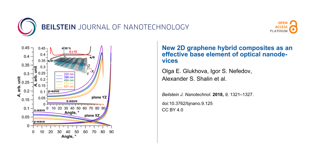
For wavelengths corresponding to the most intense peaks, a diagram of the dependence of absorption coefficient (Equation 8) on the angle of incidence was calculated for two cases: 1) the wave vector lies in the XZ-plane; 2) the wave vector lies in the YZ-plane. Figure 7 shows the change in the absorption coefficient for two types of polarized waves incident at different angles on the film of tubes (18,0) between the graphene sheets at a distance of 13 hexagons from each other. Diagrams for wavelengths of 250, 388, 454, 524 and 637 nm were calculated. These values were chosen in accordance with the calculated graphs, similar to Figure 5 and Figure 6. This choice was due to perspectives for using the investigated CNT–graphene hybrid nanocomposite film as a working part of optical antennas or polarizers. According to Figure 7 for all wavelengths the maximum absorption is observed for a p-wave at incidence angles of 85–87° for the irradiation in the YZ-plane, and at angles of 85–90° for the irradiation in the XZ-plane. The absorption reaches values of 45–50% at these angles of incidence. Thus, one can say that the optical properties of the composite do not explicitly depend on the type of the tubes.
![[2190-4286-9-125-7]](/bjnano/content/figures/2190-4286-9-125-7.png?scale=2.0&max-width=1024&background=FFFFFF)
Figure 7: Absorption coefficient of a 2D CNT–graphene hybrid nanocomposite (tube (18,0), 13 hexagons intertube distance) as a function of the angle of incidence at different wavelengths.
Figure 7: Absorption coefficient of a 2D CNT–graphene hybrid nanocomposite (tube (18,0), 13 hexagons intertub...
In summary, it can be concluded that the new 2D CNT–graphene hybrid nanocomposite is very promising for optoelectronic devices. In particular, the established regularities of change in absorbance as a function of the angle of incidence of the electromagnetic wave allows us to suggest the possibility of using the CNT–graphene film as a polarizer for electro-optical and magneto-optical thin film modulators. The advantages of such polarizers are a wide spectral range and low loss.
References
-
Mikhailov, S. A. Phys. Rev. B 2016, 93, 085403. doi:10.1103/PhysRevB.93.085403
Return to citation in text: [1] -
Cheng, J. L.; Vermeulen, N.; Sipe, J. E. New J. Phys. 2014, 16, 053014. doi:10.1088/1367-2630/16/5/053014
Return to citation in text: [1] -
Auditore, A.; De Angelis, C.; Locatelli, A.; Boscolo, S.; Midrio, M.; Romagnoli, M.; Capobianco, A.-D.; Nalesso, G. Opt. Lett. 2013, 38, 631–633. doi:10.1364/OL.38.000631
Return to citation in text: [1] -
Hendry, E.; Hale, P. J.; Moger, J.; Savchenko, A. K.; Mikhailov, S. A. Phys. Rev. Lett. 2010, 105, 097401. doi:10.1103/PhysRevLett.105.097401
Return to citation in text: [1] -
Maarouf, A. A.; Kasry, A.; Chandra, B.; Martyna, G. J. Carbon 2016, 102, 74–80. doi:10.1016/j.carbon.2016.02.024
Return to citation in text: [1] -
Gorkina, A. L.; Tsapenko, A. P.; Gilshteyn, E. P.; Koltsova, T. S.; Larionova, T. V.; Talyzin, A.; Anisimov, A. S.; Anoshkin, I. V.; Kauppinen, E. I.; Tolochko, O. V.; Nasibulin, A. G. Carbon 2016, 100, 501–507. doi:10.1016/j.carbon.2016.01.035
Return to citation in text: [1] -
Liu, Y.; Wang, F.; Wang, X.; Wang, X.; Flahaut, E.; Liu, X.; Li, Y.; Wang, X.; Xu, Y.; Shi, Y.; Zhang, R. Nat. Commun. 2015, 6, 8589. doi:10.1038/ncomms9589
Return to citation in text: [1] -
Gan, X.; Lv, R.; Bai, J.; Zhang, Z.; Wei, J.; Huang, Z. H.; Zhu, H.; Kang, F.; Terrones, M. 2D Mater. 2015, 2, 034003. doi:10.1088/2053-1583/2/3/034003
Return to citation in text: [1] -
Eckmann, A.; Felten, A.; Mishchenko, A.; Britnell, L.; Krupke, R.; Novoselov, K. S.; Casiraghi, C. Nano Lett. 2012, 12, 3925–3930. doi:10.1021/nl300901a
Return to citation in text: [1] -
Kholmanov, I. N.; Magnuson, C. W.; Piner, R.; Kim, J.-Y.; Aliev, A. E.; Tan, C.; Kim, T. Y.; Zakhidov, A. A.; Sberveglieri, G.; Baughman, R. H.; Ruoff, R. S. Adv. Mater. 2015, 27, 3053–3059. doi:10.1002/adma.201500785
Return to citation in text: [1] -
Tristán-López, F.; Morelos-Gómez, A.; Vega-Díaz, S. M.; García-Betancourt, M. L.; Perea-López, N.; Elías, A. L.; Muramatsu, H.; Cruz-Silva, R.; Tsuruoka, S.; Kim, Y. A.; Hayahsi, T.; Kaneko, K.; Endo, M.; Terrones, M. ACS Nano 2013, 7, 10788–10798. doi:10.1021/nn404022m
Return to citation in text: [1] [2] -
Elstner, M.; Porezag, D.; Jungnickel, G.; Elsner, J.; Haugk, M.; Frauenheim, T.; Suhai, S.; Seifert, G. Phys. Rev. B 1998, 58, 7260. doi:10.1103/PhysRevB.58.7260
Return to citation in text: [1] -
Elstner, M.; Seifert, G. Philos. Trans. R. Soc., A 2014, 372, 20120483. doi:10.1098/rsta.2012.0483
Return to citation in text: [1] -
Mitrofanov, V. V.; Slepchenkov, M. M.; Zhang, G.; Glukhova, O. E. Carbon 2017, 115, 803–810. doi:10.1016/j.carbon.2017.01.040
Return to citation in text: [1] [2] [3] [4] -
Landau, L. D.; Lifshitz, E. M.; Pitaevskii, L. P. Electrodynamics of Continuous Media, 2nd ed.; Pergamon: Oxford, United Kingdom, 1984.
Return to citation in text: [1] -
Marder, M. P. Condensed Matter Physics, 2nd ed.; Wiley-VCH: Berlin, Germany, 2011.
Return to citation in text: [1] -
Le, H. A.; Ho, S. T.; Chien, N. D.; Do, V. N. J. Phys.: Condens. Matter 2014, 26, 405304. doi:10.1088/0953-8984/26/40/405304
Return to citation in text: [1] -
Pedersen, T. G.; Pedersen, K.; Kriestensen, T. B. Phys. Rev. B 2001, 63, 201101(R). doi:10.1103/PhysRevB.63.201101
Return to citation in text: [1]
| 1. | Mikhailov, S. A. Phys. Rev. B 2016, 93, 085403. doi:10.1103/PhysRevB.93.085403 |
| 2. | Cheng, J. L.; Vermeulen, N.; Sipe, J. E. New J. Phys. 2014, 16, 053014. doi:10.1088/1367-2630/16/5/053014 |
| 3. | Auditore, A.; De Angelis, C.; Locatelli, A.; Boscolo, S.; Midrio, M.; Romagnoli, M.; Capobianco, A.-D.; Nalesso, G. Opt. Lett. 2013, 38, 631–633. doi:10.1364/OL.38.000631 |
| 4. | Hendry, E.; Hale, P. J.; Moger, J.; Savchenko, A. K.; Mikhailov, S. A. Phys. Rev. Lett. 2010, 105, 097401. doi:10.1103/PhysRevLett.105.097401 |
| 12. | Elstner, M.; Porezag, D.; Jungnickel, G.; Elsner, J.; Haugk, M.; Frauenheim, T.; Suhai, S.; Seifert, G. Phys. Rev. B 1998, 58, 7260. doi:10.1103/PhysRevB.58.7260 |
| 13. | Elstner, M.; Seifert, G. Philos. Trans. R. Soc., A 2014, 372, 20120483. doi:10.1098/rsta.2012.0483 |
| 10. | Kholmanov, I. N.; Magnuson, C. W.; Piner, R.; Kim, J.-Y.; Aliev, A. E.; Tan, C.; Kim, T. Y.; Zakhidov, A. A.; Sberveglieri, G.; Baughman, R. H.; Ruoff, R. S. Adv. Mater. 2015, 27, 3053–3059. doi:10.1002/adma.201500785 |
| 11. | Tristán-López, F.; Morelos-Gómez, A.; Vega-Díaz, S. M.; García-Betancourt, M. L.; Perea-López, N.; Elías, A. L.; Muramatsu, H.; Cruz-Silva, R.; Tsuruoka, S.; Kim, Y. A.; Hayahsi, T.; Kaneko, K.; Endo, M.; Terrones, M. ACS Nano 2013, 7, 10788–10798. doi:10.1021/nn404022m |
| 9. | Eckmann, A.; Felten, A.; Mishchenko, A.; Britnell, L.; Krupke, R.; Novoselov, K. S.; Casiraghi, C. Nano Lett. 2012, 12, 3925–3930. doi:10.1021/nl300901a |
| 14. | Mitrofanov, V. V.; Slepchenkov, M. M.; Zhang, G.; Glukhova, O. E. Carbon 2017, 115, 803–810. doi:10.1016/j.carbon.2017.01.040 |
| 5. | Maarouf, A. A.; Kasry, A.; Chandra, B.; Martyna, G. J. Carbon 2016, 102, 74–80. doi:10.1016/j.carbon.2016.02.024 |
| 6. | Gorkina, A. L.; Tsapenko, A. P.; Gilshteyn, E. P.; Koltsova, T. S.; Larionova, T. V.; Talyzin, A.; Anisimov, A. S.; Anoshkin, I. V.; Kauppinen, E. I.; Tolochko, O. V.; Nasibulin, A. G. Carbon 2016, 100, 501–507. doi:10.1016/j.carbon.2016.01.035 |
| 7. | Liu, Y.; Wang, F.; Wang, X.; Wang, X.; Flahaut, E.; Liu, X.; Li, Y.; Wang, X.; Xu, Y.; Shi, Y.; Zhang, R. Nat. Commun. 2015, 6, 8589. doi:10.1038/ncomms9589 |
| 8. | Gan, X.; Lv, R.; Bai, J.; Zhang, Z.; Wei, J.; Huang, Z. H.; Zhu, H.; Kang, F.; Terrones, M. 2D Mater. 2015, 2, 034003. doi:10.1088/2053-1583/2/3/034003 |
| 14. | Mitrofanov, V. V.; Slepchenkov, M. M.; Zhang, G.; Glukhova, O. E. Carbon 2017, 115, 803–810. doi:10.1016/j.carbon.2017.01.040 |
| 15. | Landau, L. D.; Lifshitz, E. M.; Pitaevskii, L. P. Electrodynamics of Continuous Media, 2nd ed.; Pergamon: Oxford, United Kingdom, 1984. |
| 17. | Le, H. A.; Ho, S. T.; Chien, N. D.; Do, V. N. J. Phys.: Condens. Matter 2014, 26, 405304. doi:10.1088/0953-8984/26/40/405304 |
| 14. | Mitrofanov, V. V.; Slepchenkov, M. M.; Zhang, G.; Glukhova, O. E. Carbon 2017, 115, 803–810. doi:10.1016/j.carbon.2017.01.040 |
| 18. | Pedersen, T. G.; Pedersen, K.; Kriestensen, T. B. Phys. Rev. B 2001, 63, 201101(R). doi:10.1103/PhysRevB.63.201101 |
| 11. | Tristán-López, F.; Morelos-Gómez, A.; Vega-Díaz, S. M.; García-Betancourt, M. L.; Perea-López, N.; Elías, A. L.; Muramatsu, H.; Cruz-Silva, R.; Tsuruoka, S.; Kim, Y. A.; Hayahsi, T.; Kaneko, K.; Endo, M.; Terrones, M. ACS Nano 2013, 7, 10788–10798. doi:10.1021/nn404022m |
| 14. | Mitrofanov, V. V.; Slepchenkov, M. M.; Zhang, G.; Glukhova, O. E. Carbon 2017, 115, 803–810. doi:10.1016/j.carbon.2017.01.040 |
| 16. | Marder, M. P. Condensed Matter Physics, 2nd ed.; Wiley-VCH: Berlin, Germany, 2011. |
© 2018 Glukhova et al.; licensee Beilstein-Institut.
This is an Open Access article under the terms of the Creative Commons Attribution License (http://creativecommons.org/licenses/by/4.0), which permits unrestricted use, distribution, and reproduction in any medium, provided the original work is properly cited.
The license is subject to the Beilstein Journal of Nanotechnology terms and conditions: (https://www.beilstein-journals.org/bjnano)