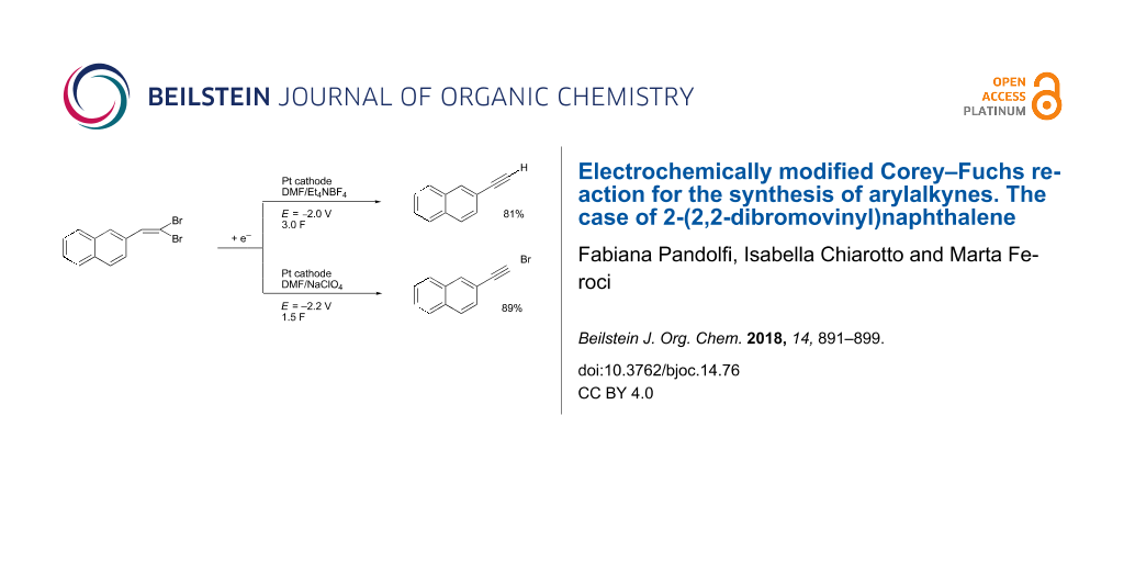
Abstract
The electrochemical reduction of 2-(2,2-dibromovinyl)naphthalene in a DMF solution (Pt cathode) yields selectively 2-ethynylnaphthalene or 2-(bromoethynyl)naphthalene in high yields, depending on the electrolysis conditions. In particular, by simply changing the working potential and the supporting electrolyte, the reaction can be directed towards the synthesis of the terminal alkyne (Et4NBF4) or the bromoalkyne (NaClO4). This study allowed to establish that 2-(bromoethynyl)naphthalene can be converted into 2-ethynylnaphthalene by cathodic reduction.

Graphical Abstract
Introduction
Terminal alkynes, due to the considerable triple-bond strength (839 kJ mol−1), are characterized by a moderate thermodynamic reactivity [1]. Nevertheless, both the C–C triple bond and the terminal C–H bond can be efficiently and selectively activated by metal or metal-free catalysts. Therefore, terminal alkynes can be considered as raw material (thus an important resource).
The use of terminal alkynes, activated by catalysts, as building blocks or intermediates in the synthesis of a large number of chemicals is extensively summarized in recent reviews [1-3]. The recently published papers confirm the present interest in the chemistry of terminal alkynes, e.g., in the synthesis of sulfinamides and isothiazoles [4], 1,3-enynes [5], α-monosubstituted propargylamines [6], 2-substituted pyrazolo[5,1-a]isoquinolines [7], etc.
Terminal alkynes can be prepared by dehydrohalogenation of vicinal dihalides or vinyl bromides using sodium in ammonia or strong bases [8]. Alternatively, the compounds are accessible by homologation of aldehydes following the Bestmann modification of the Seyferth–Gilbert reaction, using in situ generated dimethyl (diazomethyl)phosphonate [9,10]. Moreover, the aldehyde homologation to terminal alkynes can also be obtained using the Corey–Fuchs reaction [11]. This is a two-step reaction in which an aldehyde is at first converted into a 1,1-dibromoalkene with chain extension by one carbon atom through the reaction with carbon tetrabromide and triphenylphosphine (Scheme 1, reaction 1). The second step comprises the conversion of the 1,1-dibromoalkene into the corresponding alkyne by reaction with BuLi at −78 °C in THF (Scheme 1, reaction 2) [12].
![[1860-5397-14-76-i1]](/bjoc/content/inline/1860-5397-14-76-i1.svg?scale=2.0&max-width=1024&background=FFFFFF)
Recently, a chemical modification of the second step of the Corey–Fuchs reaction was reported, in which the authors used Cs2CO3 as the base and performed the reaction in DMSO at 115 °C for 12 h [13]. Good to high yields of terminal alkynes were obtained (50–98%). Also DBU (4 equiv) in MeCN at room temperature is effective to carry out the second step of the Corey–Fuchs reaction, affording good to high yields of arylalkynes. In the latter reaction DBU acts both as base and as organocatalyst [14]. In all cases, an excess of a strong base or high temperature are necessary for the reaction to proceed. An overview on the importance of the Corey–Fuchs reaction for the synthesis of natural products has been pointed out by Heravi and co-workers recently [15].
As mentioned above the second step of the Corey–Fuchs reaction requires the cleavage of a C–Br bond. We thus envisaged if this could be achieved electrochemically via a selective cathodic cleavage of the C–Br bond. In this way, the reaction could be performed under mild conditions and in the absence of reducing agents or bases in the reaction mixture.
Electrochemical methods can be considered an environmentally friendly technique: they rely on the use of practically massless electrons (which are not converted to byproducts) instead of stoichiometric amounts of redox reagents and frequently these reactions are carried out at room temperature and at atmospheric pressure, etc. [16-19].
The electrochemical behavior of halogenated compounds has been extensively investigated [20-22]. The cleavage of the C–halogen bond, yielding (via a radical intermediate) the corresponding carbanion and halogen anion, can be achieved by a bielectronic cathodic process (Scheme 2). The electrolysis is carried out at a suitable controlled potential, i.e., at a potential that is negative enough to achieve the selective fission of the envisaged C–halogen bond [23].
![[1860-5397-14-76-i2]](/bjoc/content/inline/1860-5397-14-76-i2.svg?scale=2.0&max-width=1024&background=FFFFFF)
Scheme 2: Electrochemical reduction of a carbon–halogen bond.
Scheme 2: Electrochemical reduction of a carbon–halogen bond.
Therefore, the reactive species is an electrochemically generated carbanion and the outcome of the reaction strongly depends on the complex reactivity of this intermediate. Moreover, this reactivity is influenced by the reaction conditions, such as the solvent, supporting electrolyte, electroinactive substrates, temperature, working potential and amount of consumed charge [24].
Our group intensively investigated the electrochemical behavior of 1,1-dibromoalkenes by means of cyclic voltammetry and electrolyses [25] and we reported the selective synthesis of vinyl bromides through the cathodic reduction of 1,1-dibromoalkenes in the presence of acetic acid. The electrolysis conditions in this transformation were optimized in order to avoid or minimize the formation of the terminal alkyne. The latter was obtained as the major product in the absence of a proton donor and its formation could be suppressed when performing the reaction with a Au cathode in acetonitrile (ACN) as the solvent and in the presence of an excess of acetic acid as the proton source. Under these conditions good yields of the vinyl bromides were obtained with preference of the Z-isomers (Scheme 3).
![[1860-5397-14-76-i3]](/bjoc/content/inline/1860-5397-14-76-i3.svg?scale=2.0&max-width=1024&background=FFFFFF)
Scheme 3: Electrochemical synthesis of vinyl bromides [25].
Scheme 3: Electrochemical synthesis of vinyl bromides [25].
We have now reconsidered this investigation in order to obtain terminal alkynes and to avoid the formation of vinyl bromides. The scope of this paper is the determination of the electrolysis conditions for the transformation of 1,1-dibromoalkenes into the corresponding terminal alkynes, in order to carry out the second step of the Corey–Fuchs reaction under milder conditions.
2-Ethynylnaphthalene (2a) is a small molecule with a high and selective biological activity. In particular, this molecule has been demonstrated to be a selective inactivator of cytochrome P-450 2B4 [26] and an inhibitor also of other cytochrome P-450 isoforms [27]. We thus decided to carry out our study using 2-(2,2-dibromovinyl)naphthalene (1a) as starting material for the synthesis of 2-ethynylnaphthalene (2a, Scheme 4).
![[1860-5397-14-76-i4]](/bjoc/content/inline/1860-5397-14-76-i4.svg?scale=2.0&max-width=1024&background=FFFFFF)
Results and Discussion
In our previous work [25], we found that the cathodic reduction of 2-(2,2-dibromovinyl)naphthalene (1a), carried out at the potential of the first voltammetric peak in ACN on a Au cathode and in the presence of an excess acetic acid, yielded the corresponding vinyl bromides (Scheme 3) in 75% yield (Z/E 82:18). The main product was 2-ethynylnaphthalene (2a, 65%) when the electrolysis was carried out in the absence of acetic acid as protonating agent (1.8 F consumed charge). Due to the importance of the latter product, we decided to reconsider this procedure in order to direct the synthesis towards the formation of the alkyne. We have therefore reconsidered the voltammetric behavior of 1a at Pt, Ag and GC cathodes in DMF or ACN solutions (Figure 1).
![[1860-5397-14-76-1]](/bjoc/content/figures/1860-5397-14-76-1.png?scale=2.0&max-width=1024&background=FFFFFF)
Figure 1: Voltammetric curves of 1a 0.020 mol dm−3; Pt, glassy carbon (GC) or Ag cathode. ν = 0.2 V s−1, T = 25 °C; solvent left: DMF/Et4NBF4 0.1 mol dm−3; right: ACN/Et4NBF4 0.1 mol dm−3.
Figure 1: Voltammetric curves of 1a 0.020 mol dm−3; Pt, glassy carbon (GC) or Ag cathode. ν = 0.2 V s−1, T = ...
The voltammetric curves of 1a show the presence of different reduction peaks which are affected by the solvent and by the electrode material (see peak potential Table S1 in Supporting Information File 1). These voltammograms (and the data reported in Supporting Information File 1, Table S1) evidence the catalytic effect of the silver cathode in the C–Br bond reduction (Ep1 is quite less negative on Ag cathode) [28,29], although this effect is more evident in DMF than in ACN. In any voltammogram, the cathodic peak at the less negative potential should be related to the cleavage of the C–Br bond. In order to confirm this statement, we carried out a first electrolysis in acetonitrile on a Pt cathode at the controlled potential of −1.75 V vs SCE, corresponding to the first reduction wave of 1a (Table 1, entry 1). The current flow was stopped after the disappearance of 1a (6.0 F). The only product was the expected alkyne 2a (Scheme 4) with 69% yield. This result was in accordance with what reported in our previous work using a Au cathode (but with a much lower current efficiency – probably due to side reactions – when compared to the result obtained using a Au cathode in the previous paper) [25].
Table 1: Electrochemical synthesis of 2-ethynylnaphthalene (2a). Electrolysis conditions optimization (Scheme 5).a
| entry | cathode | E or Ib | Fc | products (%)d | |||
|---|---|---|---|---|---|---|---|
| 2a | 3a | 4a | 5a | ||||
| 1e | Pt | −1.75 V | 6.0 | 69 | – | – | – |
| 2 | Pt | −2.00 V | 3.0 | 80 | – | traces | traces |
| 3 | Pt | −2.00 V | 4.0 | 81 | – | traces | – |
| 4 | Pt | −1.75 V | 1.5 | 25 | 48 | 4 | traces |
| 5f | Pt | −1.75 V | 2.3 | 27 | – | – | 58g |
| 6 | Pt | 10 mA/cm2 | 3.0 | 46 | – | 41 | – |
| 7 | Pt | 5 mA/cm2 | 3.0 | 29 | – | 39 | – |
| 8 | GC | −1.70 V | 0.6 | 5 | 7 | – | 7 |
| 9 | Ag | −1.80 V | 3.0 | 72 | – | 6 | – |
| 10 | Ag | −2.10 V | 3.0 | 65 | – | 15 | 2 |
| 11h | Pt | −2.20 V | 2.0 | 7 | 89 | – | – |
| 12h | Pt | −2.20 V | 3.0 | 43 | 38 | – | – |
aElectrolysis conditions: divided cell, 5.0 mL of DMF (catholyte)/0.1 mol dm−3 Et4NBF4 containing 1a (0.5 mmol), rt, N2 atmosphere. Anolyte: 2.0 mL same solvent. Working electrode: as in Table; anode: Pt; reference electrode: modified SCE (see Supporting Information File 1). The electrolyses were stopped after total consumption of starting 1a. bControlled potential electrolyses: working potential E (Volts) reported vs SCE. Controlled current electrolyses: working current density I (mA/cm2) reported. cAmount of charge: number of Faradays. dIsolated yields, with respect to starting 1a. eACN instead of DMF as solvent. f3 Equivalents of acetic acid were present in the catholyte during electrolysis. gMixture of isomers: Z/E = 69:31. hNaClO4 instead of Et4NBF4 as supporting electrolyte.
![[1860-5397-14-76-i5]](/bjoc/content/inline/1860-5397-14-76-i5.svg?scale=2.0&max-width=1024&background=FFFFFF)
Scheme 5: Possible products from the electrolysis of 2-(2,2-dibromovinyl)naphthalene (1a).
Scheme 5: Possible products from the electrolysis of 2-(2,2-dibromovinyl)naphthalene (1a).
In order to ascertain the role of the solvent in this electrosynthesis, we carried out an electrolysis in DMF instead of ACN on a Pt cathode at the controlled potential of −2.00 V vs SCE, corresponding to the first reduction wave of 1a (Table 1, entry 2). The current flow was stopped after the disappearance of 1a (3.0 F). Also in this case the only product was the expected alkyne 2a with a higher yield (80%).
An increase in the charge did not lead to an increase of the yield (81%, Table 1, entry 3). When the working potential was increased to −1.75 V and the electrolysis was stopped after the total consumption of 1a (1.5 F), a mixture of products was obtained (Scheme 5 and Table 1, entry 4). In particular, a large amount (48%) of the brominated alkyne 3a was isolated, along with traces of hydrogenated alkene 4a. In order to confirm the effect of the presence of a proton donor, acetic acid was added to the solution and the electrolysis was carried out at the first cathodic peak potential (Table 1, entry 5). After 2.3 F (total consumption of starting material), the alkyne 2a was isolated in 27% yield, while the major product was bromoalkene 5a (mixture of Z and E isomers) in 58% yield. This result is very similar to what we reported in our previous work [25].
Also the electrochemical methodology has a dramatic effect on the products of the cathodic reduction of 1a. In fact, carrying out the electrolysis under controlled current conditions (Table 1, entry 6) equimolar amounts of desired alkyne 2a and of vinyl derivative 4a (Scheme 5) were obtained when a current density of 10 mA/cm2 was used, while lowering the current density to 5 mA/cm2 did not alter significantly the reaction outcome (Table 1, entry 6 vs 7).
It is well known that the electrode material could influence the outcome of an electrosynthesis, so we carried out electrolyses of 1a using a glassy carbon cathode (Table 1, entry 8) and a silver cathode (Table 1, entry 9). In both cases the working potential was that of the first reduction wave. In the case of glassy carbon, the electrolysis could not be terminated as the current flow stopped very early [30]. When a silver cathode was used, a good yield of desired alkyne 2a was obtained (72%), along with a small amount of hydrogenated alkene 4a (6%). In order to increase the yield of alkyne 2a (and as 2a reduction potential is much more negative, vide infra), we carried out a cathodic reduction of 1a on a silver cathode at the second reduction wave potential (Table 1, entry 10). In this last case, the selectivity of the reaction dropped and a notable amount of hydrogenated alkene 4a was obtained (15%), along with a lower yield of alkyne 2a (65%).
The effect of a different supporting electrolyte was evaluated by substitution of Et4NBF4 with NaClO4. Also in this case the electrolysis was stopped after the complete consumption of starting 1a (Table 1, entry 11). The change in supporting electrolyte led to a complete change in products. In fact, a very high yield of 2-(bromoethynyl)naphthalene (3a) was obtained (89%), along with only 7% of 2-ethynylnaphthalene (2a) after 2.0 F. Increasing the consumed charge to 3.0 F under the same experimental conditions, an equimolar mixture of bromoalkyne 3a and alkyne 2a was obtained, confirming the possibility of obtaining 2a by cathodic reduction of 3a (Table 1, entry 11 vs 12).
In order to better understand the electrochemical behavior of dibromoalkene 1a, we carried out the voltammetric analysis of all isolated products (see Supporting Information File 1). The first cathodic peak potential of 2-(bromoethynyl)naphthalene (3a, Scheme 5) is very close to the first cathodic peak potential of 2-(2,2-dibromovinyl)naphthalene (1a), irrespective of the solvent and working electrode material. This renders impossible a selective cathodic reduction of 1a in the presence of 3a. The voltammetric behavior of 2-ethynylnaphthalene (2a) shows only one reduction peak at a potential that is quite more negative than the first cathodic peak of 1a and 3a, respectively, and corresponding to the third reduction peak of 1a and to the second of 3a. Also in this case the potential value is independent of the solvent and working electrode material. This voltammetric analysis shows that the cathodic reduction of both 1a and 3a could lead to the formation of the desired alkyne 2a.
To ascertain this hypothesis and to get information on the nature of the intermediates of the electrochemical process, we carried out the electrosynthesis under the optimized experimental conditions reported in Table 1, entry 2, analyzing the catholyte during the electrolysis. The yields of electrolysis products 2a and 3a were reported as a function of the number of Faraday (Figure 2).
![[1860-5397-14-76-2]](/bjoc/content/figures/1860-5397-14-76-2.png?scale=2.0&max-width=1024&background=FFFFFF)
Figure 2: Variation of the amounts of 1a, 2a, and 3a with the number of Faradays of 1a.
Figure 2: Variation of the amounts of 1a, 2a, and 3a with the number of Faradays of 1a.
The results of this last investigation (curves reported in Figure 2) show that i) the concentration of 1a decreases and that of 2a increases with increasing charge; ii) dibromoalkene 1a is completely reduced after a consumption of 2.0 F, i.e., a value of charge near the theoretical value for the bielectronic reduction of a C–Br bond; iii) after a consumption of 2.0 F the yield of alkyne 2a is 40% versus a yield of 80% after 3.0 F; iv) the analysis of the solution during the electrolysis shows the presence of bromoalkyne 3a.
The concentration of 3a initially increases and subsequently decreases upon increasing the charge; bromoalkyne 3a is absent in the final solution. The maximum yield of 3a, close to 50%, is reached after the consumption of about 1.5 F.
Bromoalkyne 3a and alkyne 2a seem to be strictly related. In fact, the increase of 3a corresponds to the decrease of starting 1a, while the subsequent decrease of 3a corresponds to the increase of 2a. In addition the analysis of the electrolyzed solutions shows the presence of only a trace amount of vinyl bromide 5a. Note that vinyl bromide 5a is cathodically active at the working potential (see Supporting Information File 1). The overall analysis allows suggesting a mechanistic hypothesis (Scheme 6).
![[1860-5397-14-76-i6]](/bjoc/content/inline/1860-5397-14-76-i6.svg?scale=2.0&max-width=1024&background=FFFFFF)
Scheme 6: Mechanistic hypothesis for the synthesis of alkyne 2a and bromoalkyne 3a from 2-(2,2-dibromovinyl)naphthalene (1a). Alkene configurations are not defined.
Scheme 6: Mechanistic hypothesis for the synthesis of alkyne 2a and bromoalkyne 3a from 2-(2,2-dibromovinyl)n...
The bielectronic cathodic reduction of dibromoalkene 1a leads to the cleavage of one C–Br bond and the formation of the corresponding vinyl anion (Scheme 6, reaction 1). An equilibrium of proton exchange between this electrogenerated carbanion and parent 1a yields vinylbromide 5a and a second vinyl anion (Scheme 2, reaction 2), which is converted to bromoalkyne 3a by bromide elimination. Vinyl bromide 5a can be cathodically reduced to 2-vinylnaphthalene (4a) or eliminate HBr to yield alkyne 2a.
Bromoalkyne 3a then can be reduced at the electrode to yield alkyne 2a. The presence of a proton donor (Table 1, entry 5) increases the yield of 5a and substitutes 1a (as proton donor) in reaction 2 (Scheme 6).
The anion generated by cathodic reduction of dibromoalkene 1a (Scheme 2, reaction 1) can also eliminate bromide (as reported in literature [31]), yielding the corresponding carbene (Scheme 2, reaction 2). This carbene can undergo a rearrangement to yield alkyne 2a. According to the mechanism shown in Scheme 6, the formation of bromoalkyne 3a competes with the formation of 2a in reaction 2 and its rate of formation is comparable to that of 2a. Since its reduction potential is close to that of 1a (see Supporting Information File 1, Table S1 and Figure S2), it is further reduced to the alkyne 2a (reaction 3 in Scheme 6) during the electrolysis.
The various possible ways described in Scheme 6 are highly influenced by the reaction conditions. When the supporting electrolyte is NaClO4 instead of Et4NBF4, a different mechanism seems to be operative. In fact, following reactions (1) and (2) in Scheme 6, a maximum yield of 50% of 3a can be obtained. It is thus possible that when using NaClO4 an electrogenerated base (OH−) is formed, due to the reduction of water and this base converts 1a to 3a. In fact, the Na+ cation is highly hydrophilic while the Et4N+ cation is hydrophobic. Thus, in DMF/NaClO4 the double layer would be constituted by the strongly solvated Na+(H2O)n, while in DMF/Et4NBF4, the double layer would be free of water. On Pt, a low hydrogen overvoltage material, it is then conceivable that the reduction of water to dihydrogen and hydroxide anions would be faster than the reduction of 1a. The overall reaction would be a one-electron process catalyzed by water reduction (Scheme 7) [32].
![[1860-5397-14-76-i7]](/bjoc/content/inline/1860-5397-14-76-i7.svg?scale=2.0&max-width=1024&background=FFFFFF)
Scheme 7: Possible reaction using NaClO4 as supporting electrolyte.
Scheme 7: Possible reaction using NaClO4 as supporting electrolyte.
It is thus possible by selecting the electrolysis conditions to synthesize selectively 2-ethynylnaphthalene (2a, Table 1, entry 2) or 2-(bromoethynyl)naphthalene (3a, Table 1, entry 11) in high yields.
Finally, to test the general applicability of the proposed electrochemical methodology, we submitted to electrolysis (under the optimized conditions reported in Table 1, entry 2), 3-(2,2-dibromovinyl)-9-ethyl-9H-carbazole (1b, Scheme 8). In fact, the corresponding alkyne 2b is an important intermediate in the synthesis of molecules for organic electronics (e.g., organic light-emitting diodes [33] and organic field-effect transistors [34]). The voltammetric analysis showed a behavior similar to that of 1a (see Supporting Information File 1) and thus the electrolysis was carried out at the second wave potential. 9-Ethyl-3-ethynyl-9H-carbazole (2b) was obtained in 77% yield.
![[1860-5397-14-76-i8]](/bjoc/content/inline/1860-5397-14-76-i8.svg?scale=2.0&max-width=1024&background=FFFFFF)
Scheme 8: Electrochemical synthesis of 9-ethyl-3-ethynyl-9H-carbazole (2b).
Scheme 8: Electrochemical synthesis of 9-ethyl-3-ethynyl-9H-carbazole (2b).
Similarly, when starting from 1-(2,2-dibromovinyl)-4-methoxybenzene (1c), the corresponding terminal alkyne 2c was obtained in 62% yield (Scheme 9).
![[1860-5397-14-76-i9]](/bjoc/content/inline/1860-5397-14-76-i9.svg?scale=2.0&max-width=1024&background=FFFFFF)
Scheme 9: Electrochemical synthesis of 1-ethynyl-4-methoxybenzene (2c).
Scheme 9: Electrochemical synthesis of 1-ethynyl-4-methoxybenzene (2c).
Conclusion
The electrochemical methodology is shown to be a useful tool in organic synthesis. The possibility to direct the reaction towards different products simply by changing the electrolysis parameters (potential, solvent, supporting electrolyte, amount of charge, additives, etc.) and making use of electrons (as green, cheap, no byproduct-forming reagents) renders electrosynthesis attractive for organic chemists.
In particular, this work reported the selective synthesis of 2-ethynylnaphthalene or 2-(bromoethynyl)naphthalene in high yields by the cathodic reduction of 2-(2,2-dibromovinyl)naphthalene. The electrolyses were carried out in DMF solution (Pt cathode) under potentiostatic conditions; if the potential was fixed at −2.00 V (vs SCE) and the supporting electrolyte was Et4NBF4, and 2-ethynylnaphthalene was obtained in 80% yield after 3.0 F, while using NaClO4 as salt and a potential of −2.20 V 2-(bromoethynyl)naphthalene was obtained in 89% yield after 2.0 F. We also demonstrated that 2-(bromoethynyl)naphthalene can be cathodically converted to 2-ethynylnaphthalene. The extension of the method to two other substrates was successfully demonstrated. This methodology allows carrying out the second step of the Corey–Fuchs reaction under milder experimental conditions.
Experimental
Electrolyses. Constant potential or current electrolyses were performed under a nitrogen atmosphere at 25 °C using an Amel 2053 potentiostat-galvanostat equipped with an Amel 731 integrator. All experiments were carried out in a divided glass cell separated through a porous glass plug filled with a layer of gel (i.e., methyl cellulose 0.5 vol % dissolved in DMF/Et4NBF4, 1.0 mol dm−3). Pt spirals (apparent area 0.8 cm2) were used as both cathode and anode, unless otherwise specified. Catholyte: 5 mL of DMF/0.1 M Et4NBF4; anolyte: 2 mL of the same solvent of catholyte. 2,2-Dibromovinylnaphthalene (0.5 mmol) was present in the catholyte during electrolysis. The number of Coulombs and the electrolysis potential/current were varied as reported in the text. At the end of the electrolysis, the catholyte was poured in an excess of water and extracted with petroleum ether 40–60 (3 × 20 mL). Flash column chromatography (eluent: petroleum ether/ethyl acetate from 100:0 to 90:10) gave purified products.
Supporting Information
| Supporting Information File 1: Detailed experimental procedures, NMR spectra and cyclic voltammetries. | ||
| Format: PDF | Size: 1.5 MB | Download |
References
-
Lei, J.; Su, L.; Zeng, K.; Chen, T.; Qiu, R.; Zhou, Y.; Au, C.-T.; Yin, S.-F. Chem. Eng. Sci. 2017, 171, 404–425. doi:10.1016/j.ces.2017.05.021
Return to citation in text: [1] [2] -
Chinchilla, R.; Nájera, C. Chem. Rev. 2014, 114, 1783–1826. doi:10.1021/cr400133p
Return to citation in text: [1] -
Ackermann, L. Acc. Chem. Res. 2014, 47, 281–295. doi:10.1021/ar3002798
Return to citation in text: [1] -
Rodríguez, M. R.; Beltrán, Á.; Mudarra, Á. L.; Álvarez, E.; Maseras, F.; Díaz-Requejo, M. M.; Pérez, P. J. Angew. Chem., Int. Ed. 2017, 56, 12842–12847. doi:10.1002/anie.201705664
Return to citation in text: [1] -
Islas, R. E.; Cárdenas, J.; Gaviño, R.; García-Ríos, E.; Lomas-Romero, L.; Morales-Serna, J. A. RSC Adv. 2017, 7, 9780–9789. doi:10.1039/c6ra28855c
Return to citation in text: [1] -
Takano, S.; Kochi, T.; Kakiuchi, F. Chem. Lett. 2017, 46, 1620–1623. doi:10.1246/cl.170754
Return to citation in text: [1] -
Liu, H.; Lu, L.; Hua, R. Tetrahedron 2017, 73, 6428–6435. doi:10.1016/j.tet.2017.09.037
Return to citation in text: [1] -
Campbell, K. N.; Campbell, B. K. Org. Synth.; Coll. Vol. 4; 1963; pp 763–766.
Return to citation in text: [1] -
Müller, S. G.; Liepold, B.; Roth, G. J.; Bestmann, H. J. Synlett 1996, 521–522. doi:10.1055/s-1996-5474
Return to citation in text: [1] -
Roth, G. J.; Liepold, B.; Müller, S. G.; Bestmann, H. J. Synthesis 2004, 59–62. doi:10.1055/s-2003-44346
Return to citation in text: [1] -
Corey, E. J.; Fuchs, P. L. Tetrahedron Lett. 1972, 13, 3769–3772. doi:10.1016/S0040-4039(01)94157-7
Return to citation in text: [1] -
Sahu, B.; Muruganantham, R.; Namboothiri, I. N. N. Eur. J. Org. Chem. 2007, 2477–2489. doi:10.1002/ejoc.200601137
Return to citation in text: [1] -
Zhao, M.; Kuang, C.; Yang, Q.; Cheng, X. Tetrahedron Lett. 2011, 52, 992–994. doi:10.1016/j.tetlet.2010.12.071
Return to citation in text: [1] -
Morri, A. K.; Thummala, Y.; Doddi, V. R. Org. Lett. 2015, 17, 4640–4643. doi:10.1021/acs.orglett.5b02398
Return to citation in text: [1] -
Heravi, M. M.; Asadi, S.; Nazari, N.; Lashkariani, M. B. Curr. Org. Chem. 2015, 19, 2196–2219. doi:10.2174/1385272819666150619174010
Return to citation in text: [1] -
Steckhan, E.; Arns, T.; Heineman, W. R.; Hilt, G.; Hoormann, D.; Jörissen, J.; Kröner, L.; Lewall, B.; Pütter, H. Chemosphere 2001, 43, 63–73. doi:10.1016/S0045-6535(00)00325-8
Return to citation in text: [1] -
Frontana-Uribe, B. A.; Little, R. D.; Ibanez, J. G.; Palma, A.; Vasquez-Medrano, R. Green Chem. 2010, 12, 2099–2119. doi:10.1039/C0GC00382D
Return to citation in text: [1] -
Schäfer, H. J. C. R. Chim. 2011, 14, 745–765. doi:10.1016/j.crci.2011.01.002
Return to citation in text: [1] -
Horn, E. J.; Rosen, B. R.; Baran, P. S. ACS Cent. Sci. 2016, 2, 302–308. doi:10.1021/acscentsci.6b00091
Return to citation in text: [1] -
Casanova, J.; Reddy, V. P. Electrochemistry of the carbon−halogen bond. In The Chemistry of Functional Groups, Supplement D2; Patai, S.; Rappoport, Z., Eds.; Wiley: New York, 1995; pp 1003–1067.
Return to citation in text: [1] -
Peters, D. G. Oxidation and reduction of halogen-containing compounds. In Encyclopedia of Electrochemistry; Schäfer, H. J., Ed.; Wiley-VCH Verlag GmbH: Weinheim, Germany, 2004; Vol. 8, pp 217–233.
Return to citation in text: [1] -
Torii, S. Electroreduction of Halogenated Compounds. Electroorganic Reduction Synthesis; Wiley-VCH Verlag GmbH: Weinheim, Germany, 2006; Vol. 1, pp 331–432.
Return to citation in text: [1] -
Peters, D. G. In Organic Electrochemistry, 5th ed.; Hammerich, O.; Speiser, B., Eds.; Taylor & Francis, LLC: London, 2016; pp 941–980.
Return to citation in text: [1] -
Martin, E. T.; McGuire, C. M.; Mubarak, M. S.; Peters, D. G. Chem. Rev. 2016, 116, 15198–15234. doi:10.1021/acs.chemrev.6b00531
Return to citation in text: [1] -
Feroci, M.; Orsini, M.; Palombi, L.; Sotgiu, G.; Inesi, A. Electrochim. Acta 2004, 49, 635–640. doi:10.1016/j.electacta.2003.09.018
Return to citation in text: [1] [2] [3] [4] [5] -
Strobel, S. M.; Szklark, G. D.; He, Y. Q.; Foroozesh, M.; Alworth, W. L.; Roberts, E. S.; Hollenberg, P. F.; Halpert, J. R. J. Pharmacol. Exp. Ther. 1999, 290, 445–451.
Return to citation in text: [1] -
Beebe, L. E.; Roberts, E. S.; Fornwald, L. W.; Hollenberg, P. F.; Alworth, W. L. Biochem. Pharmacol. 1996, 52, 1507–1513. doi:10.1016/S0006-2952(96)00525-4
Return to citation in text: [1] -
Mubarak, M. S.; Peters, D. G. Curr. Opin. Electrochem. 2017, 2, 60–66. doi:10.1016/j.coelec.2017.03.001
Return to citation in text: [1] -
Gennaro, A.; Isse, A. A.; Mussini, P. R. In Organic Electrochemistry, 5th ed.; Hammerich, O.; Speiser, B., Eds.; Taylor & Francis, LLC: London, 2016; pp 917–940.
Return to citation in text: [1] -
The use of glassy carbon (GC) as cathode was not possible probably due to adsorption of material on the electrode surface, which led to electrical insulation.
Return to citation in text: [1] -
Abbas, S.; Hayes, C. J.; Worden, S. Tetrahedron Lett. 2000, 41, 3215–3219. doi:10.1016/S0040-4039(00)00353-1
Return to citation in text: [1] -
We are grateful to a referee for suggesting this mechanistic hypothesis.
Return to citation in text: [1] -
Li, Y.-P.; Fan, X.-X.; Wu, Y.; Zeng, X.-C.; Wang, J.-Y.; Wei, Q.-H.; Chen, Z.-N. J. Mater. Chem. C 2017, 5, 3072–3078. doi:10.1039/c7tc00382j
Return to citation in text: [1] -
Kato, S.-i.; Noguchi, H.; Kobayashi, A.; Yoshihara, T.; Tobita, S.; Nakamura, Y. J. Org. Chem. 2012, 77, 9120–9133. doi:10.1021/jo3016538
Return to citation in text: [1]
| 33. | Li, Y.-P.; Fan, X.-X.; Wu, Y.; Zeng, X.-C.; Wang, J.-Y.; Wei, Q.-H.; Chen, Z.-N. J. Mater. Chem. C 2017, 5, 3072–3078. doi:10.1039/c7tc00382j |
| 34. | Kato, S.-i.; Noguchi, H.; Kobayashi, A.; Yoshihara, T.; Tobita, S.; Nakamura, Y. J. Org. Chem. 2012, 77, 9120–9133. doi:10.1021/jo3016538 |
| 1. | Lei, J.; Su, L.; Zeng, K.; Chen, T.; Qiu, R.; Zhou, Y.; Au, C.-T.; Yin, S.-F. Chem. Eng. Sci. 2017, 171, 404–425. doi:10.1016/j.ces.2017.05.021 |
| 6. | Takano, S.; Kochi, T.; Kakiuchi, F. Chem. Lett. 2017, 46, 1620–1623. doi:10.1246/cl.170754 |
| 20. | Casanova, J.; Reddy, V. P. Electrochemistry of the carbon−halogen bond. In The Chemistry of Functional Groups, Supplement D2; Patai, S.; Rappoport, Z., Eds.; Wiley: New York, 1995; pp 1003–1067. |
| 21. | Peters, D. G. Oxidation and reduction of halogen-containing compounds. In Encyclopedia of Electrochemistry; Schäfer, H. J., Ed.; Wiley-VCH Verlag GmbH: Weinheim, Germany, 2004; Vol. 8, pp 217–233. |
| 22. | Torii, S. Electroreduction of Halogenated Compounds. Electroorganic Reduction Synthesis; Wiley-VCH Verlag GmbH: Weinheim, Germany, 2006; Vol. 1, pp 331–432. |
| 5. | Islas, R. E.; Cárdenas, J.; Gaviño, R.; García-Ríos, E.; Lomas-Romero, L.; Morales-Serna, J. A. RSC Adv. 2017, 7, 9780–9789. doi:10.1039/c6ra28855c |
| 23. | Peters, D. G. In Organic Electrochemistry, 5th ed.; Hammerich, O.; Speiser, B., Eds.; Taylor & Francis, LLC: London, 2016; pp 941–980. |
| 4. | Rodríguez, M. R.; Beltrán, Á.; Mudarra, Á. L.; Álvarez, E.; Maseras, F.; Díaz-Requejo, M. M.; Pérez, P. J. Angew. Chem., Int. Ed. 2017, 56, 12842–12847. doi:10.1002/anie.201705664 |
| 15. | Heravi, M. M.; Asadi, S.; Nazari, N.; Lashkariani, M. B. Curr. Org. Chem. 2015, 19, 2196–2219. doi:10.2174/1385272819666150619174010 |
| 1. | Lei, J.; Su, L.; Zeng, K.; Chen, T.; Qiu, R.; Zhou, Y.; Au, C.-T.; Yin, S.-F. Chem. Eng. Sci. 2017, 171, 404–425. doi:10.1016/j.ces.2017.05.021 |
| 2. | Chinchilla, R.; Nájera, C. Chem. Rev. 2014, 114, 1783–1826. doi:10.1021/cr400133p |
| 3. | Ackermann, L. Acc. Chem. Res. 2014, 47, 281–295. doi:10.1021/ar3002798 |
| 16. | Steckhan, E.; Arns, T.; Heineman, W. R.; Hilt, G.; Hoormann, D.; Jörissen, J.; Kröner, L.; Lewall, B.; Pütter, H. Chemosphere 2001, 43, 63–73. doi:10.1016/S0045-6535(00)00325-8 |
| 17. | Frontana-Uribe, B. A.; Little, R. D.; Ibanez, J. G.; Palma, A.; Vasquez-Medrano, R. Green Chem. 2010, 12, 2099–2119. doi:10.1039/C0GC00382D |
| 18. | Schäfer, H. J. C. R. Chim. 2011, 14, 745–765. doi:10.1016/j.crci.2011.01.002 |
| 19. | Horn, E. J.; Rosen, B. R.; Baran, P. S. ACS Cent. Sci. 2016, 2, 302–308. doi:10.1021/acscentsci.6b00091 |
| 11. | Corey, E. J.; Fuchs, P. L. Tetrahedron Lett. 1972, 13, 3769–3772. doi:10.1016/S0040-4039(01)94157-7 |
| 13. | Zhao, M.; Kuang, C.; Yang, Q.; Cheng, X. Tetrahedron Lett. 2011, 52, 992–994. doi:10.1016/j.tetlet.2010.12.071 |
| 9. | Müller, S. G.; Liepold, B.; Roth, G. J.; Bestmann, H. J. Synlett 1996, 521–522. doi:10.1055/s-1996-5474 |
| 10. | Roth, G. J.; Liepold, B.; Müller, S. G.; Bestmann, H. J. Synthesis 2004, 59–62. doi:10.1055/s-2003-44346 |
| 14. | Morri, A. K.; Thummala, Y.; Doddi, V. R. Org. Lett. 2015, 17, 4640–4643. doi:10.1021/acs.orglett.5b02398 |
| 7. | Liu, H.; Lu, L.; Hua, R. Tetrahedron 2017, 73, 6428–6435. doi:10.1016/j.tet.2017.09.037 |
| 12. | Sahu, B.; Muruganantham, R.; Namboothiri, I. N. N. Eur. J. Org. Chem. 2007, 2477–2489. doi:10.1002/ejoc.200601137 |
| 25. | Feroci, M.; Orsini, M.; Palombi, L.; Sotgiu, G.; Inesi, A. Electrochim. Acta 2004, 49, 635–640. doi:10.1016/j.electacta.2003.09.018 |
| 24. | Martin, E. T.; McGuire, C. M.; Mubarak, M. S.; Peters, D. G. Chem. Rev. 2016, 116, 15198–15234. doi:10.1021/acs.chemrev.6b00531 |
| 25. | Feroci, M.; Orsini, M.; Palombi, L.; Sotgiu, G.; Inesi, A. Electrochim. Acta 2004, 49, 635–640. doi:10.1016/j.electacta.2003.09.018 |
| 30. | The use of glassy carbon (GC) as cathode was not possible probably due to adsorption of material on the electrode surface, which led to electrical insulation. |
| 31. | Abbas, S.; Hayes, C. J.; Worden, S. Tetrahedron Lett. 2000, 41, 3215–3219. doi:10.1016/S0040-4039(00)00353-1 |
| 25. | Feroci, M.; Orsini, M.; Palombi, L.; Sotgiu, G.; Inesi, A. Electrochim. Acta 2004, 49, 635–640. doi:10.1016/j.electacta.2003.09.018 |
| 25. | Feroci, M.; Orsini, M.; Palombi, L.; Sotgiu, G.; Inesi, A. Electrochim. Acta 2004, 49, 635–640. doi:10.1016/j.electacta.2003.09.018 |
| 25. | Feroci, M.; Orsini, M.; Palombi, L.; Sotgiu, G.; Inesi, A. Electrochim. Acta 2004, 49, 635–640. doi:10.1016/j.electacta.2003.09.018 |
| 28. | Mubarak, M. S.; Peters, D. G. Curr. Opin. Electrochem. 2017, 2, 60–66. doi:10.1016/j.coelec.2017.03.001 |
| 29. | Gennaro, A.; Isse, A. A.; Mussini, P. R. In Organic Electrochemistry, 5th ed.; Hammerich, O.; Speiser, B., Eds.; Taylor & Francis, LLC: London, 2016; pp 917–940. |
| 26. | Strobel, S. M.; Szklark, G. D.; He, Y. Q.; Foroozesh, M.; Alworth, W. L.; Roberts, E. S.; Hollenberg, P. F.; Halpert, J. R. J. Pharmacol. Exp. Ther. 1999, 290, 445–451. |
| 27. | Beebe, L. E.; Roberts, E. S.; Fornwald, L. W.; Hollenberg, P. F.; Alworth, W. L. Biochem. Pharmacol. 1996, 52, 1507–1513. doi:10.1016/S0006-2952(96)00525-4 |
© 2018 Pandolfi et al.; licensee Beilstein-Institut.
This is an Open Access article under the terms of the Creative Commons Attribution License (http://creativecommons.org/licenses/by/4.0), which permits unrestricted use, distribution, and reproduction in any medium, provided the original work is properly cited.
The license is subject to the Beilstein Journal of Organic Chemistry terms and conditions: (https://www.beilstein-journals.org/bjoc)