Abstract
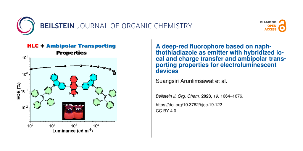
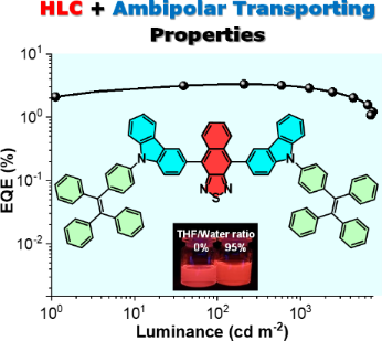
Herein, we report the synthesis and characterization of an efficient ambipolar charge-carrier-transporting deep-red fluorophore (TPECNz) based on a donor–acceptor–donor (D–A–D)-type molecule and its application as a non-doped emitter in an organic light-emitting diode (OLED). The fluorophore TPECNz contains naphtho[2,3-c][1,2,5]thiadiazole (Nz) as a strong acceptor unit symmetrically functionalized with N-(4-(1,2,2-triphenylvinyl)phenyl)carbazole as a donor and aggregation-induced emission (AIE) luminogen. The experimental (solvatochromic and emission in THF/water mixtures studies) and theoretical investigations prove that TPECNz retains cooperative hybridized local and charge transfer (HLCT) and weak AIE features. Thanks to its D–A–D-type structure with a proper twist angle between the D and A units, a strong electron deficiency of the Nz unit, and electron-donating and hole-transporting natures of carbazole, TPECNz exhibits a strong deep red emission (λem = 648 nm) with a high fluorescence quantum yield of 96%, outstanding thermal property (Tg = 236 °C), and ambipolar charge-carrier-transporting property with a decent balance of mobility of electrons (1.50 × 10⁻⁵ cm2 V−1 s−1) and holes (4.42 × 10⁻⁶ cm2 V−1 s−1). TPECNz is successfully employed as a non-doped emitter in an OLED which displays deep red electroluminescent emission peaked at 659 nm with CIE coordinates of (0.664, 0.335)), an EQEmax of 3.32% and exciton utilization efficiency (EUE) of 47%.
Graphical Abstract
Introduction
Recently, organic fluorophores with efficient deep-red/near-infrared (DR/NIR) emission properties (λem = 650–900 nm) have received much attention due to their potential applications in several different fields such as chemosensing [1-3], bioimaging/biosensing [4-8], photodynamic therapy [9], optical communication [10], NLO materials [11], laser dyes [12], and DR/NIR electroluminescent devices [13-18]. However, DR/NIR chromophores typically suffer from low photoluminescent quantum yields (PLQY) because of their intrinsic small band-gap energy causing larger vibronic coupling between the ground and excited states, particularly when they are applied as emitters in organic light-emitting diodes (OLEDs) [19]. Therefore, with such a constrained number of efficient emitters, the current advance of DR/NIR OLEDs largely trails behind the visible light emission OLEDs [20,21]. So far, remarkable efforts have been made in designing new DR/NIR organic fluorophores in combination with device engineering to build up the performance of DR/NIR OLEDs. In general, to realize high fluorescence in the DR/NIR region from the organic fluorophores, the challenges of their pronounced non-radiative processes, and high planarity and extended π-conjugation lengths which eventually favor the undesired formation of poorly emissive molecular aggregates must be overcome. Alternatively, donor–acceptor (D–A)-type organic fluorophores have been introduced and successfully exploited for the development of fluorophores with DR/NIR emissions without lengthy extension of their π-conjugation systems due to a broadening of both the valence and the conduction bands and a consequent narrowing of the energy gap [22-25]. The D–A characters also offer a tunability of optoelectronic properties such as energy levels, optical bandgap (Eg), and charge-transport properties, which could be done by selecting different D and A moieties [22,26-28]. In these fluorophores, the emission generally derives from intramolecular charge-transfer (CT) states at lower energy. Nonetheless, the formed CT state between D and A in such materials normally caused a lesser ΦPL because of the separated frontier molecular orbitals [29,30]. Recently, the reports by Ma et al. revealed that by designing suitable twist-angles between D and A and D–A strength, frontier molecular orbitals of D–A fluorophores are not completely separated due to overlap between the transition orbitals [31-33]. In these molecules, the lowest excited state still shows moderate or large oscillator strengths or a mixing of two excited-state components, locally excited (LE) state and CT excited state. This kind of excited state was later known as a hybridized local and charge transfer (HLCT) state, in which the CT component can provide a high-lying reversed intersystem crossing (hRISC) pathway for fast and effective triplet utilization in the device, and the LE component can contribute good PLQY [34-36]. So far, based on this concept, several D–A-type fluorophores have been designed and investigated including some DR/NIR materials [37-41]. Inevitably, these materials displayed high PLQY and exceptional OLED device performance [42-45]. Even though the radiative transition rate is improved for the HLCT fluorophores, the non-radiative transition process is still an obstacle to lowering the PLQY, particularly for the DR/NIR emitters [20,46]. Therefore, to enhance the performance of HLCT-based DR/NIR fluorophores the non-radiative transition process of the exited state needs to be resolved. This could be managed by the molecular design of the D–A structure. It has been reported that the performance of HLCT fluorophores greatly depends on the strength of donors, acceptors, and π spacers and the building blocks of HLCT should be carefully selected to regulate appropriate electron push–pull strength [32,35,47,48].
Here, a novel chromophore, 4,9-bis(9-(4-(1,2,2-triphenylvinyl)phenyl)-9H-carbazol-3-yl)naphtho[2,3-c][1,2,5]thiadiazole (TPECNz), built on a D–A–D type structure was designed and synthesized (Scheme 1). The D–A–D configuration was constructed by incorporating a second symmetrical donor in the D–A framework, which could further reduce the energy gap between HOMO/LUMO hybrid orbits and drive fluorescence emission to longer wavelengths [48,49]. In this molecular design, the strong electron-deficient naphtho[2,3-c][1,2,5]thiadiazole (Nz) [13,50,51] as an acceptor and the strong electron-donating carbazole [52] as a donor unit were used in the D–A–D structure to further reduce the bandgap, thereby red-shifting the absorption and emission wavelengths. In addition, the strong electron affinity of Nz and the electron-donating and hole-transporting ability of carbazole would build in the good ability to transport electrons and holes, respectively, providing well-balanced ambipolar characteristics. On the other hand, the attached 4-(1,2,2-triphenylvinyl)phenyl (TPE) moiety would induce aggregation-induced emission (AIE) as feature into the molecule. It was suspected that AIE would restrain the aggregation-caused quench (ACQ) and the energy loss through the vibronic coupling natures of the DR/NIR fluorophores [53]. As a result, TPECNz effectively possesses a strong deep-red emission with combined HLCT, weak AIE, and ambipolar transporting properties, which enabled its application as non-doped emitter. The TPECNz-based non-doped deep-red OLED realized a maximum external quantum efficiency (EQEmax) of 3.32% with an emission peak at 659 nm.
![[1860-5397-19-122-i1]](/bjoc/content/inline/1860-5397-19-122-i1.svg?scale=2.0&max-width=1024&background=FFFFFF)
Scheme 1: Synthesis of D–A–D chromophore TPECNz.
Scheme 1: Synthesis of D–A–D chromophore TPECNz.
Results and Discussion
The designed TPECNz molecule was synthesized by a multistep reaction as described in Scheme 1. Initially, an Ullmann coupling reaction of bromo-TPE 1 and carbazole provided TPE-N-carbazole 2 in good yield (87%). Compound 2 was then converted to the boronic ester intermediate 3 in 41% yield over two steps: monobromination at the carbazole unit of 2 with NBS/THF at low temperature giving the unisolated mixed brominated product followed by borylation with bis(pinacolato)diboron catalyzed by Pd(dpf)Cl2/KOAc. Finally, TPECNz was obtained as red solid in a reasonable yield by a Suzuki-type cross-coupling reaction between 3 and 4,9-dibromonaphtho[2,3-c][1,2,5]thiadiazole. The chemical structure and purity of compound 3 were verified by 1H NMR, 13C NMR, and high-resolution MALDI-TOF-MS techniques.
To examine the electronic properties of D–A TPECNz, density functional theory (DFT) calculations at the B3LYP level of theory with the 6-31G(d,p) basis set were performed. It has been previously reported that the twist angle of the D–A segment has a significant role in controlling the CT component in the HLCT state [54]. A suitable twisted angle (40–80°) allocated an appropriate tuning between the complete π‐conjugation and the pure CT transition character to form the HLCT state. As depicted in Figure 1a, the optimized structure of TPECNz revealed a twisted molecular configuration with dihedral angles of 54–56° between the planes of the terminal carbazole donors and the Nz acceptor that are beneficial for the state mixing between the LE and CT states. The lowest unoccupied molecular orbital (LUMO) was mainly localized on the Nz ring, while the highest occupied molecular orbital (HOMO) was delocalized over the Nz core and the attached carbazole moieties. There was an overlap between the HOMO and LUMO orbitals over the Nz fragment, which is likely to promote the LE component and consequently gives rise to a faster radiative decay and thus a higher luminescence efficiency. To further figure out excited-state properties of TPECNz, the natural transition orbitals (NTOs) of singlet (S) and triplet (T) excited states were executed based on time-dependent (TD)-DFT calculations at the CAM-B3LYP/6-31G(d) level of theory. As shown in Figure 1b, the hole and particle of TPECNz are similar to its HOMO and LUMO orbitals, respectively. The S0 → S1 transition with oscillator strength (ƒ) of 0.476 clearly showed HLCT transition characteristics, in which a certain overlap between hole and particle wavefunctions on the Nz ring represented for LE component inducing a high luminescence efficiency, while a significant spatial separation between hole and particle wavefunctions considered for CT component promoting RISC process along high-lying excitation state for enhancing an exciton utilization efficiency (EUE).
![[1860-5397-19-122-1]](/bjoc/content/figures/1860-5397-19-122-1.png?scale=2.0&max-width=1024&background=FFFFFF)
Figure 1: a) The optimized structure and HOMO/LUMO distributions calculated by B3LYP/6-31G(d,p) method. b) The natural transition orbits (NTOs) of the S0 → S1 transition computed by CAM-B3LYP/6-31G(d) method. The percentage is the proportion of transition and ƒ is the oscillator strength.
Figure 1: a) The optimized structure and HOMO/LUMO distributions calculated by B3LYP/6-31G(d,p) method. b) Th...
The photophysical properties of TPECNz were studied in solution, thin film, and solid powder. As shown in Figure 2a, the UV–vis absorption spectrum in diluted toluene solution displays intense absorption peaks in the high energy region (<380 nm) and a much weaker absorption peak at 508 nm attributed to the π–π* transition of the conjugated aromatic backbone and intramolecular charge-transfer (ICT) transition from carbazole donor to Nz acceptor, respectively. Such weak ICT absorption peak (ε = 17,000 M−1 cm−1) as compared to the π–π* absorption peak (ε = 95,300 M−1 cm−1) symbolizes a weak electronic coupling between the carbazole donor and the Nz acceptor parts because of the twisted configuration between them as observed in the optimized structure (Figure 1a) [47]. In solution, TPECNz exhibits a strong deep-red emission with the PL spectrum (λem = 648 nm) described by a broad PL band (FWHM = 120 nm) that reflects the corresponding ICT absorption band well, featuring no significant vibronic structure, and a considerably large Stokes shift of 140 nm. The UV–vis absorption and PL spectra of spin-coated films were similar to those of dilute solutions. Based on the onset energy of this UV–vis spectrum, the optical band gap (Egopt) was estimated to be 2.04 eV. TPECNz in thin film and solid powder also displayed deep-red emission observed by PL maxima at 668 and 665 nm, respectively (Figure 2b). As listed in Table 1, the TPECNz solution shows an excellent absolute PL quantum yield (PLQY) of 96%, whereas the spin-coated thin film exhibits a red-shifted spectrum with the PLQY dropped to 35% due to intermolecular interactions. However, the emission efficiency of the molecule is enhanced in the solid powder form with a PLQY of 64% owing to its AIE nature.
![[1860-5397-19-122-2]](/bjoc/content/figures/1860-5397-19-122-2.png?scale=2.0&max-width=1024&background=FFFFFF)
Figure 2: UV–vis absorption and PL spectra in a) toluene solution (≈1 × 10⁻⁵ M) and b) thin film spin-coated on fused silica substrate and solid powder (insert: fluorescence images of the solution, thin film, and solid powder under UV light at 356 nm).
Figure 2: UV–vis absorption and PL spectra in a) toluene solution (≈1 × 10⁻⁵ M) and b) thin film spin-coated ...
Table 1: Optical and physical data of TPECNz.
|
λPL (nm)
sola/filmb/solidc |
τ (ns)d
sola/filmb |
PLQY (%)e
sola/filmb/solidc |
kr/knr
(107 s−1)a |
kr/knr
(107 s−1)b |
E1/2 vs Ag/Ag+ (V)f | Egopt/Egele (eV)g |
HOMO/LUMO
(eV)h |
| 648/668/664 | 13.4/11.1 | 96/35/64 | 7.16/0.30 | 3.15/5.86 | −1.26, 1.05, 1.47, 1.72 | 2.04/2.17 | −5.44/−3.40 |
aMeasured in diluted toluene solution (1 × 10⁻⁵ M); bmeasured in thin film; cmeasured in solid powder; dtransient PL decay lifetime with excitation at 475 nm; eabsolute PL quantum yield measured by an integrating sphere; fobtained from differential pulse voltammetry (DPV) peak; gband-gap energy from UV absorption (Egopt) and electrochemical (Egele) results; hcalculated from HOMO (eV) = −(4.44 + Eonsetox) and LUMO (eV) = HOMO + Egopt.
To gain more information about the effect of the solvent on the optical properties of TPECNz, the absorption and emission behaviors were investigated in several solvents as illustrated in Figure 3a. The results showed that, while the UV–vis absorption spectra were nearly unaffected by the nature of the solvent due to the LE nature, the emission spectra exhibited a noticeable positive solvatochromism, with maxima shifting towards longer wavelengths with increasing solvent polarities. Particularly, the maximum PL peaks in low polar solvents showed little shifts because of the LE character, whereas red shifts of the PL maxima apparently occurred in higher polar solvents due to CT excited state; therefore, the molecule contains both the intrinsic LE and CT excited states or demonstrates HLCT characteristics. Besides, the Stokes shifts between absorption and emission spectra were plotted as a function of solvent polarity function (Δf) corresponding to the Lipper–Mataga model which defines the interactions between the solvent and dipole moment of the chromophore (Figure 3b). The Lippert–Mataga plot showed two linear slopes indicating the presence of two different excited states in the molecule. In the high-polarity region, the excited-state dipole moment (μe) was 19.04 D, which was close to that of a typical CT molecule 4-(N,N-dimethylamino)benzonitrile (μe = 23 D) [55], suggesting a CT state-dominated character in high-polarity solvents. Besides, in the low-polarity region, the μe value was 5.49 D, which is slightly higher than the ground-state dipole moment (μg = 1.30 D) estimated using B3LYP/6-31G(d,p) calculation. Nevertheless, this value was significantly smaller than that of the high-polarity region, indicating that the S1 state in low-polarity solvents contained both CT and LE components simultaneously, which underwent interstate coupling forming a new HLCT emissive state. Additionally, transient PL decay spectra of TPECNz in solvents of different polarities showed a single exponential decay in nanosecond ranges (Figure 3c), signifying that the excited state responsible for the PL emission originates from the hybridization between LE and CT excited states or HLCT state, not a simple mix-up of the two states [56].
![[1860-5397-19-122-3]](/bjoc/content/figures/1860-5397-19-122-3.png?scale=2.0&max-width=1024&background=FFFFFF)
Figure 3: a) Normalized UV–vis absorption/PL spectra in different solvents. b) Lippert–Mataga plot of Stokes shift vs solvent polarity function (Δf). c) Transient PL decay traces in various solvents and thin film. IRF = instrument response function.
Figure 3: a) Normalized UV–vis absorption/PL spectra in different solvents. b) Lippert–Mataga plot of Stokes ...
Furthermore, to further understand the PLQY of the molecule in solution and thin film, the radiative rate constant (kr) and non-radiative rate constant (knr) were calculated from the PLQY values and PL lifetimes (τ) according to Equation 1 and Equation 2.
![[1860-5397-19-122-i2]](/bjoc/content/inline/1860-5397-19-122-i2.svg?max-width=590&scale=1.18182)
![[1860-5397-19-122-i3]](/bjoc/content/inline/1860-5397-19-122-i3.svg?max-width=590&scale=1.18182)
As can be seen from Table 1, the kr of TPECNz in solution is larger than knr, which is consistent with the the observerd high PLQY in solution. On the other hand, knr of TPECNz in thin films is significantly higher than the knr of solution, explaining the drop of PLQY in thin films as compared to the PLQY in solution. However, the moderate PLQY in thin films still makes TPECNz suitable for the deep-red OLEDs.
In addition, the AIE characteristic of TPECNz was further investigated by observing its PL emissions in water/THF mixtures with different water fractions (fw = 0–95%). In such diverse solvent mixtures, the molecule will demonstrate different degrees of aggregation since it can dissolve really well in THF but is insoluble in water, resulting in colloidal nanoaggregates being formed in solutions with high water contents. As shown in Figure 4a and 4b, in pure THF, TPECNz deep-red emission color with the PL peaked at 658 nm. With the increase of fw, the PL emission maxima suddenly dropped. At fw = 40%, the PL intensity reached the lowest point, as well as the PL peak being red-shifted. This could be attributed to the twisted ICT emission characteristics of the molecule described by a red-shifted PL emission and a weakened emission intensity with the increased solvent polarity [57,58]. As the fw was further raised to 95%, the PL emissions became more intense and were blue-shifted. This was attributable to the formation of nanoaggregates and suppression of the ICT process. This finding proves that both TPECNz is an AIE-active fluorophore, however, the AIE effect in TPECNz might not be as strong as for the standard AIE molecules, whose emissions are completely quenched in solutions and brightened by aggregate formation, as a result of the restriction of intramolecular motions (RIM) caused by intermolecular steric interaction [53]. The weak AIE characteristic of TPECNz in the aggregate state could be attributed to the competition between the twisted ICT and AIE properties in the molecule [57,58].
![[1860-5397-19-122-4]](/bjoc/content/figures/1860-5397-19-122-4.png?scale=2.0&max-width=1024&background=FFFFFF)
Figure 4: a) PL spectra in THF/water mixtures (5 μM) with different water fractions (fw). b) Plot of relative PL intensity (I/I0) vs % of water fraction (fw) (insert: photographs of the solutions @ fw of 0% and 95% taken under UV illumination).
Figure 4: a) PL spectra in THF/water mixtures (5 μM) with different water fractions (fw). b) Plot of relative...
The thermal properties of TPECNz were studied by thermogravimetric analysis (TGA) and differential scanning calorimetry (DSC) under N2 atmosphere at a scanning rate of 10 °C min−1. As displayed in Figure 5a, the compound has a high thermal stability with a decomposition temperature at 5% weight loss (T5d) of 498 °C, a glass transition temperature (Tg) of 236 °C, and a melting temperature (Tm) of 376 °C. The high Tg may enhance the morphological thin film stability and film integrity of TPECNz during device fabrication. While the high Tm suggests that TPECNz can withstand the latent heat generated during the device fabrication and operation. These results signaled that TPECNz may be suitable for optoelectronic devices. The electrochemical behavior of TPECNz was analyzed by cyclic voltammetry (CV) and differential pulse voltammetry (DPV) in CH2Cl2 containing 0.1 M n-Bu4NPF6 as a supporting electrolyte. As illustrated in Figure 5b, the molecule shows multiple quasi-reversible oxidation and reduction behavior in the potential window from −1.5 eV to 2.0 eV. The reduction wave appeared at a half-wave potential (E1/2) of −1.26 eV assigned to the reduction of an electron-deficient Nz core as observed in the calculated LUMO orbital [39]. The first oxidation wave occurred at E1/2 of 1.05 eV and was ascribed to the oxidation of the π-conjugated backbone along the Nz core and end-capped carbazole moieties as seen in the computed HOMO orbital, while the second oxidation wave at E1/2 of 1.47 eV was attributed to the oxidation of the π-conjugated TPE–carbazole fragment as depicted in the calculated HOMO−1 orbital. In addition, the oxidation and reduction onsets of TPECNz were 1.00 eV and −1.17 eV, respectively. Hence, the electrochemical energy gap (Egele) defined as the difference between the oxidation and reduction onset potentials was calculated to be 2.17 eV, which is slightly higher than the Egopt estimated from the UV–vis absorption onset (Table 1). The HOMO energy level was calculated from the oxidation onset potential to be −5.44 eV. Further, the calculated LUMO energy level was found to be −3.40 eV. The relatively low LUMO level of TPECNz is conceivably associated with a high electron deficiency of the Nz moiety originating from its localized distribution of electrons and the high electronegativities of the N and S atoms, whereas its high HOMO level is attributed to the electron-donating property of the attached carbazoles and the π-conjugation of the carbazole–Nz–carbazole fragment. Such proper energy levels will benefit the efficient charge injections from the electrodes in OLEDs.
![[1860-5397-19-122-5]](/bjoc/content/figures/1860-5397-19-122-5.png?scale=2.0&max-width=1024&background=FFFFFF)
Figure 5: a) DSC and TGA thermograms measured at a heating rate of 10 °C min−1 under N2 flow. b) Cyclic voltammogram (CV) and differential pulse voltammogram (DPV) analyzed in dry CH2Cl2 at a scan rate of 50 mV s−1 under an argon atmosphere (insert: HOMO/HOMO−1/LUMO orbitals).
Figure 5: a) DSC and TGA thermograms measured at a heating rate of 10 °C min−1 under N2 flow. b) Cyclic volta...
To evaluate charge-carrier mobility in TPECNz, hole (μh) and electron (μe) mobilities were initially measured using metal-insulator-semiconductor (MIS) diodes in combination with charge extraction in linearly increasing voltage (CELIV) or MIS-CELIV technique [59-61]. Electron- and hole-only MIS devices were fabricated with the structures of indium tin oxide (ITO)/magnesium fluoride (MgF2) (20 nm)/TPECNz (100 nm)/lithium fluoride (LiF) (1 nm)/aluminum (Al) (100 nm) and ITO/MgF2 (20 nm)/TPECNz (100 nm)/molybdenum trioxide (MoO3) (6 nm)/Al (100 nm), respectively (Figure 6a), where the MgF2 layer was employed as an insulator. During the measurements, varied maximum voltages were applied during the pulse for extracting the charges while keeping the pulse duration and offset voltage of 10 μs and 5 V for the electron-only MIS device and 15 μs and −5 V for the hole-only MIS device, respectively, and their MIS-CELIV signal transient plots as a function of time are shown in Figure 6c and 6d. As the applied voltage increased, it was found that the transient peak shifted to slightly shorter times indicating an increasing carrier mobility. The hole and electron mobilities (μ) were calculated and plotted as a function of electric field (E1/2). As illustrated in Figure 6b, the mobility (μ) of both holes and electrons is electric field dependent and gradually increases on increasing the electric field, which is explained as the Poole–Frenkel effect obeying the relationship, log µ ∝ E1/2 [59]. The measured mobilities of the holes (μh) and electrons (μe) of TPECNz thin film at 950 (V cm−1)1/2 electric field were 4.42 × 10⁻⁶ and 1.50 × 10⁻⁵ cm2 V−1 s−1, respectively. This result suggested that TPECNz was an ambipolar material with the mobility of electrons somewhat greater than that of holes. The pronounced ability of TPECNz to transport electrons could be accredited to a strong-electron affinity of the Nz core, while its ability to transport holes could be derived from the attached carbazole moieties.
![[1860-5397-19-122-6]](/bjoc/content/figures/1860-5397-19-122-6.png?scale=2.0&max-width=1024&background=FFFFFF)
Figure 6: a) Schematic structure of the hole-only and electron-only MIS devices. b) Electric-field dependence of the hole and electron mobilities. Transient signals at different applied maximum voltages for c) electron-only MIS device and d) hole-only MIS device.
Figure 6: a) Schematic structure of the hole-only and electron-only MIS devices. b) Electric-field dependence ...
To evaluate the electroluminescent (EL) performance of TPECNz, non-doped OLED employing TPECNz as an emissive layer (EML) was fabricated through thermal evaporation of the optimized device configuration of ITO/1,4,5,8,9,11-hexaazatriphenylene-hexacarbonitrile (HAT-CN) (6 nm)/N,N'-bis(naphthalen-1-yl)-N,N'-bis(phenyl)benzidine (NPB) (30 nm)/tris(4-carbazoyl-9-ylphenyl)amine (TCTA) (10 nm)/TPECNZ (60 nm)/1,3,5-tris(1-phenyl-1H-benzimidazol-2-yl)benzene (TPBi) (40 nm)/LiF (1 nm)/Al (100 nm), in which ITO and Al served as anode and cathode, respectively (Figure 7a). Herein, HAT-CN and LiF were used as the hole- and electron-injection layers, respectively, NPB and TPBi were applied as the hole- and electron-transporting layers, respectively, and TCTA owing to its high-lying LUMO energy level (LUMO = 2.3 eV) and low electron mobility was utilized as an electron-blocking layer [62]. Owing to a narrow band gap stemming from its strong D–A characteristic, TPECNz-based non-doped OLED successfully displayed deep-red emission with a maximum EL peak at 659 nm and Commission Internationale de L’Eclairage (CIE) coordinates of (0.664, 0.335), which were very close to the standard red CIE coordinates of (0.67, 0.33) [63]. The device demonstrated high emission stability with EL spectra under different operating voltages (6–9 V) revealing an unchanged profile with a single emission band (Figure 7b), indicating the recombination zone of the excitons confined inside the EML. No emission peaks at low wavelengths from the supporting layers (NPB at 440 nm [64], TCTA at 410 nm [65], and TPBi at 390 nm [66]) and at longer wavelengths due to the excimer/exciplex emissions at the interfaces of NPB-TCTA/EML and EML/TPBi were observed, signifying that the OLED possessed a well-balanced electron and hole transport. Moreover, due to the efficient ambipolar charge-carrier-transporting property of TPECNz EML and good charge balance in the device, the non-doped OLED was turned on at a low voltage of 3.2 V and achieved decent device EL performance as presented in Figure 7c and 7d. The device exhibited a maximum luminance (Lmax) of 7430 cd m−2, a maximum external quantum efficiency (EQEmax) of 3.32%, and a maximum luminance efficiency (LEmax) of 2.87 cd A−1, with a little efficiency roll-off of 9% at 1000 cd m−2. Furthermore, its exciton utilization efficiency (EUE) was calculated using EUE = EQE/(ηout × ηrec × PLQY) (light outcoupling efficiency: ηout = 20%, PLQY in a thin film = 35%, and charge recombination: ηrec = 100%) to be 47%. This EUE was higher than the 25% theoretical upper limit of spin statistics for typical fluorescent emitters, indicating that the triplet excitons have been utilized via an HLCT mechanism to contribute to the EL in this device.
![[1860-5397-19-122-7]](/bjoc/content/figures/1860-5397-19-122-7.svg?scale=2.0&max-width=1024&background=FFFFFF)
Figure 7: a) Schematic energy diagram of OLED and organic materials used in the device. b) EL spectra at various applied voltages. c) Current density–voltage–luminance (J–V–L) characteristics. d) External quantum efficiency–luminance (EQE–L) plot (insert: photograph of OLED under operation).
Figure 7: a) Schematic energy diagram of OLED and organic materials used in the device. b) EL spectra at vari...
Conclusion
In summary, a new D–A–D-type fluorophore as a deep-red emitter has been designed and synthesized by exploiting a strong electron-accepting naphtho[2,3-c][1,2,5]thiadiazole (Nz) as A unit and N-(4-(1,2,2-triphenylvinyl)phenyl)carbazole as D unit. The integration of 4-(1,2,2-triphenylvinyl)phenyl (TPE) moiety as an AIE luminogen helped to provide the fluorophore with AIE feature, while its D–A–D structure with a proper twist angle (54–56°) between the Nz acceptor and carbazole donor promotes a state mixing between close-lying LE and CT states or HLCT property. The combined characteristics of HLCT and weak AIE were clearly evidenced by a solvatochromic study, emission in THF/water investigation, and theoretical calculations. These synergetic properties could benefit for effective utilization of excitons in the OLED. A collaborative consequence of its D–A–D-type structure, a strong electron affinity of Nz unit, and electron donating and hole-transporting properties of carbazole nurtured the molecule to exhibit an intense deep-red emission with decent PL quantum yield, superior thermal property, and ambipolar charge-carrier-transporting property with a good balance of mobility of electrons and holes, which were desirable properties for OLED application. It was efficiently utilized as a non-doped emitter in OLEDs. The device presented a strong deep-red electroluminescent (EL) emission (peak at 659 nm and CIE coordinates of (0.664, 0.335)) with a maximum luminance of 7430 cd m−2, EQEmax of 3.32%, and EUE of 47%. This work successfully established that an ambipolar D–A–D-type fluorophore having combined AIE–HLCT features could be a promising design to develop future deep-red or near-infrared OLEDs.
Experimental
Materials and Methods
All chemical reagents and solvents were purchased from commercial resources and used without further purification. 1H NMR and 13C NMR spectra were recorded with a Bruker AVANCE III HD 600 (600 MHz for 1H and 151 MHz for 13C) using CDCl3 as a solvent containing TMS as an internal standard. High-resolution mass spectrometry (HRMS) analysis was performed using either a Bruker LC-Quadrupole-Time-of Flight tandem mass spectrometer or a Bruker Autoflex MALDI-TOF mass spectrometer. UV–vis spectra were recorded using a Perkin Elmer Lambda 1050 UV–vis–NIR spectrometer. Luminescence emission spectra and lifetimes were analyzed using an Edinburgh Instruments FLS980 Spectrometer. Absolute PL quantum yield (PLQY) was measured using a calibrated integrating sphere incorporated with Edinburgh Instruments FLS980 Spectrometer. Electrochemical studies were carried out using an Autolab PGSTA101 potentiostat equipped with three electrodes (Pt, glassy carbon, and Ag/AgCl) in dry CH2Cl2 containing 0.1 M n-Bu4NPF6 as a supporting electrolyte under argon. Thermogravimetric analysis (TGA) and differential scanning calorimetry (DSC) were recorded using a Rigaku STA8122 thermogravimetric analyzer and a PerkinElmer DSC 8500 Lab System, respectively. Melting points were measured using a Krüss KSP1N melting point meter and are uncorrected.
Quantum chemical calculations were executed using the Gaussian 16 package [67]. Density functional theory (DFT) calculations at the B3LYP level of theory with the 6-31G(d,p) basis set were performed to realize the ground state geometry, HOMO and LUMO distributions, and HOMO and LUMO energy levels. Natural transition orbitals (NTOs) were calculated for the excited states using time-dependent (TD)-DFT calculations at the CAM-B3LYP/6-31G(d) level of theory.
Device fabrication and testing
The patterned ITO-coated glass substrate with a sheet resistance of 12 Ω sq−1 was pre-cleaned carefully and cured with UV/O3 for 20 min. The OLED with an active diode area of 0.04 cm−2 was fabricated using a Kurt J. Lasker mini SPECTROS 100 thin film deposition system under vacuum conditions with a base pressure lower than 1 × 10⁻⁵ bar and a thermal evaporation rate of 0.2–0.3 Å s−1 for MgF2, HATCN, NPB, TCTA, TPECNz, and TPBi, 0.05–0.1 Å s−1 for LiF, and about 1 Å s−1 for Al layer. The thickness of each layer was monitored by a quartz oscillator thickness sensor. All devices were measured without encapsulation under an ambient atmosphere at room temperature. They were analyzed by a Keithley 2400 source meter, a Hamamatsu Photonics PMA-12 multichannel analyzer, and an integrating sphere equipped with a Hamamatsu Photonics C9920-12 EQE measurement system. The hole and electron mobility were investigated using MIS-CELIV measurement. A pulse delay generator (Stanford Research System DG535) and a single channel arbitrary/function generator (AFG 3021B) were used to generate the CELIV triangle pulse with adjustable voltage slope and offset, as well as amplified the signal by WMA-320 high voltages amplifier. For photo-CELIV, a delay generator (Stanford Research System DG535) was also used for pulse synchronization along with an LED driver (THORLABS, LEDD1B). The signal was recorded by a 3-series mixed domain oscilloscope (Tektronix, MDO32).
Synthesis of 9-(4-(1,2,2-triphenylvinyl)phenyl)-9H-carbazole (2): [68] A mixture of 1 (2.00 g, 4.86 mmol), carbazole (2.44 g, 14.58 mmol), K3PO4 (5.17 g, 24.313 mmol), ±-trans-1,2-diaminocyclohexane (1.46 mL, 12.17 mmol) and CuI (1.85 g, 9.72 mmol) in dry toluene (50 mL) was degassed with N2 for 10 min. The reaction mixture was stirred at reflux under N2 atmosphere for 18 h. After being cooled to room temperature, the mixture was diluted with water (100 mL) and extracted with CH2Cl2 (50 mL × 3). The combined organic layer was washed with water, brine solution, dried over anhydrous Na2SO4, filtered, and concentrated under reduced pressure. The crude product was then purified by column chromatography over silica gel eluting with CH2Cl2/hexane 1:4 to give white solids (2.11 g, 87%). 1H NMR (600 MHz, CDCl3) δ 8.12 (d, J = 7.7 Hz, 2H), 7.40 (t, J = 7.8 Hz, 2H), 7.34 (d, J = 8.2 Hz, 2H), 7.28 (t, J = 8.0 Hz, 4H), 7.24 (d, J = 8.1 Hz, 2H), 7.21–7.07 (m, 15H); 13C NMR (151 MHz, CDCl3) δ 143.55, 143.41, 143.30, 142.94, 141.84, 140.74, 140.12, 135.68, 132.67, 131.42, 131.37, 131.32, 127.85, 127.77, 127.72, 126.73, 126.69, 126.62, 126.12, 125.83, 123.32, 120.25, 119.84, 109.80; HRMS–APCI–TOF (m/z): [M + H]+ calcd for C38H28N, 498.2216; found, 498.2233.
Synthesis of 3-(4,4,5,5-tetramethyl-1,3,2-dioxaborolan-2-yl)-9-(4-(1,2,2-triphenylvinyl)phenyl)-9H-carbazole (3): A round-bottomed flask containing a solution of compound 2 (1.81 g, 3.63 mmol) in THF (200 mL) was covered with aluminum foil and cooled in an ice bath. A solution of NBS (646 mg, 3.63 mmol) in THF (100 mL) was added dropwise into the solution over a period of 2 h, while monitoring the reaction by TLC (CH2Cl2/hexane 1:4). Then, the reaction was quenched with water (100 mL) and the mixture extracted with CH2Cl2 (50 mL × 3). The combined organic layer was washed with water, brine, dried over anhydrous Na2SO4, filtered, and concentrated under reduced pressure. The residue was crystallized from CH2Cl2/methanol to obtain compound 3 as a mixture with unreacted starting material and dibrominated product which was used in the next step without further purification. White solid (1.34 g, 2.32 mmol). HRMS–APCI–TOF m/z: [M + H]+ calcd for C38H28N, 498.2216; found, 498.2217; [M + H]+ calcd for C38H27BrN, 576.1321; found, 576.1331; [M + H]+ calcd for C38H26Br2N, 654.0427; found, 654.0438.
The mixture of the above crude product (1.00 g), bis(pinacolato)diboron (881 mg, 3.47 mmol), KOAc (2.04 g, 20.81 mmol), and Pd(dppf)Cl2 (70.8 mg, 0.087 mmol) in dry toluene (50 mL) was degassed with N2 for 10 min. The reaction mixture was stirred at a refluxing temperature under N2 atmosphere for 48 h. After being cooled to room temperature, the mixture was diluted with water (100 mL) and extracted with CH2Cl2 (50 mL × 3). The combined organic layer was washed with water, brine, dried over anhydrous Na2SO4, filtered, and concentrated under reduced pressure. The crude product was then purified by column chromatography over silica gel eluting with CH2Cl2/hexane 3:7 to give compound 3 as white solid (928 mg, 41% over two steps). 1H NMR (600 MHz, CDCl3) δ 8.61 (s, 1H), 8.15 (d, J = 7.7 Hz, 1H), 7.85 (d, J = 8.2 Hz, 1H), 7.39 (t, J = 7.7 Hz, 1H), 7.34–7.22 (m, 7H), 7.22–7.04 (m, 15H), 1.40 (s, 12H); 13C NMR (151 MHz, CDCl3) δ 143.54, 143.38, 143.24, 143.13, 142.88, 141.95, 140.91, 140.13, 135.48, 132.70, 132.35, 131.43, 131.38, 131.32, 127.88, 127.77, 127.73, 127.70, 126.75, 126.72, 126.65, 126.15, 125.86, 123.54, 123.06, 120.50, 120.25, 109.83, 109.19, 83.66, 24.95; HRMS–APCI–TOF (m/z): [M + H]+ calcd for C44H39BNO2, 624.3068; found, 624.3078.
Synthesis of 4,9-bis(9-(4-(1,2,2-triphenylvinyl)phenyl)-9H-carbazol-3-yl)naphtho[2,3-c][1,2,5]thiadiazole (TPECNz): A mixture of 3 (834 mg, 1.34 mmol), 4,9-dibromonaphtho[2,3-c][1,2,5]thiadiazole (200 mg, 0.58 mmol), Pd(PPh3)4 (80.6 mg, 0.070 mmol) and 2 M Na2CO3 (8.7 mL, 17.44 mmol) in THF (50 mL) was degassed with N2 for 3 min. The reaction mixture was stirred at refluxing temperature under N2 atmosphere for 48 h. After being cooled to room temperature, the mixture was diluted with water (100 mL) and extracted with CH2Cl2 (50 mL × 3). The combined organic layer was washed with water, brine, dried over anhydrous Na2SO4, filtered, and concentrated under reduced pressure. The crude product was then purified by column chromatography over silica gel eluting with CH2Cl2/hexane 3:7, followed by recrystallization from a CH2Cl2/methanol mixture to obtain TPECNz as red solid (396.0 mg, 58%). Mp > 360 °C; 1H NMR (600 MHz, CDCl3) δ 8.43 (s, 2H), 8.15 (td, J = 7.1, 3.5 Hz, 4H), 7.74 (dd, J = 8.3, 1.7 Hz, 2H), 7.60 (d, J = 8.3 Hz, 2H), 7.45 (t, J = 7.6 Hz, 2H), 7.41 (t, 6H), 7.35 (dd, J = 7.2, 3.2 Hz, 2H), 7.30 (d, J = 8.3 Hz, 6H), 7.24–7.07 (m, 30H); 13C NMR (151 MHz, CDCl3) δ 152.04, 143.54, 143.40, 143.29, 143.19, 141.93, 141.27, 140.62, 140.10, 135.60, 132.78, 132.46, 131.43, 131.38, 131.31, 130.75, 129.14, 128.16, 127.87, 127.81, 127.72, 127.43, 126.78, 126.71, 126.63, 126.22, 126.17, 123.56, 123.35, 123.21, 120.53, 120.11, 110.03, 109.89; HMRS–MALDI–TOF (m/z): [M]+ calcd for C86H56N4S, 1176.4226; found, 1176.4221.
Supporting Information
| Supporting Information File 1: Energy diagram of singlet and triplet excited states estimated by CAM-B3LYP/6-31G(d,p) calculations and copies of 1H NMR, 13C NMR, and HRMS spectra of the synthesized compounds. | ||
| Format: PDF | Size: 949.4 KB | Download |
References
-
Zhao, M.; Guo, Y.-S.; Xu, W.-N.; Zhao, Y.-F.; Xie, H.-Y.; Li, H.-J.; Chen, X.-F.; Zhao, R.-S.; Guo, D.-S. TrAC, Trends Anal. Chem. 2020, 122, 115704. doi:10.1016/j.trac.2019.115704
Return to citation in text: [1] -
Gomes, L. J.; Carrilho, J. P.; Pereira, P. M.; Moro, A. J. Sensors 2023, 23, 471. doi:10.3390/s23010471
Return to citation in text: [1] -
Laramie, M. D.; Levitz, A.; Henary, M. Sens. Actuators, B 2017, 243, 1191–1204. doi:10.1016/j.snb.2016.12.051
Return to citation in text: [1] -
Shen, Q.; Wang, S.; Yang, N.-D.; Zhang, C.; Wu, Q.; Yu, C. J. Lumin. 2020, 225, 117338. doi:10.1016/j.jlumin.2020.117338
Return to citation in text: [1] -
Feng, X.; Wei, L.; Liu, Y.; Chen, X.; Tian, R. Adv. Healthcare Mater. 2023, 12, 2300537. doi:10.1002/adhm.202300537
Return to citation in text: [1] -
Miao, W.; Guo, X.; Yan, X.; Shang, Y.; Yu, C.; Dai, E.; Jiang, T.; Hao, E.; Jiao, L. Chem. – Eur. J. 2023, 29, e202203832. doi:10.1002/chem.202203832
Return to citation in text: [1] -
Zhang, F.; Tang, B. Z. Chem. Sci. 2021, 12, 3377–3378. doi:10.1039/d1sc90046c
Return to citation in text: [1] -
Li, J.; Dong, Y.; Wei, R.; Jiang, G.; Yao, C.; Lv, M.; Wu, Y.; Gardner, S. H.; Zhang, F.; Lucero, M. Y.; Huang, J.; Chen, H.; Ge, G.; Chan, J.; Chen, J.; Sun, H.; Luo, X.; Qian, X.; Yang, Y. J. Am. Chem. Soc. 2022, 144, 14351–14362. doi:10.1021/jacs.2c05826
Return to citation in text: [1] -
Chen, L.; Chen, M.; Zhou, Y.; Ye, C.; Liu, R. Front. Chem. (Lausanne, Switz.) 2021, 9, 629062. doi:10.3389/fchem.2021.629062
Return to citation in text: [1] -
Minotto, A.; Haigh, P. A.; Łukasiewicz, Ł. G.; Lunedei, E.; Gryko, D. T.; Darwazeh, I.; Cacialli, F. Light: Sci. Appl. 2020, 9, 70. doi:10.1038/s41377-020-0314-z
Return to citation in text: [1] -
Patil, D.; Jadhav, M.; Avhad, K.; Gawale, Y.; Sekar, N. J. Lumin. 2018, 204, 436–447. doi:10.1016/j.jlumin.2018.08.031
Return to citation in text: [1] -
Aoki, R.; Komatsu, R.; Goushi, K.; Mamada, M.; Ko, S. Y.; Wu, J. W.; Placide, V.; D’Aléo, A.; Adachi, C. Adv. Opt. Mater. 2021, 9, 2001947. doi:10.1002/adom.202001947
Return to citation in text: [1] -
Wan, Q.; Tong, J.; Zhang, B.; Li, Y.; Wang, Z.; Tang, B. Z. Adv. Opt. Mater. 2020, 8, 1901520. doi:10.1002/adom.201901520
Return to citation in text: [1] [2] -
Ye, H.; Kim, D. H.; Chen, X.; Sandanayaka, A. S. D.; Kim, J. U.; Zaborova, E.; Canard, G.; Tsuchiya, Y.; Choi, E. Y.; Wu, J. W.; Fages, F.; Bredas, J.-L.; D’Aléo, A.; Ribierre, J.-C.; Adachi, C. Chem. Mater. 2018, 30, 6702–6710. doi:10.1021/acs.chemmater.8b02247
Return to citation in text: [1] -
Xiao, Y.; Wang, H.; Xie, Z.; Shen, M.; Huang, R.; Miao, Y.; Liu, G.; Yu, T.; Huang, W. Chem. Sci. 2022, 13, 8906–8923. doi:10.1039/d2sc02201j
Return to citation in text: [1] -
Therdkatanyuphong, P.; Chasing, P.; Kaiyasuan, C.; Boonnab, S.; Sudyoadsuk, T.; Promarak, V. Adv. Funct. Mater. 2020, 30, 2002481. doi:10.1002/adfm.202002481
Return to citation in text: [1] -
Lee, W. W. H.; Zhao, Z.; Cai, Y.; Xu, Z.; Yu, Y.; Xiong, Y.; Kwok, R. T. K.; Chen, Y.; Leung, N. L. C.; Ma, D.; Lam, J. W. Y.; Qin, A.; Tang, B. Z. Chem. Sci. 2018, 9, 6118–6125. doi:10.1039/c8sc01377b
Return to citation in text: [1] -
Lo, Y.-C.; Yeh, T.-H.; Wang, C.-K.; Peng, B.-J.; Hsieh, J.-L.; Lee, C.-C.; Liu, S.-W.; Wong, K.-T. ACS Appl. Mater. Interfaces 2019, 11, 23417–23427. doi:10.1021/acsami.9b06612
Return to citation in text: [1] -
Caspar, J. V.; Kober, E. M.; Sullivan, B. P.; Meyer, T. J. J. Am. Chem. Soc. 1982, 104, 630–632. doi:10.1021/ja00366a051
Return to citation in text: [1] -
Zampetti, A.; Minotto, A.; Cacialli, F. Adv. Funct. Mater. 2019, 29, 1807623. doi:10.1002/adfm.201807623
Return to citation in text: [1] [2] -
Liu, J.-F.; Wang, X.-Q.; Yu, Y.-J.; Zou, S.-N.; Yang, S.-Y.; Jiang, Z.-Q.; Liao, L.-S. Org. Electron. 2021, 91, 106088. doi:10.1016/j.orgel.2021.106088
Return to citation in text: [1] -
Malina, I.; Kampars, V.; Turovska, B.; Belyakov, S. Dyes Pigm. 2017, 139, 820–830. doi:10.1016/j.dyepig.2017.01.017
Return to citation in text: [1] [2] -
Sugihara, Y.; Inai, N.; Taki, M.; Baumgartner, T.; Kawakami, R.; Saitou, T.; Imamura, T.; Yanai, T.; Yamaguchi, S. Chem. Sci. 2021, 12, 6333–6341. doi:10.1039/d1sc00827g
Return to citation in text: [1] -
Tang, X.; Li, X.-L.; Liu, H.; Gao, Y.; Shen, Y.; Zhang, S.; Lu, P.; Yang, B.; Su, S.-J.; Ma, Y. Dyes Pigm. 2018, 149, 430–436. doi:10.1016/j.dyepig.2017.10.033
Return to citation in text: [1] -
Kumsampao, J.; Chaiwai, C.; Chasing, P.; Chawanpunyawat, T.; Namuangruk, S.; Sudyoadsuk, T.; Promarak, V. Chem. – Asian J. 2020, 15, 3029–3036. doi:10.1002/asia.202000727
Return to citation in text: [1] -
Redon, S.; Eucat, G.; Ipuy, M.; Jeanneau, E.; Gautier-Luneau, I.; Ibanez, A.; Andraud, C.; Bretonnière, Y. Dyes Pigm. 2018, 156, 116–132. doi:10.1016/j.dyepig.2018.03.049
Return to citation in text: [1] -
Rémond, M.; Hwang, J.; Kim, J.; Kim, S.; Kim, D.; Bucher, C.; Bretonnière, Y.; Andraud, C.; Kim, E. Adv. Funct. Mater. 2020, 30, 2004831. doi:10.1002/adfm.202004831
Return to citation in text: [1] -
Li, Y.; Zhu, H.; Wang, X.; Cui, Y.; Gu, L.; Hou, X.; Guan, M.; Wu, J.; Xiao, Y.; Xiong, X.; Meng, X.; Hong, X. CCS Chem. 2022, 4, 3735–3750. doi:10.31635/ccschem.022.202101547
Return to citation in text: [1] -
Essam, Z. M.; Ozmen, G. E.; Setiawan, D.; Hamid, R. R.; Abd El-Aal, R. M.; Aneja, R.; Hamelberg, D.; Henary, M. Org. Biomol. Chem. 2021, 19, 1835–1846. doi:10.1039/d0ob02313b
Return to citation in text: [1] -
Zhao, F.; Sun, T.; Wang, Y.; Yang, W.; Zhan, Y. Dyes Pigm. 2021, 194, 109542. doi:10.1016/j.dyepig.2021.109542
Return to citation in text: [1] -
Li, W.; Pan, Y.; Xiao, R.; Peng, Q.; Zhang, S.; Ma, D.; Li, F.; Shen, F.; Wang, Y.; Yang, B.; Ma, Y. Adv. Funct. Mater. 2014, 24, 1609–1614. doi:10.1002/adfm.201301750
Return to citation in text: [1] -
Li, W.; Pan, Y.; Yao, L.; Liu, H.; Zhang, S.; Wang, C.; Shen, F.; Lu, P.; Yang, B.; Ma, Y. Adv. Opt. Mater. 2014, 2, 892–901. doi:10.1002/adom.201400154
Return to citation in text: [1] [2] -
Jiang, J.; Li, X.; Hanif, M.; Zhou, J.; Hu, D.; Su, S.; Xie, Z.; Gao, Y.; Yang, B.; Ma, Y. J. Mater. Chem. C 2017, 5, 11053–11058. doi:10.1039/c7tc03978f
Return to citation in text: [1] -
Loythaworn, T.; Petdee, S.; Chasing, P.; Chantanop, N.; Therdkatanyuphong, P.; Waengdongbung, W.; Sudyoadsuk, T.; Promarak, V. Mater. Chem. Front. 2022, 6, 3225–3236. doi:10.1039/d2qm00401a
Return to citation in text: [1] -
Liu, T.; Chen, X.; Zhao, J.; Wei, W.; Mao, Z.; Wu, W.; Jiao, S.; Liu, Y.; Yang, Z.; Chi, Z. Chem. Sci. 2021, 12, 5171–5176. doi:10.1039/d1sc00272d
Return to citation in text: [1] [2] -
Sudyoadsuk, T.; Petdee, S.; Chasing, P.; Therdkatanyuphong, P.; Kaiyasuan, C.; Waengdongbung, W.; Namuangruk, S.; Promarak, V. Dyes Pigm. 2021, 195, 109712. doi:10.1016/j.dyepig.2021.109712
Return to citation in text: [1] -
Tagare, J.; Vaidyanathan, S. J. Mater. Chem. C 2018, 6, 10138–10173. doi:10.1039/c8tc03689f
Return to citation in text: [1] -
Yu, Y.; Cang, M.; Cui, W.; Xu, L.; Wang, R.; Sun, M.; Zhou, H.; Yang, W.; Xue, S. Dyes Pigm. 2021, 184, 108770. doi:10.1016/j.dyepig.2020.108770
Return to citation in text: [1] -
Kongsabay, S.; Funchien, P.; Chasing, P.; Sudyodsuk, T.; Promarak, V. J. Lumin. 2022, 248, 118921. doi:10.1016/j.jlumin.2022.118921
Return to citation in text: [1] [2] -
Yu, Y.; Chao, X.; Xie, M.; Zhou, Y.; Ma, C.; Zhou, H.; Sun, Q.; Pan, Y.; Yang, W.; Xue, S. Dyes Pigm. 2023, 215, 111306. doi:10.1016/j.dyepig.2023.111306
Return to citation in text: [1] -
Jairam, T.; Hong, W. P. J. Mater. Chem. C 2022, 10, 16173–16217. doi:10.1039/d2tc03601k
Return to citation in text: [1] -
Liu, Y.; Liu, H.; Bai, Q.; Du, C.; Shang, A.; Jiang, D.; Tang, X.; Lu, P. ACS Appl. Mater. Interfaces 2020, 12, 16715–16725. doi:10.1021/acsami.0c01846
Return to citation in text: [1] -
Liu, Y.; Man, X.; Bai, Q.; Liu, H.; Liu, P.; Fu, Y.; Hu, D.; Lu, P.; Ma, Y. CCS Chem. 2022, 4, 214–227. doi:10.31635/ccschem.021.202000627
Return to citation in text: [1] -
Wang, C.; Li, X.; Pan, Y.; Zhang, S.; Yao, L.; Bai, Q.; Li, W.; Lu, P.; Yang, B.; Su, S.; Ma, Y. ACS Appl. Mater. Interfaces 2016, 8, 3041–3049. doi:10.1021/acsami.5b10129
Return to citation in text: [1] -
Sudyoadsuk, T.; Petdee, S.; Waengdongbung, W.; Loythaworn, T.; Chasing, P.; Kongsabay, S.; Therdkatanyuphong, P.; Promarak, V. Adv. Photonics Res. 2023, 4, 2200195. doi:10.1002/adpr.202200195
Return to citation in text: [1] -
Li, Y.; Yao, J.; Wang, C.; Zhou, X.; Xu, Y.; Hanif, M.; Qiu, X.; Hu, D.; Ma, D.; Ma, Y. Dyes Pigm. 2020, 173, 107960. doi:10.1016/j.dyepig.2019.107960
Return to citation in text: [1] -
Chen, X.; Ma, D.; Liu, T.; Chen, Z.; Yang, Z.; Zhao, J.; Yang, Z.; Zhang, Y.; Chi, Z. CCS Chem. 2022, 4, 1284–1294. doi:10.31635/ccschem.021.202100900
Return to citation in text: [1] [2] -
Xia, H.; Xu, X.; Guo, J.; Qian, C.; Zhang, K.; Zhu, M.; Zhang, B.; Peng, W.; Peng, Q.; Zhu, W. Dyes Pigm. 2021, 186, 108950. doi:10.1016/j.dyepig.2020.108950
Return to citation in text: [1] [2] -
Huang, X.; Zhang, G.; Zhou, C.; Liu, S.; Zhang, J.; Ying, L.; Huang, F.; Cao, Y. New J. Chem. 2015, 39, 3658–3664. doi:10.1039/c4nj02350a
Return to citation in text: [1] -
Fan, J.; Zhang, Y.; Zhang, K.; Liu, J.; Jiang, G.; Li, F.; Lin, L.; Wang, C.-K. J. Mater. Chem. C 2019, 7, 8874–8887. doi:10.1039/c9tc02144b
Return to citation in text: [1] -
Funchien, P.; Chasing, P.; Sudyoadsuk, T.; Promarak, V. Chem. Commun. 2020, 56, 6305–6308. doi:10.1039/d0cc01648a
Return to citation in text: [1] -
Kaewpuang, T.; Chaiwai, C.; Chasing, P.; Wongkaew, P.; Sudyoadsuk, T.; Namuangruk, S.; Manyum, T.; Promarak, V. J. Photochem. Photobiol., A 2021, 420, 113509. doi:10.1016/j.jphotochem.2021.113509
Return to citation in text: [1] -
Tu, L.; Xie, Y.; Li, Z.; Tang, B. SmartMat 2021, 2, 326–346. doi:10.1002/smm2.1060
Return to citation in text: [1] [2] -
Pan, Y.; Huang, J.; Li, W.; Gao, Y.; Wang, Z.; Yu, D.; Yang, B.; Ma, Y. RSC Adv. 2017, 7, 19576–19583. doi:10.1039/c7ra01270e
Return to citation in text: [1] -
Grabowski, Z. R.; Rotkiewicz, K.; Rettig, W. Chem. Rev. 2003, 103, 3899–4032. doi:10.1021/cr940745l
Return to citation in text: [1] -
Li, W.; Liu, D.; Shen, F.; Ma, D.; Wang, Z.; Feng, T.; Xu, Y.; Yang, B.; Ma, Y. Adv. Funct. Mater. 2012, 22, 2797–2803. doi:10.1002/adfm.201200116
Return to citation in text: [1] -
Sun, H.; Tang, X.-X.; Zhang, R.; Sun, W.-H.; Miao, B.-X.; Zhao, Y.; Ni, Z.-H. Dyes Pigm. 2020, 174, 108051. doi:10.1016/j.dyepig.2019.108051
Return to citation in text: [1] [2] -
Nicol, A.; Qin, W.; Kwok, R. T. K.; Burkhartsmeyer, J. M.; Zhu, Z.; Su, H.; Luo, W.; Lam, J. W. Y.; Qian, J.; Wong, K. S.; Tang, B. Z. Chem. Sci. 2017, 8, 4634–4643. doi:10.1039/c7sc00908a
Return to citation in text: [1] [2] -
Katagiri, C.; Yoshida, T.; White, M. S.; Yumusak, C.; Sariciftci, N. S.; Nakayama, K.-i. AIP Adv. 2018, 8, 105001. doi:10.1063/1.5045711
Return to citation in text: [1] [2] -
Suzuki, Y.; Adachi, S.; Suenobu, T.; Suzuki, M.; Nakayama, K.-i. Jpn. J. Appl. Phys. 2020, 59, SDDB01. doi:10.7567/1347-4065/ab5506
Return to citation in text: [1] -
Gao, M.; Burn, P. L.; Pivrikas, A. J. Appl. Phys. 2019, 126, 035501. doi:10.1063/1.5100313
Return to citation in text: [1] -
Peng, H.; Wang, W.; Chen, S. IEEE Electron Device Lett. 2015, 36, 369–371. doi:10.1109/led.2015.2398850
Return to citation in text: [1] -
Li, Z.; Hu, X.; Liu, G.; Tian, L.; Gao, H.; Dong, X.; Gao, T.; Cao, M.; Lee, C.-S.; Wang, P.; Wang, Y. J. Phys. Chem. C 2021, 125, 1980–1989. doi:10.1021/acs.jpcc.0c10769
Return to citation in text: [1] -
Chan, L.-H.; Lee, R.-H.; Hsieh, C.-F.; Yeh, H.-C.; Chen, C.-T. J. Am. Chem. Soc. 2002, 124, 6469–6479. doi:10.1021/ja0255150
Return to citation in text: [1] -
Ji, W.; Jing, P.; Xu, W.; Yuan, X.; Wang, Y.; Zhao, J.; Jen, A. K.-Y. Appl. Phys. Lett. 2013, 103, 053106. doi:10.1063/1.4817086
Return to citation in text: [1] -
Juang, F.-S.; Yao, M.-Q.; Mondal, T.; Saha, S. K. IEEE Access 2020, 8, 216986–216993. doi:10.1109/access.2020.3041358
Return to citation in text: [1] -
Gaussian 16, Revision C.01; Gaussian Inc.: Wallingford, CT, 2016.
Return to citation in text: [1] -
Nasiri, S.; Cekaviciute, M.; Simokaitiene, J.; Petrauskaite, A.; Volyniuk, D.; Andruleviciene, V.; Bezvikonnyi, O.; Grazulevicius, J. V. Dyes Pigm. 2019, 168, 93–102. doi:10.1016/j.dyepig.2019.04.045
Return to citation in text: [1]
| 53. | Tu, L.; Xie, Y.; Li, Z.; Tang, B. SmartMat 2021, 2, 326–346. doi:10.1002/smm2.1060 |
| 57. | Sun, H.; Tang, X.-X.; Zhang, R.; Sun, W.-H.; Miao, B.-X.; Zhao, Y.; Ni, Z.-H. Dyes Pigm. 2020, 174, 108051. doi:10.1016/j.dyepig.2019.108051 |
| 58. | Nicol, A.; Qin, W.; Kwok, R. T. K.; Burkhartsmeyer, J. M.; Zhu, Z.; Su, H.; Luo, W.; Lam, J. W. Y.; Qian, J.; Wong, K. S.; Tang, B. Z. Chem. Sci. 2017, 8, 4634–4643. doi:10.1039/c7sc00908a |
| 39. | Kongsabay, S.; Funchien, P.; Chasing, P.; Sudyodsuk, T.; Promarak, V. J. Lumin. 2022, 248, 118921. doi:10.1016/j.jlumin.2022.118921 |
| 1. | Zhao, M.; Guo, Y.-S.; Xu, W.-N.; Zhao, Y.-F.; Xie, H.-Y.; Li, H.-J.; Chen, X.-F.; Zhao, R.-S.; Guo, D.-S. TrAC, Trends Anal. Chem. 2020, 122, 115704. doi:10.1016/j.trac.2019.115704 |
| 2. | Gomes, L. J.; Carrilho, J. P.; Pereira, P. M.; Moro, A. J. Sensors 2023, 23, 471. doi:10.3390/s23010471 |
| 3. | Laramie, M. D.; Levitz, A.; Henary, M. Sens. Actuators, B 2017, 243, 1191–1204. doi:10.1016/j.snb.2016.12.051 |
| 11. | Patil, D.; Jadhav, M.; Avhad, K.; Gawale, Y.; Sekar, N. J. Lumin. 2018, 204, 436–447. doi:10.1016/j.jlumin.2018.08.031 |
| 37. | Tagare, J.; Vaidyanathan, S. J. Mater. Chem. C 2018, 6, 10138–10173. doi:10.1039/c8tc03689f |
| 38. | Yu, Y.; Cang, M.; Cui, W.; Xu, L.; Wang, R.; Sun, M.; Zhou, H.; Yang, W.; Xue, S. Dyes Pigm. 2021, 184, 108770. doi:10.1016/j.dyepig.2020.108770 |
| 39. | Kongsabay, S.; Funchien, P.; Chasing, P.; Sudyodsuk, T.; Promarak, V. J. Lumin. 2022, 248, 118921. doi:10.1016/j.jlumin.2022.118921 |
| 40. | Yu, Y.; Chao, X.; Xie, M.; Zhou, Y.; Ma, C.; Zhou, H.; Sun, Q.; Pan, Y.; Yang, W.; Xue, S. Dyes Pigm. 2023, 215, 111306. doi:10.1016/j.dyepig.2023.111306 |
| 41. | Jairam, T.; Hong, W. P. J. Mater. Chem. C 2022, 10, 16173–16217. doi:10.1039/d2tc03601k |
| 66. | Juang, F.-S.; Yao, M.-Q.; Mondal, T.; Saha, S. K. IEEE Access 2020, 8, 216986–216993. doi:10.1109/access.2020.3041358 |
| 10. | Minotto, A.; Haigh, P. A.; Łukasiewicz, Ł. G.; Lunedei, E.; Gryko, D. T.; Darwazeh, I.; Cacialli, F. Light: Sci. Appl. 2020, 9, 70. doi:10.1038/s41377-020-0314-z |
| 42. | Liu, Y.; Liu, H.; Bai, Q.; Du, C.; Shang, A.; Jiang, D.; Tang, X.; Lu, P. ACS Appl. Mater. Interfaces 2020, 12, 16715–16725. doi:10.1021/acsami.0c01846 |
| 43. | Liu, Y.; Man, X.; Bai, Q.; Liu, H.; Liu, P.; Fu, Y.; Hu, D.; Lu, P.; Ma, Y. CCS Chem. 2022, 4, 214–227. doi:10.31635/ccschem.021.202000627 |
| 44. | Wang, C.; Li, X.; Pan, Y.; Zhang, S.; Yao, L.; Bai, Q.; Li, W.; Lu, P.; Yang, B.; Su, S.; Ma, Y. ACS Appl. Mater. Interfaces 2016, 8, 3041–3049. doi:10.1021/acsami.5b10129 |
| 45. | Sudyoadsuk, T.; Petdee, S.; Waengdongbung, W.; Loythaworn, T.; Chasing, P.; Kongsabay, S.; Therdkatanyuphong, P.; Promarak, V. Adv. Photonics Res. 2023, 4, 2200195. doi:10.1002/adpr.202200195 |
| 9. | Chen, L.; Chen, M.; Zhou, Y.; Ye, C.; Liu, R. Front. Chem. (Lausanne, Switz.) 2021, 9, 629062. doi:10.3389/fchem.2021.629062 |
| 31. | Li, W.; Pan, Y.; Xiao, R.; Peng, Q.; Zhang, S.; Ma, D.; Li, F.; Shen, F.; Wang, Y.; Yang, B.; Ma, Y. Adv. Funct. Mater. 2014, 24, 1609–1614. doi:10.1002/adfm.201301750 |
| 32. | Li, W.; Pan, Y.; Yao, L.; Liu, H.; Zhang, S.; Wang, C.; Shen, F.; Lu, P.; Yang, B.; Ma, Y. Adv. Opt. Mater. 2014, 2, 892–901. doi:10.1002/adom.201400154 |
| 33. | Jiang, J.; Li, X.; Hanif, M.; Zhou, J.; Hu, D.; Su, S.; Xie, Z.; Gao, Y.; Yang, B.; Ma, Y. J. Mater. Chem. C 2017, 5, 11053–11058. doi:10.1039/c7tc03978f |
| 64. | Chan, L.-H.; Lee, R.-H.; Hsieh, C.-F.; Yeh, H.-C.; Chen, C.-T. J. Am. Chem. Soc. 2002, 124, 6469–6479. doi:10.1021/ja0255150 |
| 4. | Shen, Q.; Wang, S.; Yang, N.-D.; Zhang, C.; Wu, Q.; Yu, C. J. Lumin. 2020, 225, 117338. doi:10.1016/j.jlumin.2020.117338 |
| 5. | Feng, X.; Wei, L.; Liu, Y.; Chen, X.; Tian, R. Adv. Healthcare Mater. 2023, 12, 2300537. doi:10.1002/adhm.202300537 |
| 6. | Miao, W.; Guo, X.; Yan, X.; Shang, Y.; Yu, C.; Dai, E.; Jiang, T.; Hao, E.; Jiao, L. Chem. – Eur. J. 2023, 29, e202203832. doi:10.1002/chem.202203832 |
| 7. | Zhang, F.; Tang, B. Z. Chem. Sci. 2021, 12, 3377–3378. doi:10.1039/d1sc90046c |
| 8. | Li, J.; Dong, Y.; Wei, R.; Jiang, G.; Yao, C.; Lv, M.; Wu, Y.; Gardner, S. H.; Zhang, F.; Lucero, M. Y.; Huang, J.; Chen, H.; Ge, G.; Chan, J.; Chen, J.; Sun, H.; Luo, X.; Qian, X.; Yang, Y. J. Am. Chem. Soc. 2022, 144, 14351–14362. doi:10.1021/jacs.2c05826 |
| 34. | Loythaworn, T.; Petdee, S.; Chasing, P.; Chantanop, N.; Therdkatanyuphong, P.; Waengdongbung, W.; Sudyoadsuk, T.; Promarak, V. Mater. Chem. Front. 2022, 6, 3225–3236. doi:10.1039/d2qm00401a |
| 35. | Liu, T.; Chen, X.; Zhao, J.; Wei, W.; Mao, Z.; Wu, W.; Jiao, S.; Liu, Y.; Yang, Z.; Chi, Z. Chem. Sci. 2021, 12, 5171–5176. doi:10.1039/d1sc00272d |
| 36. | Sudyoadsuk, T.; Petdee, S.; Chasing, P.; Therdkatanyuphong, P.; Kaiyasuan, C.; Waengdongbung, W.; Namuangruk, S.; Promarak, V. Dyes Pigm. 2021, 195, 109712. doi:10.1016/j.dyepig.2021.109712 |
| 65. | Ji, W.; Jing, P.; Xu, W.; Yuan, X.; Wang, Y.; Zhao, J.; Jen, A. K.-Y. Appl. Phys. Lett. 2013, 103, 053106. doi:10.1063/1.4817086 |
| 20. | Zampetti, A.; Minotto, A.; Cacialli, F. Adv. Funct. Mater. 2019, 29, 1807623. doi:10.1002/adfm.201807623 |
| 21. | Liu, J.-F.; Wang, X.-Q.; Yu, Y.-J.; Zou, S.-N.; Yang, S.-Y.; Jiang, Z.-Q.; Liao, L.-S. Org. Electron. 2021, 91, 106088. doi:10.1016/j.orgel.2021.106088 |
| 22. | Malina, I.; Kampars, V.; Turovska, B.; Belyakov, S. Dyes Pigm. 2017, 139, 820–830. doi:10.1016/j.dyepig.2017.01.017 |
| 26. | Redon, S.; Eucat, G.; Ipuy, M.; Jeanneau, E.; Gautier-Luneau, I.; Ibanez, A.; Andraud, C.; Bretonnière, Y. Dyes Pigm. 2018, 156, 116–132. doi:10.1016/j.dyepig.2018.03.049 |
| 27. | Rémond, M.; Hwang, J.; Kim, J.; Kim, S.; Kim, D.; Bucher, C.; Bretonnière, Y.; Andraud, C.; Kim, E. Adv. Funct. Mater. 2020, 30, 2004831. doi:10.1002/adfm.202004831 |
| 28. | Li, Y.; Zhu, H.; Wang, X.; Cui, Y.; Gu, L.; Hou, X.; Guan, M.; Wu, J.; Xiao, Y.; Xiong, X.; Meng, X.; Hong, X. CCS Chem. 2022, 4, 3735–3750. doi:10.31635/ccschem.022.202101547 |
| 62. | Peng, H.; Wang, W.; Chen, S. IEEE Electron Device Lett. 2015, 36, 369–371. doi:10.1109/led.2015.2398850 |
| 19. | Caspar, J. V.; Kober, E. M.; Sullivan, B. P.; Meyer, T. J. J. Am. Chem. Soc. 1982, 104, 630–632. doi:10.1021/ja00366a051 |
| 29. | Essam, Z. M.; Ozmen, G. E.; Setiawan, D.; Hamid, R. R.; Abd El-Aal, R. M.; Aneja, R.; Hamelberg, D.; Henary, M. Org. Biomol. Chem. 2021, 19, 1835–1846. doi:10.1039/d0ob02313b |
| 30. | Zhao, F.; Sun, T.; Wang, Y.; Yang, W.; Zhan, Y. Dyes Pigm. 2021, 194, 109542. doi:10.1016/j.dyepig.2021.109542 |
| 63. | Li, Z.; Hu, X.; Liu, G.; Tian, L.; Gao, H.; Dong, X.; Gao, T.; Cao, M.; Lee, C.-S.; Wang, P.; Wang, Y. J. Phys. Chem. C 2021, 125, 1980–1989. doi:10.1021/acs.jpcc.0c10769 |
| 13. | Wan, Q.; Tong, J.; Zhang, B.; Li, Y.; Wang, Z.; Tang, B. Z. Adv. Opt. Mater. 2020, 8, 1901520. doi:10.1002/adom.201901520 |
| 14. | Ye, H.; Kim, D. H.; Chen, X.; Sandanayaka, A. S. D.; Kim, J. U.; Zaborova, E.; Canard, G.; Tsuchiya, Y.; Choi, E. Y.; Wu, J. W.; Fages, F.; Bredas, J.-L.; D’Aléo, A.; Ribierre, J.-C.; Adachi, C. Chem. Mater. 2018, 30, 6702–6710. doi:10.1021/acs.chemmater.8b02247 |
| 15. | Xiao, Y.; Wang, H.; Xie, Z.; Shen, M.; Huang, R.; Miao, Y.; Liu, G.; Yu, T.; Huang, W. Chem. Sci. 2022, 13, 8906–8923. doi:10.1039/d2sc02201j |
| 16. | Therdkatanyuphong, P.; Chasing, P.; Kaiyasuan, C.; Boonnab, S.; Sudyoadsuk, T.; Promarak, V. Adv. Funct. Mater. 2020, 30, 2002481. doi:10.1002/adfm.202002481 |
| 17. | Lee, W. W. H.; Zhao, Z.; Cai, Y.; Xu, Z.; Yu, Y.; Xiong, Y.; Kwok, R. T. K.; Chen, Y.; Leung, N. L. C.; Ma, D.; Lam, J. W. Y.; Qin, A.; Tang, B. Z. Chem. Sci. 2018, 9, 6118–6125. doi:10.1039/c8sc01377b |
| 18. | Lo, Y.-C.; Yeh, T.-H.; Wang, C.-K.; Peng, B.-J.; Hsieh, J.-L.; Lee, C.-C.; Liu, S.-W.; Wong, K.-T. ACS Appl. Mater. Interfaces 2019, 11, 23417–23427. doi:10.1021/acsami.9b06612 |
| 59. | Katagiri, C.; Yoshida, T.; White, M. S.; Yumusak, C.; Sariciftci, N. S.; Nakayama, K.-i. AIP Adv. 2018, 8, 105001. doi:10.1063/1.5045711 |
| 60. | Suzuki, Y.; Adachi, S.; Suenobu, T.; Suzuki, M.; Nakayama, K.-i. Jpn. J. Appl. Phys. 2020, 59, SDDB01. doi:10.7567/1347-4065/ab5506 |
| 61. | Gao, M.; Burn, P. L.; Pivrikas, A. J. Appl. Phys. 2019, 126, 035501. doi:10.1063/1.5100313 |
| 12. | Aoki, R.; Komatsu, R.; Goushi, K.; Mamada, M.; Ko, S. Y.; Wu, J. W.; Placide, V.; D’Aléo, A.; Adachi, C. Adv. Opt. Mater. 2021, 9, 2001947. doi:10.1002/adom.202001947 |
| 22. | Malina, I.; Kampars, V.; Turovska, B.; Belyakov, S. Dyes Pigm. 2017, 139, 820–830. doi:10.1016/j.dyepig.2017.01.017 |
| 23. | Sugihara, Y.; Inai, N.; Taki, M.; Baumgartner, T.; Kawakami, R.; Saitou, T.; Imamura, T.; Yanai, T.; Yamaguchi, S. Chem. Sci. 2021, 12, 6333–6341. doi:10.1039/d1sc00827g |
| 24. | Tang, X.; Li, X.-L.; Liu, H.; Gao, Y.; Shen, Y.; Zhang, S.; Lu, P.; Yang, B.; Su, S.-J.; Ma, Y. Dyes Pigm. 2018, 149, 430–436. doi:10.1016/j.dyepig.2017.10.033 |
| 25. | Kumsampao, J.; Chaiwai, C.; Chasing, P.; Chawanpunyawat, T.; Namuangruk, S.; Sudyoadsuk, T.; Promarak, V. Chem. – Asian J. 2020, 15, 3029–3036. doi:10.1002/asia.202000727 |
| 59. | Katagiri, C.; Yoshida, T.; White, M. S.; Yumusak, C.; Sariciftci, N. S.; Nakayama, K.-i. AIP Adv. 2018, 8, 105001. doi:10.1063/1.5045711 |
| 48. | Xia, H.; Xu, X.; Guo, J.; Qian, C.; Zhang, K.; Zhu, M.; Zhang, B.; Peng, W.; Peng, Q.; Zhu, W. Dyes Pigm. 2021, 186, 108950. doi:10.1016/j.dyepig.2020.108950 |
| 49. | Huang, X.; Zhang, G.; Zhou, C.; Liu, S.; Zhang, J.; Ying, L.; Huang, F.; Cao, Y. New J. Chem. 2015, 39, 3658–3664. doi:10.1039/c4nj02350a |
| 20. | Zampetti, A.; Minotto, A.; Cacialli, F. Adv. Funct. Mater. 2019, 29, 1807623. doi:10.1002/adfm.201807623 |
| 46. | Li, Y.; Yao, J.; Wang, C.; Zhou, X.; Xu, Y.; Hanif, M.; Qiu, X.; Hu, D.; Ma, D.; Ma, Y. Dyes Pigm. 2020, 173, 107960. doi:10.1016/j.dyepig.2019.107960 |
| 68. | Nasiri, S.; Cekaviciute, M.; Simokaitiene, J.; Petrauskaite, A.; Volyniuk, D.; Andruleviciene, V.; Bezvikonnyi, O.; Grazulevicius, J. V. Dyes Pigm. 2019, 168, 93–102. doi:10.1016/j.dyepig.2019.04.045 |
| 32. | Li, W.; Pan, Y.; Yao, L.; Liu, H.; Zhang, S.; Wang, C.; Shen, F.; Lu, P.; Yang, B.; Ma, Y. Adv. Opt. Mater. 2014, 2, 892–901. doi:10.1002/adom.201400154 |
| 35. | Liu, T.; Chen, X.; Zhao, J.; Wei, W.; Mao, Z.; Wu, W.; Jiao, S.; Liu, Y.; Yang, Z.; Chi, Z. Chem. Sci. 2021, 12, 5171–5176. doi:10.1039/d1sc00272d |
| 47. | Chen, X.; Ma, D.; Liu, T.; Chen, Z.; Yang, Z.; Zhao, J.; Yang, Z.; Zhang, Y.; Chi, Z. CCS Chem. 2022, 4, 1284–1294. doi:10.31635/ccschem.021.202100900 |
| 48. | Xia, H.; Xu, X.; Guo, J.; Qian, C.; Zhang, K.; Zhu, M.; Zhang, B.; Peng, W.; Peng, Q.; Zhu, W. Dyes Pigm. 2021, 186, 108950. doi:10.1016/j.dyepig.2020.108950 |
| 56. | Li, W.; Liu, D.; Shen, F.; Ma, D.; Wang, Z.; Feng, T.; Xu, Y.; Yang, B.; Ma, Y. Adv. Funct. Mater. 2012, 22, 2797–2803. doi:10.1002/adfm.201200116 |
| 57. | Sun, H.; Tang, X.-X.; Zhang, R.; Sun, W.-H.; Miao, B.-X.; Zhao, Y.; Ni, Z.-H. Dyes Pigm. 2020, 174, 108051. doi:10.1016/j.dyepig.2019.108051 |
| 58. | Nicol, A.; Qin, W.; Kwok, R. T. K.; Burkhartsmeyer, J. M.; Zhu, Z.; Su, H.; Luo, W.; Lam, J. W. Y.; Qian, J.; Wong, K. S.; Tang, B. Z. Chem. Sci. 2017, 8, 4634–4643. doi:10.1039/c7sc00908a |
| 47. | Chen, X.; Ma, D.; Liu, T.; Chen, Z.; Yang, Z.; Zhao, J.; Yang, Z.; Zhang, Y.; Chi, Z. CCS Chem. 2022, 4, 1284–1294. doi:10.31635/ccschem.021.202100900 |
| 55. | Grabowski, Z. R.; Rotkiewicz, K.; Rettig, W. Chem. Rev. 2003, 103, 3899–4032. doi:10.1021/cr940745l |
| 53. | Tu, L.; Xie, Y.; Li, Z.; Tang, B. SmartMat 2021, 2, 326–346. doi:10.1002/smm2.1060 |
| 54. | Pan, Y.; Huang, J.; Li, W.; Gao, Y.; Wang, Z.; Yu, D.; Yang, B.; Ma, Y. RSC Adv. 2017, 7, 19576–19583. doi:10.1039/c7ra01270e |
| 13. | Wan, Q.; Tong, J.; Zhang, B.; Li, Y.; Wang, Z.; Tang, B. Z. Adv. Opt. Mater. 2020, 8, 1901520. doi:10.1002/adom.201901520 |
| 50. | Fan, J.; Zhang, Y.; Zhang, K.; Liu, J.; Jiang, G.; Li, F.; Lin, L.; Wang, C.-K. J. Mater. Chem. C 2019, 7, 8874–8887. doi:10.1039/c9tc02144b |
| 51. | Funchien, P.; Chasing, P.; Sudyoadsuk, T.; Promarak, V. Chem. Commun. 2020, 56, 6305–6308. doi:10.1039/d0cc01648a |
| 52. | Kaewpuang, T.; Chaiwai, C.; Chasing, P.; Wongkaew, P.; Sudyoadsuk, T.; Namuangruk, S.; Manyum, T.; Promarak, V. J. Photochem. Photobiol., A 2021, 420, 113509. doi:10.1016/j.jphotochem.2021.113509 |
© 2023 Arunlimsawat et al.; licensee Beilstein-Institut.
This is an open access article licensed under the terms of the Beilstein-Institut Open Access License Agreement (https://www.beilstein-journals.org/bjoc/terms), which is identical to the Creative Commons Attribution 4.0 International License (https://creativecommons.org/licenses/by/4.0). The reuse of material under this license requires that the author(s), source and license are credited. Third-party material in this article could be subject to other licenses (typically indicated in the credit line), and in this case, users are required to obtain permission from the license holder to reuse the material.