Associate Editor: P. J. Skabara Beilstein J. Org. Chem.2022,18, 1311–1321.https://doi.org/10.3762/bjoc.18.136 Received 24 Jun 2022,
Accepted 08 Sep 2022,
Published 22 Sep 2022
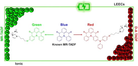
We designed and synthesized two new ionic thermally activated delayed fluorescent (TADF) emitters that are charged analogues of a known multiresonant TADF (MR-TADF) compound, DiKTa. The emission of the charged derivatives is red-shifted compared to the parent compound. For instance, DiKTa-OBuIm emits in the green (λPL = 499 nm, 1 wt % in mCP) while DiKTa-DPA-OBuIm emits in the red (λPL = 577 nm, 1 wt % in mCP). In 1 wt % mCP films, both emitters showed good photoluminescence quantum yields of 71% and 61%, and delayed lifetimes of 316.6 μs and 241.7 μs, respectively, for DiKTa-OBuIm and DiKTa-DPA-OBuIm, leading to reverse intersystem crossing rates of 2.85 × 10³ s−1 and 3.04 × 10³ s−1. Light-emitting electrochemical cells were prepared using both DiKTa-OBuIm and DiKTa-DPA-OBuIm as active emitters showing green (λmax = 534 nm) and red (λmax = 656 nm) emission, respectively.
Light-emitting electrochemical cells (LEECs) are thin film light-emitting devices typically consisting of an emissive layer containing ionic species that facilitate charge transport and an emissive semiconductor material. The emissive layer is sandwiched between two air-stable electrodes [1]. Upon application of an external bias the ions in the active layer migrate to the corresponding electrodes, resulting in the formation of electrical double layers (EDLs) at the interface of the electrodes. The EDLs facilitate charge injection into the emissive layer regardless of the energy levels of the electroactive species and work function of the electrodes. Injection of electrons and holes creates oxidized and reduced species near the anode and cathode, respectively. These oxidized and reduced species are stabilized by the ions to form a p-i-n junction in the bulk of the emissive layer and emission takes place within the intrinsic region [2-6].
Two families of widely investigated emitters for LEECs are ionic transition metal complexes (iTMCs) [7-10] and conjugated polymers (CPs) [4]. From the early use of ruthenium(II) complexes, a significant amount of research has focussed on developing high-performance iTMC-based LEECs [11,12], with iridium(III) complexes typically showing the greatest potential. A detracting feature of many iTMC LEECs is the use of scarce noble metal complexes. Despite the enormous number of low molecular weight organic emitters designed for use in organic light-emitting diodes (OLEDs), relatively little attention has been devoted to the design of ionic small molecule (SM) [13] organic emitters for LEECs. The majority of the reported SM emitters for LEECs are fluorescent in nature and so the internal quantum efficiency (IQE) of the device is limited to 25% [13]. Thermally activated delayed fluorescent (TADF) emitters are one class of purely organic materials that can harvest triplet excitons in electroluminescent (EL) devices through a triplet to singlet reverse intersystem crossing (RISC) upconversion process [14]. Indeed, OLEDs using TADF emitters can achieve up to 100% IQE, comparable to devices using phosphorescent emitters [15].
Purely organic TADF emitters have not been widely investigated for use in LEECs. We reported the first organic TADF LEEC, I (Figure 1a, original compound 2 in [16]), in 2015 by adapting the structure of the known TADF emitter 2CzPN with imidazolium groups [16,17] (Figure 1a). The LEEC devices showed a maximum external quantum efficiency (EQEmax) of 0.39%, a maximum brightness (Bmax) of 13 cd m−2, and a peak electroluminescence (λEL) at 538 nm. The device performance suffered when the emissive layer was doped with an ionic liquid (EQEmax = 0.12%, Bmax = 10 cd m−2), which was incorporated to increase charge mobility within the emissive layer. We later showed that this emitter could act as host material in combination with a cyanine dye emitter [18]. The EQEmax for this host–guest device was higher than for the non-doped device, at 2.0% demonstrated 100% exciton utilization efficiency in the device and efficient energy transfer from the host to the guest cyanine emitter. Deep blue emission in LEECs is challenging. We also reported a blue-emitting LEEC employing a cationic sulfone-based donor–acceptor TADF emitter, imCzDPS (λPL = 440 nm, ΦPL = 44%, neat film) [19]. The EL of the LEEC was red-shifted at λEL of 470 nm compared to the PL. Following these initial reports Edman and co-workers demonstrated how neutral TADF small molecules [20], polymers [21], and dendrimers [22] could be employed in LEECs where the emissive layer also contained an inorganic salt and a conducting polymer. Recently, a step-change in device performance were achieved by He et al. who employed a cationic TADF compound that possesses low-lying through-space and through-bond charge transfer excited states [23]. The LEEC showed a green EL with a peak brightness of 572 cd m−2 and an EQEmax of 6.8% at 4.0 V. The half-life of their device reached 218 h at a brightness of 162 cd m−2. Recently, Su et al. reported two ionic TADF emitters incorporating a pyridinium moiety, Pym-CZ and Pym-tBuCZ as the acceptor and carbazole or tert-butylcarbazole as donor groups [24]. Pym-CZ showed red emission in dichloromethane (λPL = 691 nm, ΦPL = 43%) and in the neat film (λPL = 583 nm, ΦPL = 15%). The emission is further red-shifted and attenuated in Pym-tBuCZ in dichloromethane (λPL = 740 nm, ΦPL = 8%) and in the neat film (λPL = 593 nm, ΦPL = 6%). The LEECs with Pym-CZ (λEL = 599 nm, Bmax = 8.69 cd m−2, EQEmax = 0.91%) and Pym-tBuCZ (λEL = 618 nm, Bmax = 1.96 cd m−2, EQEmax = 0.05%) are the first examples of orange-red devices employing purely organic intrinsically ionic TADF emitters. Though these reports hint at the potential of TADF emitters in LEECs, the emission in these devices is typically broad, reflective of the charge transfer (CT) character of the emission, and so colour purity suffers.
Figure 1:
Chemical structures of (a) reported ionic TADF emitters for LEECs, (b) the MR-TADF emitter DiKTa and selected derivatives, and (c) the ionic emitters in this work.
Figure 1:
Chemical structures of (a) reported ionic TADF emitters for LEECs, (b) the MR-TADF emitter DiKTa an...
Narrowband emission has, however, been demonstrated in multiresonant TADF (MR-TADF) materials. MR-TADF compounds, first introduced by Hatakeyama and co-workers, are typically p- and n-doped nanographenes [25,26]. OLEDs using MR-TADF emitters can simultaneously achieve narrowband emission and very high EQEmax. Inspired by our recent work on neutral MR-TADF emitters for OLEDs [27,28], we designed two charged analogues of DiKTa[29] (Figure 1b), to make them amenable for use as emitters in LEECs, DiKTa-OBuIm and DiKTa-DPA-OBuIm (Figure 1c). In 1 wt % doped mCP films, DiKTa-OBuIm emits in the green region (λPL = 499 nm, ΦPL = 71%, 1 wt % in mCP) and DiKTa-DPA-OBuIm is a red emitter (λPL = 577 nm, ΦPL = 61%, 1 wt % in mCP). The presence of the DPA group in DiKTa-DPA-OBuIm transforms this compound from one that is MR-TADF to one that is better described as a donor–acceptor TADF, which is reflected in the red-shifted and broadened emission [28].
Results and Discussion
DiKTa-OBuIm was obtained in three steps (Scheme 1) in 23% overall yield. First, hydrolysis of 1, in situ conversion to the acyl chloride and subsequent Lewis acid-promoted Friedel–Crafts acylation reaction produced compound 2 (Scheme 1), where the AlCl3 was also responsible for the demethylation. Compound 2 was then subjected to monoalkylation with 1,4-dibromobutane in moderate yield, followed by a second alkylation step with 1-methylimidazole in very good yield. DiKTa-OBuIm was isolated as its hexafluorophosphate salt following anion metathesis with NH4PF6. DiKTa-DPA-OBuIm was obtained also in three steps at 35% overall yield from compound 4 using a similar synthetic strategy, which itself was synthesized from Br-DiKTa[28] following a Buchwald–Hartwig coupling. Details of the synthesis are found in Supporting Information File 1. The identity and purity of the molecules were verified using a combination of 1H and 13C NMR spectroscopy, high resolution mass spectrometry (HRMS) (Figures S1–S24 in Supporting Information File 1), and melting point analysis.
Scheme 1:
Synthesis of DiKTa-OBuIm and DiKTa-DPA-OBuIm.
Scheme 1:
Synthesis of DiKTa-OBuIm and DiKTa-DPA-OBuIm.
We modelled the electron density distribution in DiKTa-OBuIm and DiKTa-DPA-OBuIm using density functional theory (DFT) calculations in the ground state, at the PBE0/6-31G(d,p) level of theory in the gas phase (Figure 2a). The calculations were based on model systems, DiKTa-OMe and DiKTa-DPA-OMe, respectively, wherein we replaced the imidazolium side chain of DiKTa-OBuIm and DiKTa-DPA-OBuIm, respectively, with a methyl group [30]. Compared to DiKTa (HOMO = −6.20 eV, LUMO = −2.23 eV, ΔEg = 3.97 eV), both emitters possess a smaller HOMO–LUMO gap. The HOMO is more strongly affected by the incorporation of donor units [28]. For instance, in the case of Cz-DiKTa and DMAC-DiKTa the HOMO is destabilized by 0.47 eV and 0.94 eV, respectively, compared to DiKTa[28]. The lowest unoccupied molecular orbital (LUMO) for both compounds is localized on the DiKTa core (Figure S25 in Supporting Information File 1). This orbital is only slightly stabilized in DiKTa-DPA-OMe due to the presence of the more strongly electron-donating DPA group. The highest occupied molecular orbital (HOMO) in DiKTa-OMe is also localized on the DiKTa core and the electron density distribution of this molecule is reminiscent of that of a MR-TADF compound and is nearly identical to that of the parent emitter, DiKTa[27] (Figure S25 in Supporting Information File 1). There is a very large change in both the electron density distribution and the HOMO energy between the two emitters. For DiKTa-DPA-OMe, the HOMO is mainly localized on the DPA unit but with some delocalization onto the DiKTa core, resulting in a destabilization of this orbital from −5.91 eV in DiKTa-OMe to −5.19 eV in DiKTa-DPA-OMe. The HOMO–LUMO gap, ΔEg, thus decreases to 3.08 eV compared to that of DiKTa-OMe (3.74 eV). The excited states were modelled using spin-component scaling second-order approximate coupled-cluster (SCS-CC2) in tandem with the cc-pVDZ basis set (Table S1 in Supporting Information File 1). Figure 2b shows the difference density plots for singlet (S) and triplet (T) excited states for DiKTa-OMe and DiKTa-DPA-OMe. Compared to DiKTa (S1 = 3.45 eV, T1 = 3.18 eV, f = 0.20, ΔEST = 0.27 eV) [28], the lowest-lying singlet (S1) and triplet (T1) states are stabilized in the case of DiKTa-OMe, while the singlet–triplet energy gap, ΔEST, remained the same at 0.27 eV. The nature of S1 and T1 resemble to those of its parent DiKTa and so this compound is likely to behave as a MR-TADF emitter. The nature of the S2 state is n–π* in DiKTa-OMe. The excited state picture of DiKTa-DPA-OMe is different to that of other reported D–A-type systems containing DiKTa as the acceptor [28]. Long range charge transfer is not apparent here and instead the coupled cluster calculations predict a compound that is MR-TADF but where the electron density distribution is delocalized over the entire molecule. Compared to DiKTa-OMe, both S1 and T1 of DiKTa-DPA-OMe are stabilized to 3.07 eV and 2.83 eV, respectively. The ΔEST decreases to 0.24 eV and there is no intermediate triplet state. The trend of stabilized S1 and T1 states when a donor group decorates the DiKTa core (S1 = 3.45 eV, T1 = 3.18 eV) has been previously observed in reported emitters such as Cz-DiKTa (S1 = 3.35 eV, T1 = 3.09 eV) and DMAC-DiKTa (S1 = 3.43 eV, T1 = 3.17 eV) [28]. We also calculated the charge transfer character of each excited state, focussing on the distance of charge transfer (DCT). When considering the S1 excited state, there is an increase in CT character moving from DiKTa, DiKTa-OMe, and DiKTa-DPA-OMe (DCT = 1.45 Å, 1.81 Å, and 3.34 Å, respectively) reflected in the increased donor strength.
Figure 2:
(a) HOMO and LUMO electron density distribution and orbital energies of DiKTa-OMe and DiKTa-DPA-OMe calculated at the PBE0/6-31G(d,p) level of theory in the gas phase, isovalue = 0.02; (b) difference density plots and energies for the two lowest-lying singlet and triplet excited states for DiKTa-OMe and DiKTa-DPA-OMe calculated at SCS-CC2/cc-pVDZ in the gas phase (isovalue = 0.001). The blue color represents an area of decreased electron density, and yellow represents an increased electron density between the ground and excited states; f denotes the oscillator strength for the transition to the excited singlet state.
Figure 2:
(a) HOMO and LUMO electron density distribution and orbital energies of DiKTa-OMe and DiKTa-DPA-OMe...
The electrochemical properties of DiKTa-OBuIm and DiKTa-DPA-OBuIm were investigated by cyclic voltammetry (CV) and differential pulse voltammetry (DPV) in acetonitrile with 0.1 M tetra-n-butylammonium hexafluorophosphate as the supporting electrolyte (Figure 3a and Table S2 in Supporting Information File 1). The oxidation and reduction of both emitters showed good reversibility, which is beneficial for better performance in LEEC devices [31]. The oxidation potentials, Eox, determined from the peak value of the first DPV curve are 1.05 V and 0.44 V for DiKTa-OBuIm and DiKTa-DPA-OBuIm, respectively, which correspond to HOMO energy levels of −5.85 eV and −5.24 eV, respectively. The trend of a destabilized HOMO energy level from DiKTa-OBuIm to DiKTa-DPA-OBuIm is predicted by DFT calculations. DiKTa possesses an oxidation potential of 1.66 V and an associated HOMO energy level of −5.93 eV. The reduction potentials, Ered, are −1.67 V and −1.61 V, respectively, for DiKTa-OBuIm and DiKTa-DPA-OBuIm. The corresponding LUMO levels are −3.13 eV and −3.18 eV for DiKTa-OBuIm and DiKTa-DPA-OBuIm, respectively. The LUMO values of both emitters match that of DiKTa (−3.11 eV), which suggests that reduction occurs on the DiKTa core in both compounds, a contention corroborated by the DFT calculations. The electrochemical gap reduced from 2.72 V in DiKTa-OBuIm to 2.06 V in DiKTa-DPA-OBuIm, a trend that is in line with the DFT calculations.
Figure 3:
(a) Cyclic and differential pulse voltammograms measured in degassed MeCN with 0.1 M [n-Bu4N]PF6 as the supporting electrolyte and Fc+/Fc as the internal reference (0.38 V vs SCE) [32]. Scan rate = 100 mV s−1; (b) solution-state photophysical measurements: absorption and steady-state emission spectra at 300 K measured in MeCN. λexc = 453 nm for DiKTa-OBuIm and λexc = 488 nm for DiKTa-DPA-OBuIm.
Figure 3:
(a) Cyclic and differential pulse voltammograms measured in degassed MeCN with 0.1 M [n-Bu4N]PF6 as...
Figure 3b shows the solution-state photophysical properties of DiKTa-OBuIm and DiKTa-DPA-OBuIm in acetonitrile and the data are compiled in Table 1. The lowest energy absorption band for DiKTa-OBuIm at 453 nm (ε = 17 × 103 M−1 cm−1) is red-shifted and slightly more intense than that of the parent DiKTa at 436 nm, (ε = 14 × 103 M−1 cm−1) [27] owing to the increased conjugation in DiKTa-OBuIm. For the emitter 7a (Figure 1b) [33] reported by Yan et al. the red-shift of the lowest energy absorption band was more pronounced than that in DiKTa-OBuIm. This band is assigned to a short-range charge transfer transition (SRCT) that is a hallmark characteristic in MR-TADF compounds [28]. The Stokes shift is 54 nm (2361 cm−1) for DiKTa-OBuIm. The lowest energy absorption band in DiKTa-DPA-OBuIm is red-shifted and less intense (ε = 6 × 10³ M−1 cm−1) compared to DiKTa-OBuIm, in line with its decreased oscillator strength (vide supra). According to the calculations (vide supra), the S1 excited state is also SRCT, but with larger long-range charge transfer (LRCT) content. Owing to the relative flexibility around the DPA donor unit, the Stokes shift is larger at 75 nm (2761 cm−1). DiKTa-OBuIm and DiKTa-DPA-OBuIm exhibited broad green (λPL = 507 nm, FWHM = 75 nm) and red (λPL = 563 nm, FWHM = 92 nm) emissions in MeCN, respectively, which is larger than DiKTa (46 nm in MeCN) [27] in line with the greater LRCT character for these emitters; this observation has been noted for other donor decorated MR-TADF emitters [34-36]. The photoluminescence quantum yield, ΦPL, in MeCN for DiKTa-OBuIm is 48% which decreases in air to 34%. The emission is much weaker in DiKTa-DPA-OBuIm, reflecting both the smaller oscillator strength of the transition to S1 and the greater non-radiative decay due to the energy gap law (ΦPL = 11% and 7% under vacuum and in air, respectively) in MeCN [37]. The S1 and T1 levels were measured from the onsets of fluorescence (2.66 eV) and phosphorescence spectra (2.41 eV) in 2-MeTHF glass at 77 K (Figure S26, Supporting Information File 1). DiKTa-OBuIm possesses a ΔEST of 0.25 eV. Unfortunately, DiKTa-DPA-OBuIm was insoluble in 2-MeTHF and so the measurement could not be made. No delayed component was observed in MeCN solution under vacuum for either of the compounds (Figure S27 in Supporting Information File 1).
Table 1:
Photophysical properties of DiKTa-OBuIm and DiKTa-DPA-OBuIm.
Compound
Medium
λAbsa [nm]
λPLb [nm]
FWHMc [nm]
ES1d [eV]
ET1d [eV]
∆ESTe [eV]
DiKTa-OBuIm
sol.f
453 (17)
507
75
2.66
2.41
0.25
filmg
–
500
66
2.65
2.45
0.20
DiKTa-DPA-OBuIm
sol.f
488 (6)
563
92
–
–
–
filmg
–
578
95
2.40
2.21
0.19
ΦPLh [%]
τpi [ns]
τdi [μs]
kISCj [s−1] (×107)
kRISCj [s−1] (×103)
ks_rj [s−1] (×107)
ks_nrj [s−1] (×107)
DiKTa-OBuIm
48a
14.3a
–
–
–
–
–
71 (57)b
8.7 b
316.6b
3.59 ± 1.3
2.85 ± 1.1
6.60
2.69
DiKTa-DPA-OBuIm
11a
12.7a
–
–
–
–
–
61 (53)b
14.1b
241.7b
2.21 ± 1.2
3.04 ± 1.7
3.78
2.38
aLowest energy absorbance band, absorptivity (ε) in parentheses (/ × 103 M−1 s−1). bSteady-state emission maximum at 300 K; λexc = 340 nm. cFull width at half maximum of the emission peak. dS1 and T1 energies were obtained from the onsets of the respective prompt fluorescence (delay: 1 ns; gate time: 100 ns) and phosphorescence spectra (delay: 1 ms; gate time: 9 ms) at 77 K; λexc = 343 nm. eΔEST = E(S1) − E(T1). fIn MeCN solutions (10−6 M). gMeasured in spin-coated thin films consisting of 1.0 wt % emitter in mCP; λexc = 340 nm. hΦPL in solutions were measured by the relative method using quinine sulfate as a standard (Φr = 54.6% in 1 N H2SO4) [38], while absolute ΦPL of thin films were measured using an integrating sphere; λexc = 340 nm under nitrogen and the values in parentheses are in the presence of O2. iPrompt and delayed lifetimes in solutions and thin films obtained by TCSPC and MCS, λexc = 379 nm. jIntersystem and reverse intersystem crossing rates were calculated using the steady-state approximation method as described in literature [39].
The thin film PL behavior of both emitters was then assessed in 1 wt % doped film in 1,3-di-9-carbazolylbenzene (mCP) (Figure 4). At this doping concentration, the photophysical properties should reflect monomolecular entities. Emission was observed at 500 nm (FWHM = 66 nm) and 578 nm (FWHM = 95 nm) for DiKTa-OBuIm and DiKTa-DPA-OBuIm, respectively. The emission spectrum of DiKTa-OBuIm is slightly blue-shifted and narrower than that in MeCN, which is expected due to the higher polarity of the solvent than mCP. Surprisingly, for DiKTa-DPA-OBuIm the emission is red-shifted by 14 nm, and with negligible change in the FWHM. This suggests that the conformation of the emitter in the solid state is slightly more conjugated than that in solution or that there are specific host–guest interactions with the DPA unit that perturbs the energy of the excited state. The emission is broader than that of a structurally similar emitter, QAD-mTDPA, a derivative of DiKTa containing two DPA substituents, reported by Zhang et al. [40] The structure of QAD-mTDPA (λPL = 587 nm, FWHM = 62 nm, ΦPL = 97%, ΔEST = 0.33 eV, τD = 269 μs, 1.5 wt % CBP) is shown in Figure 1b. Both emitters showed red-shifted and broadened emission compared to that of DiKTa (λPL = 466 nm, FWHM = 40 nm, ΦPL = 70%, ΔEST = 0.20 eV, τD = 168 μs, 2 wt % mCP) in the same host [28]. Both emitters exhibited high ΦPL values in the mCP film at 71% and 61% under nitrogen, and these reduced to 57% and 53% in air for DiKTa-OBuIm and DiKTa-DPA-OBuIm, respectively. As neat thin films, the emission for both compounds are red-shifted and significantly quenched (Figure S28 in Supporting Information File 1); indeed, the ΦPL for the neat film of DiKTa-OBuIm is only 9% while we could not ascertain a reliable value for DiKTa-DPA-OBuIm. Severe aggregation-caused quenching of the emission in the neat film was also observed for DiKTa (ΦPL = 11%, under N2) [27]. The S1 and T1 levels were measured from the onsets of fluorescence and phosphorescence spectra in the 1 wt % doped mCP film at 77 K (Figure S29 in Supporting Information File 1). The corresponding ΔEST values are 0.20 eV and 0.19 eV, respectively, for DiKTa-OBuIm and DiKTa-DPA-OBuIm, which are nearly same to that reported for DiKTa (ΔEST = 0.20 eV) [28]. Experimental ΔEST values are smaller than those computationally predicted (0.27 eV and 0.24 eV, respectively for DiKTa-OBuIm and DiKTa-DPA-OBuIm). However, the trend of decreasing ΔEST is in line to the findings from DFT. The temperature dependent time-resolved PL decays in the 1 wt % doped mCP films are presented in Figure 4b and c. Both emitters show prompt and delayed emission components with an enhancement of the delayed emission with increasing temperature, a feature of TADF. Unlike the delayed emission lifetime of DiKTa (15 μs in 3.5 wt % mCP, 23 μs in PhMe) [27], and its derivatives such as Cz-DiKTa (τD = 196 μs, 2 wt % mCP), DMAC-DiKTa (τD = 6.6 μs, 2 wt % mCP), and QAD-mTDPA (τD = 168 μs, in 2 wt % mCP) in Figure 1b[28,40], the delayed lifetimes from DiKTa-OBuIm and DiKTa-DPA-OBuIm are long at 317 μs and 242 μs, respectively. RISC rate constants, kRISC, were calculated for both emitters, which are 2.85 × 10³ s−1 and 3.04 × 10³ s−1, respectively for DiKTa-OBuIm and DiKTa-DPA-OBuIm, compared to that of DiKTa (4.6 × 10⁴ s−1) in toluene [27,39].
Figure 4:
(a) Steady-state emission spectra of DiKTa-OBuIm and DiKTa-DPA-OBuIm in 1 wt % doped mCP films, λexc. = 340 nm; (b) temperature-dependent time resolved PL decays of DiKTa-OBuIm in 1 wt % doped mCP films. Inset: prompt PL decay of DiKTa-OBuIm; (c) temperature-dependent time resolved PL decays of DiKTa-DPA-OBuIm in 1 wt % doped mCP films. Inset: prompt PL decay of DiKTa-DPA-OBuIm, λexc. = 379 nm.
Figure 4:
(a) Steady-state emission spectra of DiKTa-OBuIm and DiKTa-DPA-OBuIm in 1 wt % doped mCP films, λex...
LEECs were fabricated using DiKTa-OBuIm and DiKTa-DPA-OBuIm as emitters. The device stack was the following: ITO/PEDOT:PSS/emitter/Al (where ITO is indium tin oxide; PEDOT:PSS is poly(3,4-ethylenedioxythiophene):poly(styrenesulfonate)). The PEDOT:PSS and the emitter layers were prepared from solution and the device was finished with an evaporated Al top contact. Details of the LEEC fabrication can be found in the General Methods section of Supporting Information File 1. Driven by their promising ΦPL LEEC devices using DiKTa-OBuIm and DiKTa-DPA-OBuIm as 1 wt % doped films in mCP as the emitter layer were prepared. The devices showed no turn-on, both in lifetime measurements and in current density and luminance versus voltage sweeps (JVL) up to 8 V. Most likely the low content of ionic species in the neutral matrix hindered the required ionic transport for LEEC operation. To solve this, we fabricated devices adding an ionic liquid (lithium hexafluorophosphate (LiPF6) or 1-butyl-3-methylimidazolium hexafluorophosphate (BMIM:PF6) in a 4 to 1 molar ratio) and, in some cases, an electrolyte matrix (PEO (polyethylene oxide)), to improve the ionic mobility on the active film [5,41]. However, despite these efforts, still no emission was observed when the devices were biased. Next, neat films of DiKTa-OBuIm and DiKTa-DPA-OBuIm were directly used as active layers. Non-doped small molecule films have shown recently promising results in LEEC devices [42]. As both emitters are ionic, in principle there is no need to incorporate additional mobile ions. A host–guest approach, using 1 wt % of DiKTa-DPA-OBuIm in DiKTa-OBuIm was also used, the latter acting as a host matrix for the former. The electroluminescence (EL) of the three device stacks is shown in Figure 5a. Similar to the PL, the EL spectra are broad and unstructured. The EL of DiKTa-OBuIm and DiKTa-DPA-OBuIm occurs at λEL of 534 and 656 nm, respectively. Both neat-film EL spectra are red-shifted from the solution state and the 1 wt % in mCP film PL spectra. The origin of this red shift could be ascribed to the presence of emissive aggregates in the emissive layer [19]. Interestingly, in the host–guest system the energy transfer is not complete and both molecules are responsible for the electroluminescence, with a λEL at 586 nm, between the emission of the neat films. JVL characterization (from −2 to 8 V) was carried out on the three stacks (Figure 5b–d). As it can be seen, the current density reaches high values, and the injection is primarily dominated by ohmic behavior. The device with DiKTa-DPA-OBuIm shows a steeper injection reaching values of 10,000 A m−2 at 8 V when compared with the device with DiKTa-OBuIm, which shows a current density of 1000 A m−2 at the same voltage value. The current density in the device with the host–guest system is dominated by the presence of DiKTa-OBuIm. Light emission is detected at around ≈5 V, with values of 15 cd m−2 for the device with DiKTa-DPA-OBuIm and around 2 cd m−2 for the devices with DiKTa-OBuIm and the host–guest system, each at 8 V. From the EL spectra it is possible to estimate the external quantum efficiency (EQE) values; however, they are also highly affected by the luminance levels, giving as a result very low efficiencies (<0.01%).
Figure 5:
(a) Electroluminescence spectra of DiKTa-OBuIm (green curve), DiKTa-DPA-OBuIm (red curve) and 1% of DiKTa-DPA-OBuIm in DiKTa-OBuIm (black curve). Current (black) and luminance (blue) versus voltage (JVL) sweep (from −2 to 8 V) of (b) DiKTa-OBuIm, (c) DiKTa-DPA-OBuIm, and (d) 1% of DiKTa-DPA-OBuIm in DiKTa-OBuIm.
Figure 5:
(a) Electroluminescence spectra of DiKTa-OBuIm (green curve), DiKTa-DPA-OBuIm (red curve) and 1% of ...
Two new ionic TADF emitters were designed and synthesized for LEECs application using a known MR-TADF emitter DiKTa. Our MR-TADF green emitter, DiKTa-OBuIm exhibited efficient green luminescence and TADF in 1 wt % mCP film (λPL = 499 nm, FWHM = 66 nm, ΦPL = 71%, τd = 317 μs, kRISC = 2.85 × 10³ s−1). This emitter represents a rare example of an ionic MR-TADF emitter for LEEC applications. The red emitter, DiKTa-DPA-OBuIm, was obtained by coupling a methoxy-modified diphenylamine unit onto the DiKTa fragment. Addition of a donor unit red-shifted the emission to red region with TADF (λPL = 577 nm, FWHM = 95 nm, ΦPL = 61%, τd = 242 μs, kRISC = 3.04 × 10³ s−1, 1 wt % in mCP). Different strategies were explored to prepare LEECs based on DiKTa-OBuIm and DiKTa-DPA-OBuIm as emitters. The devices showed green and red emission, respectively.
Supporting Information File 1: 1H NMR and 13C NMR spectra, GC–MS, and HRMS; supplementary computational data and coordinates; additional photophysical.
We thank Dr. David Hall for providing help with the calculations and initial samples of some of the intermediates.
Funding
M. K. would like to thank 2214-A International Research Fellowship Programme for Ph.D. students (1059B141900585). This project has received funding from the European Union’s Horizon 2020 research and innovation programme under the Marie Skłodowska Curie grant agreement No 838885 (NarrowbandSSL). S.M.S. acknowledges support from the Marie Skłodowska-Curie Individual Fellowship (grant agreement No 838885 NarrowbandSSL). A. K. G. is grateful to the Royal Society for Newton International Fellowship NF171163. L.M acknowledges that the project who gave rise to these results received support from the European Research Council (ERC) under the European Union’s Horizon 2020 research and innovation programme Grant agreement No. 834431, the Spanish Ministry of Science, Innovation and Universities (MICIU, RTI2018-095362-A-I00, and EQC2018-004888-P) and the Comunitat Valenciana (IDIFEDER/2020/063 and PROMETEU/2020/077). D.T. acknowledges support from the Comunitat Valenciana (CIGE/2021/0).
References
Pei, Q.; Costa, R. D. Adv. Funct. Mater.2020,30, 2002879. doi:10.1002/adfm.202002879
Return to citation in text:
[1]
van Reenen, S.; Matyba, P.; Dzwilewski, A.; Janssen, R. A. J.; Edman, L.; Kemerink, M. J. Am. Chem. Soc.2010,132, 13776–13781. doi:10.1021/ja1045555
Return to citation in text:
[1]
Lindh, E. M.; Lundberg, P.; Lanz, T.; Edman, L. Sci. Rep.2019,9, 10433. doi:10.1038/s41598-019-46860-y
Return to citation in text:
[1]
Mindemark, J.; Edman, L. J. Mater. Chem. C2016,4, 420–432. doi:10.1039/c5tc03429a
Return to citation in text:
[1]
[2]
Ràfols‐Ribé, J.; Zhang, X.; Larsen, C.; Lundberg, P.; Lindh, E. M.; Mai, C. T.; Mindemark, J.; Gracia‐Espino, E.; Edman, L. Adv. Mater. (Weinheim, Ger.)2022,34, 2107849. doi:10.1002/adma.202107849
Return to citation in text:
[1]
Bai, R.; Meng, X.; Wang, X.; He, L. Adv. Funct. Mater.2020,30, 1907169. doi:10.1002/adfm.201907169
Return to citation in text:
[1]
Zhang, C.; Liu, R.; Zhang, D.; Duan, L. Adv. Funct. Mater.2020,30, 1907156. doi:10.1002/adfm.201907156
Return to citation in text:
[1]
Hu, T.; He, L.; Duan, L.; Qiu, Y. J. Mater. Chem.2012,22, 4206–4215. doi:10.1039/c2jm16185k
Return to citation in text:
[1]
Housecroft, C. E.; Constable, E. C. J. Mater. Chem. C2022,10, 4456–4482. doi:10.1039/d1tc04028f
Return to citation in text:
[1]
Costa, R. D.; Ortí, E.; Bolink, H. J.; Monti, F.; Accorsi, G.; Armaroli, N. Angew. Chem., Int. Ed.2012,51, 8178–8211. doi:10.1002/anie.201201471
Return to citation in text:
[1]
Henwood, A. F.; Zysman-Colman, E. Top. Curr. Chem.2016,374, 36. doi:10.1007/s41061-016-0036-0
Return to citation in text:
[1]
Kanagaraj, S.; Puthanveedu, A.; Choe, Y. Adv. Funct. Mater.2020,30, 1907126. doi:10.1002/adfm.201907126
Return to citation in text:
[1]
[2]
Wong, M. Y.; Zysman-Colman, E. Adv. Mater. (Weinheim, Ger.)2017,29, 1605444. doi:10.1002/adma.201605444
Return to citation in text:
[1]
Nakanotani, H.; Tsuchiya, Y.; Adachi, C. Chem. Lett.2021,50, 938–948. doi:10.1246/cl.200915
Return to citation in text:
[1]
Wong, M. Y.; Hedley, G. J.; Xie, G.; Kölln, L. S.; Samuel, I. D. W.; Pertegás, A.; Bolink, H. J.; Zysman-Colman, E. Chem. Mater.2015,27, 6535–6542. doi:10.1021/acs.chemmater.5b03245
Return to citation in text:
[1]
[2]
Uoyama, H.; Goushi, K.; Shizu, K.; Nomura, H.; Adachi, C. Nature2012,492, 234–238. doi:10.1038/nature11687
Return to citation in text:
[1]
Pertegás, A.; Wong, M. Y.; Sessolo, M.; Zysman-Colman, E.; Bolink, H. J. ECS J. Solid State Sci. Technol.2016,5, R3160–R3163. doi:10.1149/2.0201601jss
Return to citation in text:
[1]
Wong, M. Y.; La-Placa, M.-G.; Pertegas, A.; Bolink, H. J.; Zysman-Colman, E. J. Mater. Chem. C2017,5, 1699–1705. doi:10.1039/c6tc04821h
Return to citation in text:
[1]
[2]
Lundberg, P.; Tsuchiya, Y.; Lindh, E. M.; Tang, S.; Adachi, C.; Edman, L. Nat. Commun.2019,10, 5307. doi:10.1038/s41467-019-13289-w
Return to citation in text:
[1]
Lundberg, P.; Wei, Q.; Ge, Z.; Voit, B.; Reineke, S.; Edman, L. J. Phys. Chem. Lett.2020,11, 6227–6234. doi:10.1021/acs.jpclett.0c01506
Return to citation in text:
[1]
Matsuki, K.; Pu, J.; Takenobu, T. Adv. Funct. Mater.2020,30, 1908641. doi:10.1002/adfm.201908641
Return to citation in text:
[1]
Yu, R.; Song, Y.; Zhang, K.; Pang, X.; Tian, M.; He, L. Adv. Funct. Mater.2022,32, 2110623. doi:10.1002/adfm.202110623
Return to citation in text:
[1]
Shen, H.-L.; Hsiao, P.-W.; Yi, R.-H.; Su, Y.-H.; Chen, Y.; Lu, C.-W.; Su, H.-C. Dyes Pigm.2022,203, 110346. doi:10.1016/j.dyepig.2022.110346
Return to citation in text:
[1]
Hirai, H.; Nakajima, K.; Nakatsuka, S.; Shiren, K.; Ni, J.; Nomura, S.; Ikuta, T.; Hatakeyama, T. Angew. Chem., Int. Ed.2015,54, 13581–13585. doi:10.1002/anie.201506335
Return to citation in text:
[1]
Madayanad Suresh, S.; Hall, D.; Beljonne, D.; Olivier, Y.; Zysman‐Colman, E. Adv. Funct. Mater.2020,30, 1908677. doi:10.1002/adfm.201908677
Return to citation in text:
[1]
Hall, D.; Suresh, S. M.; dos Santos, P. L.; Duda, E.; Bagnich, S.; Pershin, A.; Rajamalli, P.; Cordes, D. B.; Slawin, A. M. Z.; Beljonne, D.; Köhler, A.; Samuel, I. D. W.; Olivier, Y.; Zysman‐Colman, E. Adv. Opt. Mater.2020,8, 1901627. doi:10.1002/adom.201901627
Return to citation in text:
[1]
[2]
[3]
[4]
[5]
[6]
[7]
Wu, S.; Li, W.; Yoshida, K.; Hall, D.; Madayanad Suresh, S.; Sayner, T.; Gong, J.; Beljonne, D.; Olivier, Y.; Samuel, I. D. W.; Zysman-Colman, E. ACS Appl. Mater. Interfaces2022,14, 22341–22352. doi:10.1021/acsami.2c02756
Return to citation in text:
[1]
[2]
[3]
[4]
[5]
[6]
[7]
[8]
[9]
[10]
[11]
[12]
Yuan, Y.; Tang, X.; Du, X.-Y.; Hu, Y.; Yu, Y.-J.; Jiang, Z.-Q.; Liao, L.-S.; Lee, S.-T. Adv. Opt. Mater.2019,7, 1801536. doi:10.1002/adom.201801536
Return to citation in text:
[1]
Subeesh, M. S.; Shanmugasundaram, K.; Sunesh, C. D.; Chitumalla, R. K.; Jang, J.; Choe, Y. J. Phys. Chem. C2016,120, 12207–12217. doi:10.1021/acs.jpcc.6b03710
Return to citation in text:
[1]
Tang, S.; Sandström, A.; Lundberg, P.; Lanz, T.; Larsen, C.; van Reenen, S.; Kemerink, M.; Edman, L. Nat. Commun.2017,8, 1190. doi:10.1038/s41467-017-01339-0
Return to citation in text:
[1]
Connelly, N. G.; Geiger, W. E. Chem. Rev.1996,96, 877–910. doi:10.1021/cr940053x
Return to citation in text:
[1]
Yan, C.; Shang, R.; Nakamoto, M.; Yamamoto, Y.; Adachi, Y. Chem. Lett.2020,49, 457–460. doi:10.1246/cl.200089
Return to citation in text:
[1]
Yang, M.; Park, I. S.; Yasuda, T. J. Am. Chem. Soc.2020,142, 19468–19472. doi:10.1021/jacs.0c10081
Return to citation in text:
[1]
Qi, Y.; Ning, W.; Zou, Y.; Cao, X.; Gong, S.; Yang, C. Adv. Funct. Mater.2021,31, 2102017. doi:10.1002/adfm.202102017
Return to citation in text:
[1]
Xu, Y.; Li, C.; Li, Z.; Wang, Q.; Cai, X.; Wei, J.; Wang, Y. Angew. Chem., Int. Ed.2020,59, 17442–17446. doi:10.1002/anie.202007210
Return to citation in text:
[1]
Serevičius, T.; Skaisgiris, R.; Dodonova, J.; Fiodorova, I.; Genevičius, K.; Tumkevičius, S.; Kazlauskas, K.; Juršėnas, S. J. Phys. Chem. Lett.2022,13, 1839–1844. doi:10.1021/acs.jpclett.1c03810
Return to citation in text:
[1]
Melhuish, W. H. J. Phys. Chem.1961,65, 229–235. doi:10.1021/j100820a009
Return to citation in text:
[1]
Tsuchiya, Y.; Diesing, S.; Bencheikh, F.; Wada, Y.; dos Santos, P. L.; Kaji, H.; Zysman-Colman, E.; Samuel, I. D. W.; Adachi, C. J. Phys. Chem. A2021,125, 8074–8089. doi:10.1021/acs.jpca.1c04056
Return to citation in text:
[1]
[2]
Alahbakhshi, M.; Mishra, A.; Haroldson, R.; Ishteev, A.; Moon, J.; Gu, Q.; Slinker, J. D.; Zakhidov, A. A. ACS Energy Lett.2019,4, 2922–2928. doi:10.1021/acsenergylett.9b01925
Return to citation in text:
[1]
John, J. C.; Shanmugasundaram, K.; Gopakumar, G.; Choe, Y. ACS Photonics2022,9, 203–210. doi:10.1021/acsphotonics.1c01397
Return to citation in text:
[1]
Hall, D.; Suresh, S. M.; dos Santos, P. L.; Duda, E.; Bagnich, S.; Pershin, A.; Rajamalli, P.; Cordes, D. B.; Slawin, A. M. Z.; Beljonne, D.; Köhler, A.; Samuel, I. D. W.; Olivier, Y.; Zysman‐Colman, E. Adv. Opt. Mater.2020,8, 1901627. doi:10.1002/adom.201901627
Hall, D.; Suresh, S. M.; dos Santos, P. L.; Duda, E.; Bagnich, S.; Pershin, A.; Rajamalli, P.; Cordes, D. B.; Slawin, A. M. Z.; Beljonne, D.; Köhler, A.; Samuel, I. D. W.; Olivier, Y.; Zysman‐Colman, E. Adv. Opt. Mater.2020,8, 1901627. doi:10.1002/adom.201901627
Tsuchiya, Y.; Diesing, S.; Bencheikh, F.; Wada, Y.; dos Santos, P. L.; Kaji, H.; Zysman-Colman, E.; Samuel, I. D. W.; Adachi, C. J. Phys. Chem. A2021,125, 8074–8089. doi:10.1021/acs.jpca.1c04056
Alahbakhshi, M.; Mishra, A.; Haroldson, R.; Ishteev, A.; Moon, J.; Gu, Q.; Slinker, J. D.; Zakhidov, A. A. ACS Energy Lett.2019,4, 2922–2928. doi:10.1021/acsenergylett.9b01925
Hall, D.; Suresh, S. M.; dos Santos, P. L.; Duda, E.; Bagnich, S.; Pershin, A.; Rajamalli, P.; Cordes, D. B.; Slawin, A. M. Z.; Beljonne, D.; Köhler, A.; Samuel, I. D. W.; Olivier, Y.; Zysman‐Colman, E. Adv. Opt. Mater.2020,8, 1901627. doi:10.1002/adom.201901627
39.
Tsuchiya, Y.; Diesing, S.; Bencheikh, F.; Wada, Y.; dos Santos, P. L.; Kaji, H.; Zysman-Colman, E.; Samuel, I. D. W.; Adachi, C. J. Phys. Chem. A2021,125, 8074–8089. doi:10.1021/acs.jpca.1c04056
Hall, D.; Suresh, S. M.; dos Santos, P. L.; Duda, E.; Bagnich, S.; Pershin, A.; Rajamalli, P.; Cordes, D. B.; Slawin, A. M. Z.; Beljonne, D.; Köhler, A.; Samuel, I. D. W.; Olivier, Y.; Zysman‐Colman, E. Adv. Opt. Mater.2020,8, 1901627. doi:10.1002/adom.201901627
Hall, D.; Suresh, S. M.; dos Santos, P. L.; Duda, E.; Bagnich, S.; Pershin, A.; Rajamalli, P.; Cordes, D. B.; Slawin, A. M. Z.; Beljonne, D.; Köhler, A.; Samuel, I. D. W.; Olivier, Y.; Zysman‐Colman, E. Adv. Opt. Mater.2020,8, 1901627. doi:10.1002/adom.201901627
Wong, M. Y.; Hedley, G. J.; Xie, G.; Kölln, L. S.; Samuel, I. D. W.; Pertegás, A.; Bolink, H. J.; Zysman-Colman, E. Chem. Mater.2015,27, 6535–6542. doi:10.1021/acs.chemmater.5b03245
Wong, M. Y.; Hedley, G. J.; Xie, G.; Kölln, L. S.; Samuel, I. D. W.; Pertegás, A.; Bolink, H. J.; Zysman-Colman, E. Chem. Mater.2015,27, 6535–6542. doi:10.1021/acs.chemmater.5b03245
Hall, D.; Suresh, S. M.; dos Santos, P. L.; Duda, E.; Bagnich, S.; Pershin, A.; Rajamalli, P.; Cordes, D. B.; Slawin, A. M. Z.; Beljonne, D.; Köhler, A.; Samuel, I. D. W.; Olivier, Y.; Zysman‐Colman, E. Adv. Opt. Mater.2020,8, 1901627. doi:10.1002/adom.201901627
Subeesh, M. S.; Shanmugasundaram, K.; Sunesh, C. D.; Chitumalla, R. K.; Jang, J.; Choe, Y. J. Phys. Chem. C2016,120, 12207–12217. doi:10.1021/acs.jpcc.6b03710
Hall, D.; Suresh, S. M.; dos Santos, P. L.; Duda, E.; Bagnich, S.; Pershin, A.; Rajamalli, P.; Cordes, D. B.; Slawin, A. M. Z.; Beljonne, D.; Köhler, A.; Samuel, I. D. W.; Olivier, Y.; Zysman‐Colman, E. Adv. Opt. Mater.2020,8, 1901627. doi:10.1002/adom.201901627


![[1860-5397-18-136-1]](/bjoc/content/figures/1860-5397-18-136-1.svg?scale=2.0&max-width=1024&background=FFFFFF)
![[1860-5397-18-136-i1]](/bjoc/content/inline/1860-5397-18-136-i1.svg?scale=2.0&max-width=1024&background=FFFFFF)
![[1860-5397-18-136-2]](/bjoc/content/figures/1860-5397-18-136-2.png?scale=2.0&max-width=1024&background=FFFFFF)
![[1860-5397-18-136-3]](/bjoc/content/figures/1860-5397-18-136-3.png?scale=2.0&max-width=1024&background=FFFFFF)
![[1860-5397-18-136-4]](/bjoc/content/figures/1860-5397-18-136-4.png?scale=2.0&max-width=1024&background=FFFFFF)
![[1860-5397-18-136-5]](/bjoc/content/figures/1860-5397-18-136-5.png?scale=2.0&max-width=1024&background=FFFFFF)