Search results
Search for "viscosity" in Full Text gives 122 result(s) in Beilstein Journal of Organic Chemistry.
Adjusting the length of supramolecular polymer bottlebrushes by top-down approaches
- Tobias Klein,
- Franka V. Gruschwitz,
- Maren T. Kuchenbrod,
- Ivo Nischang,
- Stephanie Hoeppener and
- Johannes C. Brendel
Beilstein J. Org. Chem. 2021, 17, 2621–2628, doi:10.3762/bjoc.17.175

- , and η is the viscosity of the solvent [36]. By assuming typical values for the wall velocity, bubble radius, and viscosity of the solvent, the equation simplifies [37][38] to We exposed the BTU and BTP fibers to extended US (>1 h). No further scission could be observed after 2–3 h of US. AF4–MALLS

Graphical Abstract

Figure 1: Schematic representation of the chemical structures of BTU and BTP and the supramolecular self-asse...

Figure 2: cryoTEM images of A) BTU DAC (10 min, 1,000 rpm) and C) BTP DAC (10 min, 1,000 rpm). The correspond...

Figure 3: AF4 elution profiles showing the stability against dual centrifugation over different time ranges a...

Figure 4: AF4−UV elution profiles after US for the cumulated time of 0 s (black), 1 s (red), 5 s (blue), 10 s...
Cryogels: recent applications in 3D-bioprinting, injectable cryogels, drug delivery, and wound healing
- Luke O. Jones,
- Leah Williams,
- Tasmin Boam,
- Martin Kalmet,
- Chidubem Oguike and
- Fiona L. Hatton
Beilstein J. Org. Chem. 2021, 17, 2553–2569, doi:10.3762/bjoc.17.171

- of the size, porosity, and geometry of the final product tailored to the requirements of the individual patient, e.g., potential scaffold fabrication from cryogels in tissue engineering [63]. It is extremely important to consider the viscosity and injectability of the material for limitations on

Graphical Abstract

Figure 1: Schematic representation of the process of aqueous cryogel formation, using (a) monomers/small mole...

Figure 2: Microarchitecture of gelatin cryogels. (A) Surface and cross-sectional SEM micrographs of highly po...

Figure 3: Principle of 3D-cryogel printing. A) Illustration of 3D-printing of cryogels. B) Illustration of th...

Figure 4: Illustration of the production of the injectable multifunctional composite, comprised of alginate c...

Figure 5: Digital and SEM photographs of PETEGA cryogel at 20 °C (top) and 50 °C (bottom), synthesised via UV...

Figure 6: Cell morphology of T47D breast cancer cells cultured in HA cryogels. (A) Schematic representation o...

Figure 7: Preparation of PDMA/β-CD cryogel via cryogenic treatment and photochemical crosslinking in frozen s...

Figure 8: (A) Healing rate of wounds treated with autoclaved CG11 cryogels and those treated with 70% ethanol...

Figure 9: In vivo haemostatic capacity evaluation of the cryogels. Blood loss (a) and haemostatic time (b) in...
Constrained thermoresponsive polymers – new insights into fundamentals and applications
- Patricia Flemming,
- Alexander S. Münch,
- Andreas Fery and
- Petra Uhlmann
Beilstein J. Org. Chem. 2021, 17, 2123–2163, doi:10.3762/bjoc.17.138

- their physicochemical properties (e.g., solubility, viscosity) and can respond to stimuli in several ways by altering light transmitting abilities, shape, color, conductivity, as well as wettability [27][28]. Therefore, such functional polymers have a huge potential in numerous areas of application
- low viscosity, high density of polymer segments and functional groups as well as a smaller hydrodynamic radius and larger diffusion coefficient compared to linear polymer chains in solution. Amphiphilic AB-type copolymers spontaneously form micelle structures above a critical concentration by self

Graphical Abstract

Figure 1: (a) Schematic representation of the phase stability of a binary mixture based on the free enthalpy ...

Figure 2: Illustration of the relationship between the type of miscibility gap and the temperature dependence...

Figure 3: Schematically pictured phase diagram of a binary mixture composed of a dissolved polymer with a LCS...

Figure 4: Schematic illustration of a thermo-induced swelling behavior of a star polymer composed of responsi...

Figure 5: Schematic illustration of self-assembly of block copolymer amphiphiles in a polar medium.

Figure 6: Schematic comparison of the size and conformation between free polymer chains (a), grafted polymer ...

Figure 7: Comparison of the possible phase diagrams of a polymer in solution with partially miscibility and t...

Figure 8: Selection of polymers exhibiting UCST behavior due to hydrogen bonding (blue) divided into homo- (a...

Figure 9: Part A shows the molecular structure of PDMAPS stars synthesized by Li et al. (left) demonstrating ...

Figure 10: Part A contains a schematic demonstration of conformational transitions of dual-thermoresponsive bl...

Figure 11: Part A pictures zwitterionic brushes grafted from silicon substrates obtaining a nonassociated, hyd...

Figure 12: Part A pictures the UCST phase transition of zwitterionic polymers grafted on the surface of mesopo...
Recent advances in the application of isoindigo derivatives in materials chemistry
- Andrei V. Bogdanov and
- Vladimir F. Mironov
Beilstein J. Org. Chem. 2021, 17, 1533–1564, doi:10.3762/bjoc.17.111

- efficiency values of 7.3%. The problem of the low solubility of such polymers was partially solved by inserting an alkylene spacer between two thiophene fragments in one of the monomer units [44]. Efficiency (3.0–3.7%) and viscosity characteristics provide good prerequisites for the use of this type of

Graphical Abstract

Scheme 1: Representatives of isomeric bisoxindoles.

Scheme 2: Isoindigo-based OSCs with the best efficiency.

Scheme 3: Monoisoindigos with preferred 6,6'-substitution.

Scheme 4: Possibility of aromatic–quinoid structural transition.

Scheme 5: Isoindigo structures with incorporated acceptor nitrogen heterocycles.

Scheme 6: Monoisoindigos bearing pyrenyl substituents.

Scheme 7: p-Alkoxyphenylene-embedded thienylisoindigo with different acceptor anchor units.

Scheme 8: Nonfullerene OSC based on perylene diimide-derived isoindigo.

Scheme 9: Isoindigo as an additive in all-polymer OSCs.

Scheme 10: Bisisoindigos with different linker structures.

Scheme 11: Nonthiophene oligomeric monoisoindigos for OSCs.

Scheme 12: The simplest examples of polymers with a monothienylisoindigo monomeric unit.

Scheme 13: Monothienylisoindigos bearing π-extended electron-donor backbones.

Scheme 14: Role of fluorination and the molecular weight on OSC efficiency on the base of the bithiopheneisoin...

Scheme 15: Trithiopheneisoindigo polymers with variation in the substituent structure.

Scheme 16: Polymeric thienyl-linked bisisoindigos for OSCs.

Scheme 17: Isoindigo bearing the thieno[3,2-b]thiophene structural motif as donor component of OSCs.

Scheme 18: Thienylisoindigos with incorporated aromatic unit.

Scheme 19: One-component nonfullerene OSCs on the base of isoindigo.

Scheme 20: Isoindigo-based nonthiophene aza aromatic polymers as acceptor components of OSCs.

Scheme 21: Polymers with isoindigo substituent as side-chain photon trap.

Scheme 22: Isoindigo derivatives for OFET technology with the best mobility.

Scheme 23: Monoisoindigos as low-molecular-weight semiconductors.

Scheme 24: Polymeric bithiopheneisoindigos for OFET creation.

Scheme 25: Fluorination as a tool to improve isoindigo-based OFET devices.

Scheme 26: Diversely DPP–isoindigo-conjugated polymers for OFETs.

Scheme 27: Isoindigoid homopolymers with differing rigidity.

Scheme 28: Isoindigo-based materials with extended π-conjugation.

Scheme 29: Poly(isoindigothiophene) compounds as sensors for ammonia.

Scheme 30: Sensor devices based on poly(isoindigoaryl) compounds.

Scheme 31: Isoindigo polymers for miscellaneous applications.

Scheme 32: Mono-, rod-like, and polymeric isoindigos as agents for photoacoustic and photothermal cancer thera...
A comprehensive review of flow chemistry techniques tailored to the flavours and fragrances industries
- Guido Gambacorta,
- James S. Sharley and
- Ian R. Baxendale
Beilstein J. Org. Chem. 2021, 17, 1181–1312, doi:10.3762/bjoc.17.90

- design a specific range of operation and often a very specific window of optimal pumping efficiency (flow rate, pressure drop and viscosity) within this domain. Hence, especially when considering the concepts of direct scale-up this becomes an increasingly important aspect. Examples of flow systems

Graphical Abstract

Figure 1: Representative shares of the global F&F market (2018) segmented on their applications [1].

Figure 2: General structure of an international fragrance company [2].

Figure 3: The Michael Edwards fragrance wheel.

Figure 4: Examples of oriental (1–3), woody (4–7), fresh (8–10), and floral (11 and 12) notes.

Figure 5: A basic depiction of batch vs flow.

Scheme 1: Examples of reactions for which flow processing outperforms batch.

Scheme 2: Some industrially important aldol-based transformations.

Scheme 3: Biphasic continuous aldol reactions of acetone and various aldehydes.

Scheme 4: Aldol synthesis of 43 in flow using LiHMDS as the base.

Scheme 5: A semi-continuous synthesis of doravirine (49) involving a key aldol reaction.

Scheme 6: Enantioselective aldol reaction using 5-(pyrrolidin-2-yl)tetrazole (51) as catalyst in a microreact...

Scheme 7: Gröger's example of asymmetric aldol reaction in aqueous media.

Figure 6: Immobilised reagent column reactor types.

Scheme 8: Photoinduced thiol–ene coupling preparation of silica-supported 5-(pyrrolidin-2-yl)tetrazole 63 and...

Scheme 9: Continuous-flow approach for enantioselective aldol reactions using the supported catalyst 67.

Scheme 10: Ötvös’ employment of a solid-supported peptide aldol catalyst in flow.

Scheme 11: The use of proline tetrazole packed in a column for aldol reaction between cyclohexanone (65) and 2...

Scheme 12: Schematic diagram of an aminosilane-grafted Si-Zr-Ti/PAI-HF reactor for continuous-flow aldol and n...

Scheme 13: Continuous-flow condensation for the synthesis of the intermediate 76 to nabumetone (77) and Microi...

Scheme 14: Synthesis of ψ-Ionone (80) in continuous-flow via aldol condensation between citral (79) and aceton...

Scheme 15: Synthesis of β-methyl-ionones (83) from citral (79) in flow. The steps are separately described, an...

Scheme 16: Continuous-flow synthesis of 85 from 84 described by Gavriilidis et al.

Scheme 17: Continuous-flow scCO2 apparatus for the synthesis of 2-methylpentanal (87) and the self-condensed u...

Scheme 18: Chen’s two-step flow synthesis of coumarin (90).

Scheme 19: Pechmann condensation for the synthesis of 7-hydroxyxcoumarin (93) in flow. The setup extended to c...

Scheme 20: Synthesis of the dihydrojasmonate 35 exploiting nitro derivative proposed by Ballini et al.

Scheme 21: Silica-supported amines as heterogeneous catalyst for nitroaldol condensation in flow.

Scheme 22: Flow apparatus for the nitroaldol condensation of p-hydroxybenzaldehyde (102) to nitrostyrene 103 a...

Scheme 23: Nitroaldol reaction of 64 to 105 employing a quaternary ammonium functionalised PANF.

Scheme 24: Enantioselective nitroaldol condensation for the synthesis of 108 under flow conditions.

Scheme 25: Enatioselective synthesis of 1,2-aminoalcohol 110 via a copper-catalysed nitroaldol condensation.

Scheme 26: Examples of Knoevenagel condensations applied for fragrance components.

Scheme 27: Flow apparatus for Knoevenagel condensation described in 1989 by Venturello et al.

Scheme 28: Knoevenagel reaction using a coated multichannel membrane microreactor.

Scheme 29: Continuous-flow apparatus for Knoevenagel condensation employing sugar cane bagasse as support deve...

Scheme 30: Knoevenagel reaction for the synthesis of 131–135 in flow using an amine-functionalised silica gel. ...

Scheme 31: Continuous-flow synthesis of compound 137, a key intermediate for the synthesis of pregabalin (138)...

Scheme 32: Continuous solvent-free apparatus applied for the synthesis of compounds 140–143 using a TSE. Throu...

Scheme 33: Lewis et al. developed a spinning disc reactor for Darzens condensation of 144 and a ketone to furn...

Scheme 34: Some key industrial applications of conjugate additions in the F&F industry.

Scheme 35: Continuous-flow synthesis of 4-(2-hydroxyethyl)thiomorpholine 1,1-dioxide (156) via double conjugat...

Scheme 36: Continuous-flow system for Michael addition using CsF on alumina as the catalyst.

Scheme 37: Calcium chloride-catalysed asymmetric Michael addition using an immobilised chiral ligand.

Scheme 38: Continuous multistep synthesis for the preparation of (R)-rolipram (173). Si-NH2: primary amine-fun...

Scheme 39: Continuous-flow Michael addition using ion exchange resin Amberlyst® A26.

Scheme 40: Preparation of the heterogeneous catalyst 181 developed by Paixão et al. exploiting Ugi multicompon...

Scheme 41: Continuous-flow system developed by the Paixão’s group for the preparation of Michael asymmetric ad...

Scheme 42: Continuous-flow synthesis of nitroaldols catalysed by supported catalyst 184 developed by Wennemers...

Scheme 43: Heterogenous polystyrene-supported catalysts developed by Pericàs and co-workers.

Scheme 44: PANF-supported pyrrolidine catalyst for the conjugate addition of cyclohexanone (65) and trans-β-ni...

Scheme 45: Synthesis of (−)-paroxetine precursor 195 developed by Ötvös, Pericàs, and Kappe.

Scheme 46: Continuous-flow approach for the 5-step synthesis of (−)-oseltamivir (201) as devised by Hayashi an...

Scheme 47: Continuous-flow enzyme-catalysed Michael addition.

Scheme 48: Continuous-flow copper-catalysed 1,4 conjugate addition of Grignard reagents to enones. Reprinted w...

Scheme 49: A collection of commonly encountered hydrogenation reactions.

Figure 7: The ThalesNano H-Cube® continuous-flow hydrogenator.

Scheme 50: Chemoselective reduction of an α,β-unsaturated ketone using the H-Cube® reactor.

Scheme 51: Incorporation of Lindlar’s catalyst into the H-Cube® reactor for the reduction of an alkyne.

Scheme 52: Continuous-flow semi-hydrogenation of alkyne 208 to 209 using SACs with H-Cube® system.

Figure 8: The standard setups for tube-in-tube gas–liquid reactor units.

Scheme 53: Homogeneous hydrogenation of olefins using a tube-in-tube reactor setup.

Scheme 54: Recyclable heterogeneous flow hydrogenation system.

Scheme 55: Leadbeater’s reverse tube-in-tube hydrogenation system for olefin reductions.

Scheme 56: a) Hydrogenation using a Pd-immobilised microchannel reactor (MCR) and b) a representation of the i...

Scheme 57: Hydrogenation of alkyne 238 exploiting segmented flow in a Pd-immobilised capillary reactor.

Scheme 58: Continuous hydrogenation system for the preparation of cyrene (241) from (−)-levoglucosenone (240).

Scheme 59: Continuous hydrogenation system based on CSMs developed by Hornung et al.

Scheme 60: Chemoselective reduction of carbonyls (ketones over aldehydes) in flow.

Scheme 61: Continuous system for the semi-hydrogenation of 256 and 258, developed by Galarneau et al.

Scheme 62: Continuous synthesis of biodiesel fuel 261 from lignin-derived furfural acetone (260).

Scheme 63: Continuous synthesis of γ-valerolacetone (263) via CTH developed by Pineda et al.

Scheme 64: Continuous hydrogenation of lignin-derived biomass (products 265, 266, and 267) using a sustainable...

Scheme 65: Ru/C or Rh/C-catalysed hydrogenation of arene in flow as developed by Sajiki et al.

Scheme 66: Polysilane-immobilized Rh–Pt-catalysed hydrogenation of arenes in flow by Kobayashi et al.

Scheme 67: High-pressure in-line mixing of H2 for the asymmetric reduction of 278 at pilot scale with a 73 L p...

Figure 9: Picture of the PFR employed at Eli Lilly & Co. for the continuous hydrogenation of 278 [287]. Reprinted ...

Scheme 68: Continuous-flow asymmetric hydrogenation using Oppolzer's sultam 280 as chiral auxiliary.

Scheme 69: Some examples of industrially important oxidation reactions in the F&F industry. CFL: compact fluor...

Scheme 70: Gold-catalysed heterogeneous oxidation of alcohols in flow.

Scheme 71: Uozumi’s ARP-Pt flow oxidation protocol.

Scheme 72: High-throughput screening of aldehyde oxidation in flow using an in-line GC.

Scheme 73: Permanganate-mediated Nef oxidation of nitroalkanes in flow with the use of in-line sonication to p...

Scheme 74: Continuous-flow aerobic anti-Markovnikov Wacker oxidation.

Scheme 75: Continuous-flow oxidation of 2-benzylpyridine (312) using air as the oxidant.

Scheme 76: Continuous-flow photo-oxygenation of monoterpenes.

Scheme 77: A tubular reactor design for flow photo-oxygenation.

Scheme 78: Glucose oxidase (GOx)-mediated continuous oxidation of glucose using compressed air and the FFMR re...

Scheme 79: Schematic continuous-flow sodium hypochlorite/TEMPO oxidation of alcohols.

Scheme 80: Oxidation using immobilised TEMPO (344) was developed by McQuade et al.

Scheme 81: General protocol for the bleach/catalytic TBAB oxidation of aldehydes and alcohols.

Scheme 82: Continuous-flow PTC-assisted oxidation using hydrogen peroxide. The process was easily scaled up by...

Scheme 83: Continuous-flow epoxidation of cyclohexene (348) and in situ preparation of m-CPBA.

Scheme 84: Continuous-flow epoxidation using DMDO as oxidant.

Scheme 85: Mukayama aerobic epoxidation optimised in flow mode by the Favre-Réguillon group.

Scheme 86: Continuous-flow asymmetric epoxidation of derivatives of 359 exploiting a biomimetic iron catalyst.

Scheme 87: Continuous-flow enzymatic epoxidation of alkenes developed by Watts et al.

Scheme 88: Engineered multichannel microreactor for continuous-flow ozonolysis of 366.

Scheme 89: Continuous-flow synthesis of the vitamin D precursor 368 using multichannel microreactors. MFC: mas...

Scheme 90: Continuous ozonolysis setup used by Kappe et al. for the synthesis of various substrates employing ...

Scheme 91: Continuous-flow apparatus for ozonolysis as developed by Ley et al.

Scheme 92: Continuous-flow ozonolysis for synthesis of vanillin (2) using a film-shear flow reactor.

Scheme 93: Examples of preparative methods for ajoene (386) and allicin (388).

Scheme 94: Continuous-flow oxidation of thioanisole (389) using styrene-based polymer-supported peroxytungstat...

Scheme 95: Continuous oxidation of thiosulfinates using Oxone®-packed reactor.

Scheme 96: Continuous-flow electrochemical oxidation of thioethers.

Scheme 97: Continuous-flow oxidation of 400 to cinnamophenone (235).

Scheme 98: Continuous-flow synthesis of dehydrated material 401 via oxidation of methyl dihydrojasmonate (33).

Scheme 99: Some industrially important transformations involving Grignard reagents.

Scheme 100: Grachev et al. apparatus for continuous preparation of Grignard reagents.

Scheme 101: Example of fluidized Mg bed reactor with NMR spectrometer as on-line monitoring system.

Scheme 102: Continuous-flow synthesis of Grignard reagents and subsequent quenching reaction.

Figure 10: Membrane-based, liquid–liquid separator with integrated pressure control [52]. Adapted with permission ...

Scheme 103: Continuous-flow synthesis of 458, an intermediate to fluconazole (459).

Scheme 104: Continuous-flow synthesis of ketones starting from benzoyl chlorides.

Scheme 105: A Grignard alkylation combining CSTR and PFR technologies with in-line infrared reaction monitoring....

Scheme 106: Continuous-flow preparation of 469 from Grignard addition of methylmagnesium bromide.

Scheme 107: Continuous-flow synthesis of Grignard reagents 471.

Scheme 108: Preparation of the Grignard reagent 471 using CSTR and the continuous process for synthesis of the ...

Scheme 109: Continuous process for carboxylation of Grignard reagents in flow using tube-in-tube technology.

Scheme 110: Continuous synthesis of propargylic alcohols via ethynyl-Grignard reagent.

Scheme 111: Silica-supported catalysed enantioselective arylation of aldehydes using Grignard reagents in flow ...

Scheme 112: Acid-catalysed rearrangement of citral and dehydrolinalool derivatives.

Scheme 113: Continuous stilbene isomerisation with continuous recycling of photoredox catalyst.

Scheme 114: Continuous-flow synthesis of compound 494 as developed by Ley et al.

Scheme 115: Selected industrial applications of DA reaction.

Scheme 116: Multistep flow synthesis of the spirocyclic structure 505 via employing DA cycloaddition.

Scheme 117: Continuous-flow DA reaction developed in a plater flow reactor for the preparation of the adduct 508...

Scheme 118: Continuous-flow DA reaction using a silica-supported imidazolidinone organocatalyst.

Scheme 119: Batch vs flow for the DA reaction of (cyclohexa-1,5-dien-1-yloxy)trimethylsilane (513) with acrylon...

Scheme 120: Continuous-flow DA reaction between 510 and 515 using a shell-core droplet system.

Scheme 121: Continuous-flow synthesis of bicyclic systems from benzyne precursors.

Scheme 122: Continuous-flow synthesis of bicyclic scaffolds 527 and 528 for further development of potential ph...

Scheme 123: Continuous-flow inverse-electron hetero-DA reaction to pyridine derivatives such as 531.

Scheme 124: Comparison between batch and flow for the synthesis of pyrimidinones 532–536 via retro-DA reaction ...

Scheme 125: Continuous-flow coupled with ultrasonic system for preparation of ʟ-ascorbic acid derivatives 539 d...

Scheme 126: Two-step continuous-flow synthesis of triazole 543.

Scheme 127: Continuous-flow preparation of triazoles via CuAAC employing 546-based heterogeneous catalyst.

Scheme 128: Continuous-flow synthesis of compounds 558 through A3-coupling and 560 via AgAAC both employing the...

Scheme 129: Continuous-flow photoinduced [2 + 2] cycloaddition for the preparation of bicyclic derivatives of 5...

Scheme 130: Continuous-flow [2 + 2] and [5 + 2] cycloaddition on large scale employing a flow reactor developed...

Scheme 131: Continuous-flow preparation of the tricyclic structures 573 and 574 starting from pyrrole 570 via [...

Scheme 132: Continuous-flow [2 + 2] photocyclization of cinnamates.

Scheme 133: Continuous-flow preparation of cyclobutane 580 on a 5-plates photoreactor.

Scheme 134: Continuous-flow [2 + 2] photocycloaddition under white LED lamp using heterogeneous PCN as photocat...

Figure 11: Picture of the parallel tube flow reactor (PTFR) "The Firefly" developed by Booker-Milburn et al. a...

Scheme 135: Continuous-flow acid-catalysed [2 + 2] cycloaddition between silyl enol ethers and acrylic esters.

Scheme 136: Continuous synthesis of lactam 602 using glass column reactors.

Scheme 137: In situ generation of ketenes for the Staudinger lactam synthesis developed by Ley and Hafner.

Scheme 138: Application of [2 + 2 + 2] cycloadditions in flow employed by Ley et al.

Scheme 139: Examples of FC reactions applied in F&F industry.

Scheme 140: Continuous-flow synthesis of ibuprofen developed by McQuade et al.

Scheme 141: The FC acylation step of Jamison’s three-step ibuprofen synthesis.

Scheme 142: Synthesis of naphthalene derivative 629 via FC acylation in microreactors.

Scheme 143: Flow system for rapid screening of catalysts and reaction conditions developed by Weber et al.

Scheme 144: Continuous-flow system developed by Buorne, Muller et al. for DSD optimisation of the FC acylation ...

Scheme 145: Continuous-flow FC acylation of alkynes to yield β-chlorovinyl ketones such as 638.

Scheme 146: Continuous-flow synthesis of tonalide (619) developed by Wang et al.

Scheme 147: Continuous-flow preparation of acylated arene such as 290 employing Zr4+-β-zeolite developed by Kob...

Scheme 148: Flow system applied on an Aza-FC reaction catalysed by the thiourea catalyst 648.

Scheme 149: Continuous hydroformylation in scCO2.

Scheme 150: Two-step flow synthesis of aldehyde 655 through a sequential Heck reaction and subsequent hydroform...

Scheme 151: Single-droplet (above) and continuous (below) flow reactors developed by Abolhasani et al. for the ...

Scheme 152: Continuous hydroformylation of 1-dodecene (655) using a PFR-CSTR system developed by Sundmacher et ...

Scheme 153: Continuous-flow synthesis of the aldehyde 660 developed by Eli Lilly & Co. [32]. Adapted with permissio...

Scheme 154: Continuous asymmetric hydroformylation employing heterogenous catalst supported on carbon-based sup...

Scheme 155: Examples of acetylation in F&F industry: synthesis of bornyl (S,R,S-664) and isobornyl (S,S,S-664) ...

Scheme 156: Continuous-flow preparation of bornyl acetate (S,R,S-664) employing the oscillating flow reactor.

Scheme 157: Continuous-flow synthesis of geranyl acetate (666) from acetylation of geraniol (343) developed by ...

Scheme 158: 12-Ttungstosilicic acid-supported silica monolith-catalysed acetylation in flow.

Scheme 159: Continuous-flow preparation of cyclopentenone 676.

Scheme 160: Two-stage synthesis of coumarin (90) via acetylation of salicylaldehyde (88).

Scheme 161: Intensification process for acetylation of 5-methoxytryptamine (677) to melatonin (678) developed b...

Scheme 162: Examples of macrocyclic musky odorants both natural (679–681) and synthetic (682 and 683).

Scheme 163: Flow setup combined with microwave for the synthesis of macrocycle 686 via RCM.

Scheme 164: Continuous synthesis of 2,5-dihydro-1H-pyrroles via ring-closing metathesis.

Scheme 165: Continuous-flow metathesis of 485 developed by Leadbeater et al.

Figure 12: Comparison between RCM performed using different routes for the preparation of 696. On the left the...

Scheme 166: Continuous-flow RCM of 697 employed the solid-supported catalyst 698 developed by Grela, Kirschning...

Scheme 167: Continuous-flow RORCM of cyclooctene employing the silica-absorbed catalyst 700.

Scheme 168: Continuous-flow self-metathesis of methyl oleate (703) employing SILP catalyst 704.

Scheme 169: Flow apparatus for the RCM of 697 using a nanofiltration membrane for the recovery and reuse of the...

Scheme 170: Comparison of loadings between RCMs performed with different routes for the synthesis of 709.
Nitroalkene reduction in deep eutectic solvents promoted by BH3NH3
- Chiara Faverio,
- Monica Fiorenza Boselli,
- Patricia Camarero Gonzalez,
- Alessandra Puglisi and
- Maurizio Benaglia
Beilstein J. Org. Chem. 2021, 17, 1041–1047, doi:10.3762/bjoc.17.83

- is a nontoxic, biodegradable and nonflammable solvent for which no special handling or storage precautions are required [19]. Some limits, such as high viscosity and low solubility of highly hydrophobic compounds and possible side reactions due to the presence of hydroxy groups, can be overcome by

Graphical Abstract

Scheme 1: AB-mediated reductions of nitrostyrenes 3a–h.

Scheme 2: AB-mediated reductions of nitrostyrenes 1, 3a, and 3c using DESs B and D.

Scheme 3: AB-mediated reductions of nitroalkenes 5a–f.

Scheme 4: Recovery and recycling experiments in the AB-mediated reduction of nitrostyrene 3h to afford nitroa...
Synthesis of 10-O-aryl-substituted berberine derivatives by Chan–Evans–Lam coupling and investigation of their DNA-binding properties
- Peter Jonas Wickhorst,
- Mathilda Blachnik,
- Denisa Lagumdzija and
- Heiko Ihmels
Beilstein J. Org. Chem. 2021, 17, 991–1000, doi:10.3762/bjoc.17.81

- low fluorescence quantum yields are caused by conformational changes in the excited state, the fluorescence was recorded in media with different viscosity, namely in glycerol at different temperatures (Figure 2, Figure S2, Supporting Information File 1). It was observed that the derivatives 5a–e have
- deactivation of the excited state by conformational changes, e.g., torsional relaxation [42][43]. Since the fluorescence quantum yield of the parent berberine (1a) does not correlate well with the viscosity of the medium [40], it was concluded that the weak light-up effect in glycerol is mainly caused by the
- suppressed rotation about the Ar–O bond. Nevertheless, as the emission quantum yield of the derivatives 5a–e still remained low, even at high viscosity of the medium, there obviously exist additional relaxation pathways in the excited state, most likely a photo-induced electron transfer (PET) from the 10

Graphical Abstract

Figure 1: Structures and numbering of berberine (1a), berberrubine (1b) and 9-O-aryl-substituted berberine de...

Scheme 1: Synthesis of 10-O-arylated berberine derivatives 5a–e.

Scheme 2: Cu2+-catalyzed demethylation of berberrubine (1b).

Figure 2: Temperature dependent emission spectra of derivatives 5a and 5d (c = 10 µM, with 0.25% v/v DMSO) in...

Figure 3: Photometric titration of 5a (A) and 5d (B) (cLigand = 20 μM) with ct DNA (1) in BPE buffer (cNa+ = ...

Figure 4: Fluorimetric titration of 5a (A) and 5d (B, cLigand = 20 μM) with ct DNA (1) in BPE buffer (cNa+ = ...

Figure 5: CD and LD spectra of ct DNA (1 and 2, cDNA = 20 μM; in BPE buffer: 10 mM, pH 7.0; with 5% v/v DMSO)...
Supramolecular polymers with reversed viscosity/temperature profile for application in motor oils
- Jan-Erik Ostwaldt,
- Christoph Hirschhäuser,
- Stefan K. Maier,
- Carsten Schmuck and
- Jochen Niemeyer
Beilstein J. Org. Chem. 2021, 17, 105–114, doi:10.3762/bjoc.17.11

- , 64293 Darmstadt, Germany 10.3762/bjoc.17.11 Abstract We report novel supramolecular polymers, which possess a reversed viscosity/temperature profile. To this end, we developed a series of ditopic monomers featuring two self-complementary binding sites, either the guanidiniocarbonyl pyrrole carboxylic
- concentration of the solution and on the polarity of the solvent. This effect can counteract the loss of viscosity of the solvent at elevated temperatures, thus opening an application of our systems as viscosity index improvers (VIIs) in working fluids. This was tested for different motor oils and led to the
- identification of one compound as a promising VII. Keywords: noncovalent interactions; polymers; ring-chain transformation; supramolecular chemistry; viscosity; Introduction Viscosity index improvers (VIIs) are used to counteract the loss of viscosity of working fluids (such as motor oils) at elevated

Graphical Abstract

Figure 1: a) VII systems described by Sijbesma and Meijer, featuring two ureidopyrimidone BUs which are linke...

Figure 2: a) GCP and ACP motif, as charged and neutral BUs and BINAM as precoordinating LU. b) Compounds 1, 2...

Figure 3: Synthesis of compounds 1 to 4. Reagents and conditions: i) ʟ-Boc-glutamic acid benzyl ester, HCTU, ...

Figure 4: a) 2D-screening in DMSO of the GCP derivative 1, specific viscosity vs concentration vs temperature...

Figure 5: Comparison of the specific viscosities in dependence of the temperature of the ACP derivative (oran...

Figure 6: DLS measurement of compound 2 in toluene at 25 °C, 60 °C and 100 °C.

Figure 7: Specific viscosity of compounds 2, 3 and 4 in Nynas NS8 in dependency to the temperature.

Figure 8: Specific viscosity of compound 4 in Nynas NS8 and Nexbase 3020.
Dirhamnolipid ester – formation of reverse wormlike micelles in a binary (primerless) system
- David Liese,
- Hans Henning Wenk,
- Xin Lu,
- Jochen Kleinen and
- Gebhard Haberhauer
Beilstein J. Org. Chem. 2020, 16, 2820–2830, doi:10.3762/bjoc.16.232

- hydrophobic groups are oriented towards the solvent. One structure which can be formed by surfactants are so-called wormlike micelles, that are characterized by a high anisotropic structure. These micelles can, if the concentration and dynamics of the surfactant micelles is right, build viscosity since the
- ) gradually declines with increasing temperatures, indicating a reduction in the length of the micelles. Consequently, the shortened micelle lengths lead to a low-viscosity material at higher temperatures. The variations of G''min/G0, η0, and τR depending on the temperature are shown in Figure 7 as an
- . Rheological values obtained from the oscillatory-shear experiments for the dirhamnolipid ethyl ester 2/toluene (0.5 wt %) system at different temperatures. Supporting Information Supporting Information File 524: Synthesis of the compounds and additional Figures and Tables (viscosity). Acknowledgements The

Graphical Abstract

Figure 1: Chemical structure of dirhamnolipid 1.

Scheme 1: Synthesis of the dirhamnolipid esters and the chemical structure of 7.

Figure 2: Solubility of the dirhamnolipid esters in various solvents (+ = soluble, − = insoluble, G = gel).

Figure 3: Phase transition temperature for the dirhamnolipid esters in toluene while heating (TGS, blue) and ...

Figure 4: Amplitude sweep: double logarithmic plot of the dynamic moduli against the amplitude (deformation) ...

Figure 5: Frequency sweep: double logarithmic plot of the dynamic moduli against the frequency for the dirham...

Figure 6: Double logarithmic plot of (a) the plateau modulus G0 and (b) the relaxation time τR against the co...

Figure 7: Semilogarithmic plot of (a) G0/G''min, (b) η0, and (c) τR against the inverse absolute temperature ...

Figure 8: Polarized optical microscopy (POM) images of the 2/toluene system (5 wt %) with crossed polarizers ...

Figure 9: Schematic representation of the formation of RWLM by dirhamnolipid esters.
Dawn of a new era in industrial photochemistry: the scale-up of micro- and mesostructured photoreactors
- Emine Kayahan,
- Mathias Jacobs,
- Leen Braeken,
- Leen C.J. Thomassen,
- Simon Kuhn,
- Tom van Gerven and
- M. Enis Leblebici
Beilstein J. Org. Chem. 2020, 16, 2484–2504, doi:10.3762/bjoc.16.202

- with LED strips. A pneumatic nebulizer was used. The droplet diameter was reported by the nebulizer supplier as 6 µm for water-based solutions. The droplet size depends on the surface tension and viscosity of the liquid and the pressure of the gas. Therefore, it might be different for different
- the diffusivity, kinematic viscosity, reactor volume, stirrer speed, etc. For a laminar flow in microstructured reactors, the characteristic mixing time can be calculated by the Einstein–Smoluchovski equation (Equation 6). Due to the short diffusion distances, complete mixing can be achieved rapidly

Graphical Abstract

Figure 1: The momentum transport affects the mass transfer and the light field. All transport phenomena need ...

Figure 2: Common photomicroreactor designs: (a) Straight channel, (b) serpentine channel, (c) square serpenti...

Figure 3: Benchmarked photoreactors: (a) Microcapillaries in parallel, (b) microcapillaries in series, (c) fl...

Figure 4: Photochemical reactions that are detailed in Table 1.

Figure 5: Structured reactors designed for enhancing the mass transfer: (a) Packed bed photoreactor, (b) mono...

Figure 6: Comparison of the LED board designs of photomicroreactors: (a) CC array design, (b) MC array design...

Figure 7: Illustration of the light scattering phenomenon inside a photocatalytic flow reactor.

Figure 8: Efficiency of the absorption process in scattering situations with respect to pure absorption situa...

Figure 9: Different types of distributors: (a) Traditional or consecutive manifold, (b) bifurcation unit dist...
Heterogeneous photocatalysis in flow chemical reactors
- Christopher G. Thomson,
- Ai-Lan Lee and
- Filipe Vilela
Beilstein J. Org. Chem. 2020, 16, 1495–1549, doi:10.3762/bjoc.16.125


Graphical Abstract

Figure 1: A) Bar chart of the publications per year for the topics “Photocatalysis” (49,662 instances) and “P...

Figure 2: A) Professor Giacomo Ciamician and Dr. Paolo Silber on their roof laboratory at the University of B...

Scheme 1: PRC trifluoromethylation of N-methylpyrrole (1) using hazardous gaseous CF3I safely in a flow react...

Figure 3: A) Unit cells of the three most common crystal structures of TiO2: rutile, brookite, and anatase. R...

Figure 4: Illustration of the key semiconductor photocatalysis events: 1) A photon with a frequency exceeding...

Figure 5: Photocatalytic splitting of water by oxygen vacancies on a TiO2(110) surface. Reprinted with permis...

Figure 6: Proposed adsorption modes of A) benzene, B) chlorobenzene, C) toluene, D) phenol, E) anisole, and F...

Figure 7: Structures of the sulfonate-containing organic dyes RB5 (3) and MX-5B (4) and the adsorption isothe...

Figure 8: Idealised triclinic unit cell of a g-C3N4 type polymer, displaying possible hopping transport scena...

Figure 9: Idealised structure of a perfect g-C3N4 sheet. The central unit highlighted in red represents one t...

Figure 10: Timeline of the key processes of charge transport following the photoexcitation of g-C3N4, leading ...

Scheme 2: Photocatalytic bifunctionalisation of heteroarenes using mpg-C3N4, with the selected examples 5 and ...

Figure 11: A) Structure of four linear conjugated polymer photocatalysts for hydrogen evolution, displaying th...

Figure 12: Graphical representation of the common methods used to immobilise molecular photocatalysts (PC) ont...

Figure 13: Wireless light emitter-supported TiO2 (TiO2@WLE) HPCat spheres powered by resonant inductive coupli...

Figure 14: Graphical representation of zinc–perylene diimide (Zn-PDI) supramolecular assembly photocatalysis v...

Scheme 3: Upconversion of NIR photons to the UV frequency by NaYF4:Yb,Tm nanocrystals sequentially coated wit...

Figure 15: Types of reactors employed in heterogeneous photocatalysis in flow. A) Fixed bed reactors and the s...

Figure 16: Electrochemical potential of common semiconductor, transition metal, and organic dye-based photocat...

Scheme 4: Possible mechanisms of an immobilised molecular photoredox catalyst by oxidative or reductive quenc...

Scheme 5: Scheme of the CMB-C3N4 photocatalytic decarboxylative fluorination of aryloxyacetic acids, with the...

Scheme 6: Scheme of the g-C3N4 photocatalytic desilylative coupling reaction in flow and proposed mechanism [208].

Scheme 7: Proposed mechanism of the radical cyclisation of unsaturated alkyl 2-bromo-1,3-dicarbonyl compounds...

Scheme 8: N-alkylation of benzylamine and schematic of the TiO2-coated microfluidic device [213].

Scheme 9: Proposed mechanism of the Pt@TiO2 photocatalytic deaminitive cyclisation of ʟ-lysine (23) to ʟ-pipe...

Scheme 10: A) Proposed mechanism for the photocatalytic oxidation of phenylboronic acid (24). B) Photos and SE...

Scheme 11: Proposed mechanism for the DA-CMP3 photocatalytic aza-Henry reaction performed in a continuous flow...

Scheme 12: Proposed mechanism for the formation of the cyclic product 32 by TiO2-NC HPCats in a slurry flow re...

Scheme 13: Reaction scheme for the photocatalytic synthesis of homo and hetero disulfides in flow and scope of...

Scheme 14: Reaction scheme for the MoOx/TiO2 HPCat oxidation of cyclohexane (34) to benzene. The graph shows t...

Scheme 15: Proposed mechanism of the TiO2 HPC heteroarene C–H functionalisation via aryl radicals generated fr...

Scheme 16: Scheme of the oxidative coupling of benzylamines with the HOTT-HATN HPCat and selected examples of ...

Scheme 17: Photocatalysis oxidation of benzyl alcohol (40) to benzaldehyde (41) in a microflow reactor coated ...

Figure 17: Mechanisms of Dexter and Forster energy transfer.

Scheme 18: Continuous flow process for the isomerisation of alkenes with an ionic liquid-immobilised photocata...

Scheme 19: Singlet oxygen synthetic step in the total synthesis of canataxpropellane [265].

Scheme 20: Scheme and proposed mechanism of the singlet oxygen photosensitisation by CMP_X HPCats, with the st...

Scheme 21: Structures of CMP HPCat materials applied by Vilela and co-workers for the singlet oxygen photosens...

Scheme 22: Polyvinylchloride resin-supported TDCPP photosensitisers applied for singlet oxygen photosensitisat...

Scheme 23: Structure of the ionically immobilised TPP photosensitiser on amberlyst-15 ion exchange resins (TPP...

Scheme 24: Photosensitised singlet oxygen oxidation of citronellol (46) in scCO2, with automatic phase separat...

Scheme 25: Schematic of PS-Est-BDP-Cl2 being applied for singlet oxygen photosensitisation in flow. A) Pseudo-...

Scheme 26: Reaction scheme of the singlet oxygen oxidation of furoic acid (54) using a 3D-printed microfluidic...

Figure 18: A) Photocatalytic bactericidal mechanism by ROS oxidative cleavage of membrane lipids (R = H, amino...

Figure 19: A) Suggested mechanisms for the aqueous pollutant degradation by TiO2 in a slurry flow reactor [284-287]. B)...

Figure 20: Schematic of the flow system used for the degradation of aqueous oxytetracycline (56) solutions [215]. M...

Scheme 27: Degradation of a salicylic acid (57) solution by a coupled solar photoelectro-Fenton (SPEF) process...

Figure 21: A) Schematic flow diagram using the TiO2-coated NETmix microfluidic device for an efficient mass tr...
Oligomeric ricinoleic acid preparation promoted by an efficient and recoverable Brønsted acidic ionic liquid
- Fei You,
- Xing He,
- Song Gao,
- Hong-Ru Li and
- Liang-Nian He
Beilstein J. Org. Chem. 2020, 16, 351–361, doi:10.3762/bjoc.16.34

- and green preparation processes are the two key features for the development of green products. As a bio-lubricant in metalworking fluids, estolides of ricinoleic acid are considered as the promising substitute to mineral oil with a favorable viscosity and viscosity index. Thus, an efficient and
- used as lubricant for metal cutting oils due to its appropriate viscosity, good adsorptivity and film formation ability on metal surfaces. Furthermore, the biodegradability of these estolides in the environment makes them attractive as green products. In parallel with the increasing demand for high
- changing the reaction time at 190 °C and 50 kPa with 15 wt % IL as catalyst. The viscosity characterization showed the product derived from 6 h of reaction, whose acid value is 51 mg KOH/g and the corresponding average oligomerization degree is 4, meets the requirement of lubricant additive index. Notably

Graphical Abstract

Scheme 1: [HSO3-BDBU]H2PO4-promoted oligomerization and separation.

Scheme 2: Structures of ILs used in this work.

Figure 1: Monitoring oligomerization process by 1H NMR (400 MHz, CDCl3).

Figure 2: Reusability of the IL catalyst. Reaction conditions: 10 g (30 mmol) ricinoleic acid, 190 °C, 6 h, 5...

Figure 3: 1H NMR (400 MHz, DMSO-d6) spectra of [HSO3-BDBU]H2PO4: a) Fresh one; b) used one after five cycles.

Scheme 3: Proposed mechanism for [HSO3-BDBU]H2PO4 catalyzed oligomeric ricinoleic acid synthesis.
p-Pyridinyl oxime carbamates: synthesis, DNA binding, DNA photocleaving activity and theoretical photodegradation studies
- Panagiotis S. Gritzapis,
- Panayiotis C. Varras,
- Nikolaos-Panagiotis Andreou,
- Katerina R. Katsani,
- Konstantinos Dafnopoulos,
- George Psomas,
- Zisis V. Peitsinis,
- Alexandros E. Koumbis and
- Konstantina C. Fylaktakidou
Beilstein J. Org. Chem. 2020, 16, 337–350, doi:10.3762/bjoc.16.33

- cause of the activity. Therefore, the interaction of selected compounds, i.e., 11 and 12, with CT DNA was monitored by UV–vis spectroscopy and viscosity measurements. Additionally, the EB−displacing ability of the compounds was evaluated by fluorescence emission spectroscopy. The UV–vis spectra of a CT
- collected, i.e., DNA-viscosity measurements [70]. Thus, the monitoring of the DNA viscosity changes when compounds 11 and 12 are present, may be elucidating in regard to their binding mode to DNA. As known, the changes of the relative DNA viscosity (η/ηo)1/3 are proportionally related to changes of the
- relative DNA length (L/L0) [71]. Having this relation in mind, the viscosity of a CT DNA solution (0.1 mM) was determined (Figure 3) in the presence of increasing amounts of compounds 11 and 12 (up to the value of r = 0.35). For compound 11 the DNA viscosity increases in the presence of the compound. For

Graphical Abstract

Figure 1: General structures of oxime derivatives with possible DNA photocleavage ability. Left: Oxime carbox...

Scheme 1: Synthesis of O-carbamoyl amidoximes (8–13), ethanone oximes (15–20) and aldoximes (22–27). Oxime 1 ...

Figure 2: UV–vis spectra of CT DNA ([DNA] = 1.1 × 10⁻⁴ M) in buffer solution in the absence or presence of in...

Figure 3: Relative viscosity (η/η0)1/3 of CT DNA (0.1 mM) in buffer solution in the presence of compounds 11 ...

Figure 4: Plot of EB-DNA relative fluorescence emission intensity at λ = 592 nm (I/I0, %) vs r (= [compound]/...

Figure 5: DNA photocleavage of amidoxime carbamates at a concentration of 500 μM and mechanistic studies of a...

Figure 6: Potential energy curve for the dissociation of 12 in the first excited triplet state, T1. For compo...

Scheme 2: Photodissociation reaction of the derivative 12 in the T1 state and the formation of ground state r...

Scheme 3: Decarboxylation reaction of the p-chlorophenylcarbamoyloxyl radical.

Figure 7: Proposed scheme showing a possible energy transfer from acetophenone sensitizer to oxime carbamate ...

Figure 8: DNA photocleavage of compounds 8–10 and 12–13 at concentration of 500 μM, at 365 nm, in the absence...

Figure 9: DNA photocleavage of compound 12 at a concentration of 500 μM, at 312 nm, in the absence and presen...
Synthesis, liquid crystalline behaviour and structure–property relationships of 1,3-bis(5-substituted-1,3,4-oxadiazol-2-yl)benzenes
- Afef Mabrouki,
- Malek Fouzai,
- Armand Soldera,
- Abdelkader Kriaa and
- Ahmed Hedhli
Beilstein J. Org. Chem. 2020, 16, 149–158, doi:10.3762/bjoc.16.17

- in organic chemistry [3]. The C–F bond is highly polarized and this polarity inhibits the lone pair donation from fluorine, making this element a weak coordinator. These properties are the basis for the unique properties of perfluoroalkylated compounds such as high viscosity, high density, high
- lead on a deep study in order to investigate other parameters such as response time, viscosity and dielectric anisotropy. DSC thermograms of fluorinated compounds 2b, 4a and 4b recorded at 5 °C/mn at heating (down traces) and cooling (top traces) cycles. Optical texture (×10) of liquid crystal phase

Graphical Abstract

Scheme 1: Synthesis of oxadiazole derivatives 2 and 4.

Scheme 2: Tautomeric equilibrium of compound 3.

Figure 1: DSC thermograms of fluorinated compounds 2b, 4a and 4b recorded at 5 °C/mn at heating (down traces)...

Figure 2: Optical texture (×10) of liquid crystal phase for fluorinated compounds, (a): SmA phase observed in...

Figure 3: Typical diffractogram observed for compound 2b at 398 K.

Figure 4: Typical diffractogram observed for compound 4a at 411 K.

Figure 5: Conformer of lowest energy of compounds: 4c, conformation A, (a) front view, (a’) top view, (a”) si...

Figure 6: Vector of dipole moment of compounds 4c, 4b and 2b.

Figure 7: Plot of molecular dipole moments. Orange, fluorocarbon compounds; blue, hydrocarbon compounds; gree...
Fabrication, characterization and adsorption properties of cucurbit[7]uril-functionalized polycaprolactone electrospun nanofibrous membranes
- Changzhong Chen,
- Fengbo Liu,
- Xiongzhi Zhang,
- Zhiyong Zhao and
- Simin Liu
Beilstein J. Org. Chem. 2019, 15, 992–999, doi:10.3762/bjoc.15.97

- loadings influences the morphology and AFD of the resulting electrospun nanofibers. The variations in AFD of the PCL/CB[7] nanofibers are attributed to differences in electrical conductivity and viscosity of the polymer solutions [13][14][15]. FTIR spectroscopy is a frequently used and effective method to

Graphical Abstract

Scheme 1: Schematic illustration of the fabricating process of PCL/CB[7] composite nanofibers and the adsorpt...

Figure 1: Representative SEM images and the corresponding diameter distribution of the nanofibers: (a) neat P...

Figure 2: XRD curves of PCL, CB[7] and the PCL/CB[7] nanofibers.

Figure 3: DSC thermograms of nanofibers for the melting cycle (A) and cooling cycle (B). (a) neat PCL; (b) PC...

Figure 4: Adsorption kinetics curve of the adsorption of methylene blue (MB) by the electrospun nanofibrous m...

Figure 5: Adsorption isotherms (a) and the corresponding Langmuir plot (b) and Freundlich plot (c) for MB ads...
Synthesis and fluorescent properties of N(9)-alkylated 2-amino-6-triazolylpurines and 7-deazapurines
- Andrejs Šišuļins,
- Jonas Bucevičius,
- Yu-Ting Tseng,
- Irina Novosjolova,
- Kaspars Traskovskis,
- Ērika Bizdēna,
- Huan-Tsung Chang,
- Sigitas Tumkevičius and
- Māris Turks
Beilstein J. Org. Chem. 2019, 15, 474–489, doi:10.3762/bjoc.15.41

- solvent properties such as viscosity or hydrogen bonding. Interestingly, purine class compound 8c showed a dual-fluorescence character in the solvents of higher polarity (DMSO, MeCN) arising from the locally excited and charge transfer excited states, however, dual-fluorescence was not evident for the 7
- excited states are environment-dependent it makes these fluorophores interesting as potential sensors of the surroundings such as polarity or (micro)viscosity sensors. Other purine and 7-deazapurine derivatives, which efficiently emit light in the blue region with respect to the structural

Graphical Abstract

Figure 1: Examples of fluorescent purine/7-deazapurine derivatives.

Scheme 1: General synthetic routes for the compounds 5, 7–9, 10 and 11. Method A: alkyl halogenide, MeCN or D...

Figure 2: 1H NMR spectra of compound 6b in CD3CN at different temperatures (300 MHz, c = 12.5 mg/mL); a, b, c...

Figure 3: Comparison of 1H NMR spectra of compounds 8a and 5 (300 MHz, CDCl3).

Figure 4: a) Experimental UV–vis absorption spectra (lines) with computed theoretical absorption bands (colum...

Figure 5: Photos of compound 8c (A and B) and compound 11c (C and D) in THF, CHCl3, DMSO, MeCN and MeOH befor...

Figure 6: a) Fluorescence spectra of compounds 8c (λexc = 360 nm) and 11c (λexc = 370 nm) in solvents of diff...

Figure 7: Energy diagram for the frontier molecular orbitals of compounds 8a, 8c, 11a and 11c.

Figure 8: Labeled MCF-7 cells using compound 9 (C,D) and unlabeled MCF-7 cells (A,B) in microscope (2 h, c(9)...
Application of olefin metathesis in the synthesis of functionalized polyhedral oligomeric silsesquioxanes (POSS) and POSS-containing polymeric materials
- Patrycja Żak and
- Cezary Pietraszuk
Beilstein J. Org. Chem. 2019, 15, 310–332, doi:10.3762/bjoc.15.28

- can significantly improve such properties of the polymer as thermal and oxidative resistance, surface properties, improvement of mechanical properties as well as reduced flammability, heat release and viscosity during processing [29]. Synthesis, properties and applications of POSS-containing materials

Graphical Abstract

Figure 1: Cubic octasilsesquioxane.

Scheme 1: Reactivity of vinylsilanes in the presence of ruthenium alkylidene complexes; a) cross metathesis, ...

Figure 2: The scope and limitations of metathesis in transformations of vinyl-substituted siloxanes and silse...

Scheme 2: Application of olefin metathesis in the synthesis and modification of POSS-based materials: a) func...

Figure 3: Olefin metathesis catalysts used in transformations of silsesquioxanes.

Figure 4: Octavinyl-substituted cubic silsesquioxane (OVS) and spherosilicate.

Scheme 3: Cross metathesis of OVS with terminal olefins (stereoselectivity as discussed in the text).

Scheme 4: Cross metathesis of OVS with substituted styrenes.

Scheme 5: Modification of OVS via CM with styrenes.

Figure 5: Vinylbiphenyl chromophore-decorated cubic silsesquioxanes.

Scheme 6: Cross metathesis of OVS with carboranylstyrene.

Scheme 7: Synthesis of octakis[2-(p-carboxyphenyl)ethyl]silsesquioxane via CM and subsequent hydrogenation.

Scheme 8: Cross metathesis of monovinyl-POSS with olefins.

Scheme 9: Cross metathesis of monovinyl-POSS with highly π-conjugated substituted styrenes.

Scheme 10: Cross metathesis of monovinylgermasilsesquioxane with styrenes.

Scheme 11: Cross metathesis of DDSQ-2SiVi with olefins.

Scheme 12: Cross metathesis of DDSQ-2SiVi with substituted styrenes.

Scheme 13: Cross metathesis of (DDSQ-2GeVi) with olefins.

Scheme 14: CM of divinyl-substituted T10 and T12 with 4-bromostyrene (selected isomers are shown).

Scheme 15: Synthesis of vinylstilbene derivatives of T10 and T12 via a sequence of CM and Heck coupling.

Scheme 16: Cross metathesis of allyl-POSS with tert-butyl acrylate and (Z)-1,4-diacetoxy-but-2-ene.

Scheme 17: Cross metathesis of allyl-POSS with olefins.

Scheme 18: Acyclic diene metathesis copolymerization of DDSQ-2SiVi with diolefins.

Scheme 19: Acyclic diene metathesis copolymerization of DDSQ-2GeVi with diolefins.

Scheme 20: Ring-opening metathesis copolymerization of norbornenylethyl-POSS with norbornene.

Scheme 21: Synthesis of a polyethylene–POSS copolymer via ring-opening metathesis copolymerization of norborne...

Scheme 22: ROMP of norbornenylethyl-POSS with 1,5-cyclooctadiene.

Scheme 23: Copolymerization of POSS-functionalized norbornene with DCPD.

Scheme 24: Copolymerization of tris(norbornenylethyl)-POSS with DCPD.

Scheme 25: Copolymerization of N-(propyl-POSS)-7-oxanorbornene-5,6-dicarboximide with 3-(trifluoromethyl)pheny...

Figure 6: Homopolymers and copolymers having POSS groups attached to the main chain via flexible spacers of d...

Scheme 26: Ring-opening metathesis copolymerization of POSS-NBE with methyltetracyclododecene.

Scheme 27: Synthesis of block copolymer via ROMP by sequential monomer addition.

Scheme 28: Synthesis of a liquid crystalline polymer with POSS core in the side chain.

Scheme 29: Sequential synthesis of copolymers of polynorbornene containing POSS and PEO pendant groups.

Scheme 30: Synthesis of rodlike POSS−bottlebrush block copolymers [54].

Scheme 31: Surface-initiated ROMP producing copolymer layers on the surface of CdSe/ZnS quantum dots.
Olefin metathesis in multiblock copolymer synthesis
- Maria L. Gringolts,
- Yulia I. Denisova,
- Eugene Sh. Finkelshtein and
- Yaroslav V. Kudryavtsev
Beilstein J. Org. Chem. 2019, 15, 218–235, doi:10.3762/bjoc.15.21

- by light scattering [90]. Another possible concern is related to the high viscosity of the initial polymer mixture, especially in the case of high molecular mass components, like PNB. Fortunately, upon the catalyst addition such mixtures rapidly become more fluid because of polymer-chain scission

Graphical Abstract

Scheme 1: Multiblock copolymer synthesis by sequential ROMP, replotted from [51].

Figure 1: The most known commercially available catalysts for olefin metathesis.

Scheme 2: Multiblock copolymer synthesis by combining ROMP and NMP, replotted from [56].

Figure 2: A highly fluorescent multiblock copolymer for bioimaging and in vivo tumor targeting [60].

Scheme 3: Multiblock copolymer synthesis by combining ROMP and click reactions replotted from [61].

Scheme 4: Multiblock copolymer synthesis by combining ADMET and other reactions, replotted from [63,64].

Scheme 5: Synthesis of multiblock bottle-brush copolymers by ROMP, replotted from [68].

Scheme 6: Sacrificial synthesis of multiblock copolymers, replotted from [70].

Scheme 7: Synthesis of supramolecular multiblock copolymers, replotted from [74].

Figure 3: The multiblock copolymer capable of post-functionalization [76].

Figure 4: Multiblock copolymers synthesized by macromolecular cross metathesis.

Scheme 8: Macromolecular cross metathesis.

Figure 5: Changes in the DSC thermograms during MCM of PBD and polyesters (left) [84] and PNB–PCOE (right) mediat...

Figure 6: The 13C NMR spectrum recorded after 8 h of the reaction between PCOE, PNB, and Gr1; the homo- and h...

Scheme 9: Elementary reactions of MCM between PNB and PCOE, replotted from [90].

Figure 7: The 1H NMR spectrum recorded after 24 h of the reaction between PCOE, PNB, and Gr1 in CDCl3. The ca...

Scheme 10: Post-modification of multiblock copolymers by hydrogenation (A) [85] and epoxidation (B) [101] of C=C double...

Figure 8: Integral distribution functions for the lamella thickness of crystallites in thermally fractionated...
Adhesion, forces and the stability of interfaces
- Robin Guttmann,
- Johannes Hoja,
- Christoph Lechner,
- Reinhard J. Maurer and
- Alexander F. Sax
Beilstein J. Org. Chem. 2019, 15, 106–129, doi:10.3762/bjoc.15.12

- , and for many properties such as boiling point or viscosity of liquids. Basics of Weak Molecular Interaction Description of interaction through forces and potentials Interactions in a system consisting of two or more subsystems cause changes of the spatial positions of the subsystems relative to each

Graphical Abstract

Figure 1: Left: The graphs of an interaction potential Vint composed of an attractive component Vatt and a re...

Figure 2: From left to right: An external pulling force acting on the system in its equilibrium structure inc...

Figure 3: Potential functions (thin lines) and the first derivatives (thick lines). Left: For constant ΔV the...

Figure 4: Left: The disk covering the atoms of molecule B seen by an atom in molecule A expands with increasi...

Figure 5: Demonstration of the contact zone and the reduced contact zone of an adsorbate/adsorbent complex wi...

Figure 6: The contact zone of an (8.0)-CNT/tetracene complex. The bold black lines in the traverse section re...

Figure 7: The separation of tetracene from graphene. Top row: Mode S1 (left), mode S2 (right). Bottom row: mo...

Figure 8: The slope functions for the separation of tetracene from graphene for the four separation modes. Re...

Figure 9: Boiling points of straight-chain primary alcohols, straight-chain primary amines and straight-chain...
Fabrication of supramolecular cyclodextrin–fullerene nonwovens by electrospinning
- Hiroaki Yoshida,
- Ken Kikuta and
- Toshiyuki Kida
Beilstein J. Org. Chem. 2019, 15, 89–95, doi:10.3762/bjoc.15.10

- realizes easy handling of inclusion complexation with guest molecules as well as electrospinning due to the much lower viscosity of the CD/HFIP solution. The formation of a 2:1 inclusion complex should not affect the solution properties (e.g., viscosity and solubility), but should provide electrospinning
- is essential. Association is predicted from the relationship of the solution viscosity and concentration [6][9][11]. As reported previously, the increased rate of viscosity with the concentration in γ-CD/HFIP solution clearly becomes larger at 10–15 w/v %, indicating intermolecular associations of γ
- -CD molecules in HFIP [11]. Interestingly, no significant viscosity differences are observed after C60 addition into γ-CD/HFIP solution (Figure S4 in Supporting Information File 1). This is important from the viewpoint that the solution properties are governed by the intermolecular interactions

Graphical Abstract

Figure 1: Schematic illustration of the fabrication of host–guest supramolecular fibers with molecularly disp...

Figure 2: Formation of a γ-CD–C60 inclusion complex in HFIP under sonication for 60 h. (a) UV–vis absorption ...

Figure 3: Fabrication of γ-CD–C60 inclusion complex nonwovens by electrospinning. Photographs and SEM images ...

Figure 4: Extended variation of CD–fullerene inclusion complex to fabricate supramolecular solid functional f...
Dynamic light scattering studies of the effects of salts on the diffusivity of cationic and anionic cavitands
- Anthony Wishard and
- Bruce C. Gibb
Beilstein J. Org. Chem. 2018, 14, 2212–2219, doi:10.3762/bjoc.14.195

- Boltzmann constant, T is the temperature, η is the viscosity of the solution, and rH is the hydrodynamic radius. In all cases, at the initial 20 mM concentration of NaOH the light scattering induced by 1 was weak. This resulted in relatively flat autocorrelation functions generated from the measured

Graphical Abstract

Figure 1: Chemical structures of octaacid 1 and positand 2 showing the anionic binding sites of the two hosts...

Figure 2: Representative plots of the volume-weighted distribution obtained by DLS for salts titrated into 2....

Figure 3: Representative plots of the volume-weighted distribution obtained by DLS for salts titrated into 2....

Scheme 1: Visualization of the competitive equilibrium between iodide binding to host 2 or associating with i...
An overview of recent advances in duplex DNA recognition by small molecules
- Sayantan Bhaduri,
- Nihar Ranjan and
- Dev P. Arya
Beilstein J. Org. Chem. 2018, 14, 1051–1086, doi:10.3762/bjoc.14.93
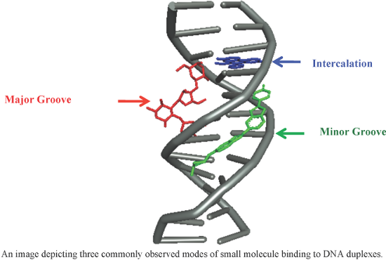
- absorption spectroscopy, viscosity measurement, cyclic voltammetry and molecular modeling (Figure 9) [93]. Docking results confirmed that these complexes have the ability to interact with the minor groove of the ct-DNA. In addition, the authors confirmed that in presence of ascorbic acid, these complexes

Graphical Abstract

Figure 1: A figure showing the hydrogen bonding patterns observed in (a) duplex (b) triplex and (c) quadruple...

Figure 2: (a) Portions of MATα1–MATα2 are shown contacting the minor groove of the DNA substrate. Key arginin...

Figure 3: Chemical structures of naturally occurring and synthetic hybrid minor groove binders.

Figure 4: Synthetic structural analogs of distamycin A by replacing one or more pyrrole rings with other hete...

Figure 5: Pictorial representation of the binding model of pyrrole–imidazole (Py/Im) polyamides based on the ...

Figure 6: Chemical structures of synthetic “hairpin” pyrrole–imidazole (Py/Im) conjugates.

Figure 7: (a) Minor groove complex formation between DNA duplex and 8-ring cyclic Py/Im polyamide (conjugate ...

Figure 8: Telomere-targeting tandem hairpin Py/Im polyamides 23 and 24 capable of recognizing >10 base pairs; ...

Figure 9: Representative examples of recently developed DNA minor groove binders.

Figure 10: Chemical structures of bisbenzamidazoles Hoechst 33258 and 33342 and their synthetic structural ana...

Figure 11: Chemical structures of bisamidines such as diminazene, DAPI, pentamidine and their synthetic struct...

Figure 12: Representative examples of recently developed bisamidine derivatives.

Figure 13: Chemical structures of chromomycin, mithramycin and their synthetic structural analogs 91 and 92.

Figure 14: Chemical structures of well-known naturally occurring DNA binding intercalators.

Figure 15: Naturally occurring indolocarbazole rebeccamycin and its synthetic analogs.

Figure 16: Representative examples of naturally occurring and synthetic derivatives of DNA intercalating agent...

Figure 17: Several recent synthetic varieties of DNA intercalators.

Figure 18: Aminoglycoside (neomycin)–Hoechst 33258/intercalator conjugates.

Figure 19: Chemical structures of triazole linked neomycin dimers and neomycin–bisbenzimidazole conjugates.

Figure 20: Representative examples of naturally occurring and synthetic analogs of DNA binding alkylating agen...

Figure 21: Chemical structures of naturally occurring and synthetic analogs of pyrrolobenzodiazepines.
Mechanochemistry of nucleosides, nucleotides and related materials
- Olga Eguaogie,
- Joseph S. Vyle,
- Patrick F. Conlon,
- Manuela A. Gîlea and
- Yipei Liang
Beilstein J. Org. Chem. 2018, 14, 955–970, doi:10.3762/bjoc.14.81

- POCl3 (e.g., Scheme 10), monoalkyl phosphorodichloridates or dialkyl phosphoromonochloridates in the absence of solvent has been reported [48]. Migaud and co-workers prepared highly water-sensitive phosphitylating agents directly from PCl3 in low viscosity ionic liquids derived from the tris

Graphical Abstract

Figure 1: Examples of equipment used to perform mechanochemistry on nucleoside and nucleotide substrates (not...

Figure 2: Ganciclovir.

Scheme 1: Nucleoside tritylation effected by hand grinding in a heated mortar and pestle.

Scheme 2: Persilylation of ribonucleoside hydroxy groups (and in situ acylation of cytidine) in a MBM.

Scheme 3: Nucleoside amine and carboxylic acid Boc protection using an improvised attritor-type mill.

Scheme 4: Nucleobase Boc protection via transient silylation using an improvised attritor-type mill.

Scheme 5: Chemoselective N-acylation of an aminonucleoside using LAG in a MBM.

Scheme 6: Azide–alkyne cycloaddition reactions performed in a copper vessel in a MBM.

Figure 3: a) Custom-machined copper vessel and zirconia balls used to perform CuAAC reactions (showing: upper...

Scheme 7: Thiolate displacement reactions of nucleoside derivatives in a MBM.

Scheme 8: Selenocyanate displacement reactions of nucleoside derivatives in a MBM.

Scheme 9: Nucleobase glycosidation reactions and subsequent deacetylation performed in a MBM.

Scheme 10: Regioselective phosphorylation of nicotinamide riboside in a MBM.

Scheme 11: Preparation of nucleoside phosphoramidites in a MBM using ionic liquid-stabilised chlorophosphorami...

Scheme 12: Preparation of a nucleoside phosphite triester using LAG in a MBM.

Scheme 13: Internucleoside phosphate coupling linkages in a MBM.

Scheme 14: Preparation of ADPR analogues using in a MBM.

Scheme 15: Synthesis of pyrophosphorothiolate-linked dinucleoside cap analogues in a MBM to effect hydrolytic ...

Figure 4: Early low temperature mechanised ball mill as described by Mudd et al. – adapted from reference [78].

Scheme 16: Co-crystal grinding of alkylated nucleobases in an amalgam mill (N.B. no frequency was recorded in ...

Figure 5: Materials used to prepare a smectic phase.

Figure 6: Structures of 5-fluorouracil (5FU) and nucleoside analogue prodrugs subject to mechanochemical co-c...

Scheme 17: Preparation of DNA-SWNT complex in a MBM.
Liquid-assisted grinding and ion pairing regulates percentage conversion and diastereoselectivity of the Wittig reaction under mechanochemical conditions
- Kendra Leahy Denlinger,
- Lianna Ortiz-Trankina,
- Preston Carr,
- Kingsley Benson,
- Daniel C. Waddell and
- James Mack
Beilstein J. Org. Chem. 2018, 14, 688–696, doi:10.3762/bjoc.14.57

- formation of this bond may have a large influence under mechanochemical conditions because there is not a solvent reservoir to accept the dispersion of these ions. Using Pearson’s hard and soft acid and base (HSAB) theory [29] and the Jones–Dole viscosity B coefficient [30] (Table 3), we can predict which
- alkali metal and halide pairs would be most favourable. For example, bromide is a borderline soft anion, so based on the proposed mechanism we would expect more product to form if the counter ion is Cs+(soft) than if it was Li+ (hard). Using the Jones–Dole viscosity B coefficient, we could also predict
- higher E selectivity was obtained. The high concentration of reactants under mechanochemical conditions allows for unique and potentially selective reactions that may not be achievable by traditional synthetic means. Further studies on the influence of HSAB theory and the Jones–Dole viscosity B

Graphical Abstract

Figure 1: Solution-based Wittig reaction mechanism.

Figure 2: 1H NMR spectra of stilbene mixture (a) and benzyl benzoate (b).

Scheme 1: Possible mechanism of benzyl benzoate formation.

Scheme 2: A possible mechanistic explanation for the E selectivity.

Scheme 3: Ball-milled Wittig reaction using excess benzaldehyde.

Figure 3: Comparison of solution based Wittig reaction (a) with polymer-supported mechanochemical Wittig reac...

Scheme 4: Stepwise ball-milled Wittig reaction with ethanol as the LAG solvent.

Scheme 5: Stepwise ball-milled Wittig reaction with ethanol evaporation between the steps.
5-Aminopyrazole as precursor in design and synthesis of fused pyrazoloazines
- Ranjana Aggarwal and
- Suresh Kumar
Beilstein J. Org. Chem. 2018, 14, 203–242, doi:10.3762/bjoc.14.15

- techniques like electronic spectra, viscosity measurement and thermal denaturation. Ahmetaj et al. [105] described a simple and efficient protocol for the synthesis of 7-heteroarylpyrazolo[1,5-a]pyrimidine-3-carboxamides 166 from the reaction of 5-aminopyrazole 161 with (E)-3-(dimethylamino)-1-(heteroaryl

Graphical Abstract

Figure 1: Selected examples of drugs with fused pyrazole rings.

Figure 2: Typical structures of some fused pyrazoloazines from 5-aminopyrazoles.

Scheme 1: Regiospecific synthesis of 4 and 6-trifluoromethyl-1H-pyrazolo[3,4-b]pyridines.

Scheme 2: Synthesis of pyrazolo[3,4-b]pyridine-6-carboxylates.

Scheme 3: Synthesis of 1,4,6-triaryl-1H-pyrazolo[3,4-b]pyridines with ionic liquid .

Scheme 4: Synthesis of coumarin-based isomeric tetracyclic pyrazolo[3,4-b]pyridines.

Scheme 5: Synthesis of 6-substituted pyrazolo[3,4-b]pyridines under Heck conditions.

Scheme 6: Microwave-assisted palladium-catalyzed synthesis of pyrazolo[3,4-b]pyridines.

Scheme 7: Acid-catalyzed synthesis of pyrazolo[3,4-b]pyridines via enaminones.

Scheme 8: Synthesis of pyrazolo[3,4-b]pyridines via aza-Diels–Alder reaction.

Scheme 9: Synthesis of macrocyclane fused pyrazolo[3,4-b]pyridine derivatives.

Scheme 10: Three-component synthesis of 4,7-dihydro-1H-pyrazolo[3,4-b]pyridine derivatives.

Scheme 11: Ultrasonicated synthesis of spiro[indoline-3,4'-pyrazolo[3,4-b]pyridine]-2,6'(1'H)-diones.

Scheme 12: Synthesis of spiro[indoline-3,4'-pyrazolo[3,4-b]pyridine] derivatives under conventional heating co...

Scheme 13: Nanoparticle-catalyzed synthesis of pyrazolo[3,4-b]pyridine-spiroindolinones.

Scheme 14: Microwave-assisted multicomponent synthesis of spiropyrazolo[3,4-b]pyridines.

Scheme 15: Unexpected synthesis of naphthoic acid-substituted pyrazolo[3,4-b]pyridines.

Scheme 16: Multicomponent synthesis of variously substituted pyrazolo[3,4-b]pyridine derivatives.

Scheme 17: Three-component synthesis of 4,7-dihydropyrazolo[3,4-b]pyridines and pyrazolo[3,4-b]pyridines.

Scheme 18: Synthesis of pyrazolo[3,4-b]pyridine-5-spirocycloalkanediones.

Scheme 19: Ultrasound-mediated three-component synthesis of pyrazolo[3,4-b]pyridines.

Scheme 20: Multicomponent synthesis of 4-aryl-3-methyl-1-phenyl-4,6,8,9-tetrahydropyrazolo [3,4-b]thiopyrano[4...

Scheme 21: Synthesis of 2,3-dihydrochromeno[4,3-d]pyrazolo[3,4-b]pyridine-1,6-diones.

Scheme 22: FeCl3-catalyzed synthesis of o-hydroxyphenylpyrazolo[3,4-b]pyridine derivatives.

Scheme 23: Ionic liquid-mediated synthesis of pyrazolo[3,4-b]pyridines.

Scheme 24: Microwave-assisted synthesis of pyrazolo[3,4-b]pyridines.

Scheme 25: Multicomponent synthesis of pyrazolo[3,4-b]pyridine-5-carbonitriles.

Scheme 26: Unusual domino synthesis of 4,7-dihydropyrazolo[3,4-b]pyridine-5-nitriles.

Scheme 27: Synthesis of 4,5,6,7-tetrahydro-4H-pyrazolo[3,4-b]pyridines under conventional heating and ultrasou...

Scheme 28: L-Proline-catalyzed synthesis of of pyrazolo[3,4-b]pyridine.

Scheme 29: Microwave-assisted synthesis of 5-aminoarylpyrazolo[3,4-b]pyridines.

Scheme 30: Microwave-assisted multi-component synthesis of pyrazolo[3,4-e]indolizines.

Scheme 31: Synthesis of fluoropropynyl and fluoroalkyl substituted pyrazolo[1,5-a]pyrimidine.

Scheme 32: Acid-catalyzed synthesis of pyrazolo[1,5-a]pyrimidine derivatives.

Scheme 33: Chemoselective and regiospecific synthesis of 2-(3-methylpyrazol-1’-yl)-5-methylpyrazolo[1,5-a]pyri...

Scheme 34: Regioselective synthesis of 7-trifluoromethylpyrazolo[1,5-a]pyrimidines.

Scheme 35: Microwave-assisted synthesis of 7-trifluoromethylpyrazolo[1,5-a]pyrimidine carboxylates.

Scheme 36: Microwave and ultrasound-assisted synthesis of 7-trifluoromethylpyrazolo[1,5-a]pyrimidines.

Scheme 37: Base-catalyzed unprecedented synthesis of pyrazolo[1,5-a]pyrimidines via C–C bond cleavage.

Scheme 38: Synthesis of aminobenzothiazole/piperazine linked pyrazolo[1,5-a]pyrimidines.

Scheme 39: Synthesis of aminoalkylpyrazolo[1,5-a]pyrimidine-7-amines.

Scheme 40: Synthesis of pyrazolo[1,5-a]pyrimidines from condensation of 5-aminopyrazole 126 and ethyl acetoace...

Scheme 41: Synthesis of 7-aminopyrazolo[1,5-a]pyrimidines.

Scheme 42: Unexpected synthesis of 7-aminopyrazolo[1,5-a]pyrimidines under solvent free and solvent-mediated c...

Scheme 43: Synthesis of N-(4-aminophenyl)-7-aryloxypyrazolo[1,5-a]pyrimidin-5-amines.

Scheme 44: Base-catalyzed synthesis of 5,7-diarylpyrazolo[1,5-a]pyrimidines.

Scheme 45: Synthesis of 6,7-dihydropyrazolo[1,5-a]pyrimidines in PEG-400.

Scheme 46: Synthesis of 7-heteroarylpyrazolo[1,5-a]pyrimidine-3-carboxamides.

Scheme 47: Synthesis of 7-heteroarylpyrazolo[1,5-a]pyrimidine derivatives under conventional heating and micro...

Scheme 48: Synthesis of N-aroylpyrazolo[1,5-a]pyrimidine-5-amines.

Scheme 49: Regioselective synthesis of ethyl pyrazolo[1,5-a]pyrimidine-7-carboxylate.

Scheme 50: Sodium methoxide-catalyzed synthesis of 3-cyano-6,7-diarylpyrazolo[1,5-a]pyrimidines.

Scheme 51: Synthesis of various pyrazolo[3,4-d]pyrimidine derivatives.

Scheme 52: Synthesis of hydrazinopyrazolo[3,4-d]pyrimidine derivatives.

Scheme 53: Synthesis of N-arylidinepyrazolo[3,4-d]pyrimidin-5-amines.

Scheme 54: Synthesis of pyrazolo[3,4-d]pyrimidinyl-4-amines.

Scheme 55: Iodine-catalyzed synthesis of pyrazolo[3,4-d]pyrimidinones.

Scheme 56: Synthesis of ethyl 6-amino-2H-pyrazolo[3,4-d]pyrimidine-4-carboxylate.

Scheme 57: Synthesis of 4-substituted-(3,6-dihydropyran-4-yl)-1H-pyrazolo[3,4-d]pyrimidines.

Scheme 58: Synthesis of 1-(2,4-dichlorophenyl)pyrazolo[3,4-d]pyrimidin-4-yl carboxamides.

Scheme 59: Synthesis of 5-(1,3,4-thidiazol-2-yl)pyrazolo[3,4-d]pyrimidine.

Scheme 60: One pot POCl3-catalyzed synthesis of 1-arylpyrazolo[3,4-d]pyrimidin-4-ones.

Scheme 61: Synthesis of 4-amino-N1,C3-dialkylpyrazolo[3,4-d]pyrimidines under Suzuki conditions.

Scheme 62: Microwave-assisted synthesis of pyrazolo[3,4-b]pyrazines.

Scheme 63: Synthesis and derivatization of pyrazolo[3,4-b]pyrazine-5-carbonitriles.

Scheme 64: Synthesis of 2-thioxo-pyrazolo[1,5-a][1,3,5]triazin-4-ones.

Scheme 65: Synthesis of 2,3-dihydropyrazolo[1,5-a][1,3,5]triazin-4(1H)-one.

Scheme 66: Synthesis of pyrazolo[1,5-a][1,3,5]triazine-8-carboxylic acid ethyl ester.

Scheme 67: Microwave-assisted synthesis of 4,7-dihetarylpyrazolo[1,5-a][1,3,5]triazines.

Scheme 68: Alternative synthetic route to 4,7-diheteroarylpyrazolo[1,5-a][1,3,5]triazines.

Scheme 69: Synthesis of 4-aryl-2-ethylthio-7-methylpyrazolo[1,5-a][1,3,5]triazines.

Scheme 70: Microwave-assisted synthesis of 4-aminopyrazolo[1,5-a][1,3,5]triazine.

Scheme 71: Synthesis of pyrazolo[3,4-d][1,2,3]triazines from pyrazol-5-yl diazonium salts.

Scheme 72: Synthesis of 2,5-dihydropyrazolo[3,4-e][1,2,4]triazines.

Scheme 73: Synthesis of pyrazolo[5,1-c][1,2,4]triazines via diazopyrazolylenaminones.

Scheme 74: Synthesis of pyrazolo[5,1-c][1,2,4]triazines in presence of sodium acetate.

Scheme 75: Synthesis of various 7-diazopyrazolo[5,1-c][1,2,4]triazine derivatives.

Scheme 76: One pot synthesis of pyrazolo[5,1-c][1,2,4]triazines.

Scheme 77: Synthesis of 4-amino-3,7,8-trinitropyrazolo-[5,1-c][1,2,4]triazines.

Scheme 78: Synthesis of tricyclic pyrazolo[5,1-c][1,2,4]triazines by azocoupling reaction.