


Abstract
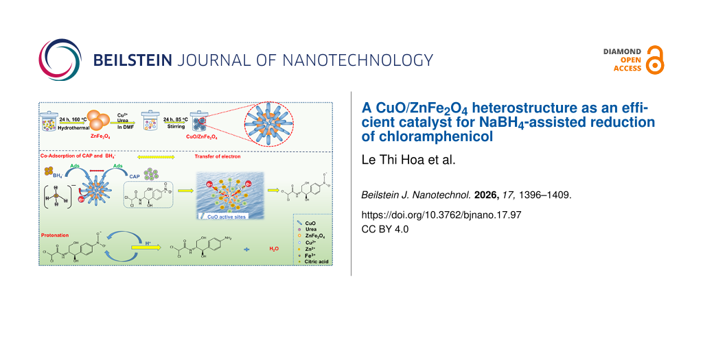
In this study, a CuO/ZnFe2O4 heterostructure in the form of a flower, consisting of rod-like surface features associated with CuO on ZnFe2O4 microspheres, was successfully synthesized and evaluated for its catalytic reduction of chloramphenicol (CAP) in the presence of NaBH4. Structural and morphological analysis confirmed the successful formation of the heterostructure with enhanced contact between ZnFe2O4 and CuO. Compared to pure ZnFe2O4, the CuO/ZnFe2O4 catalyst exhibited significantly improved catalytic activity for CAP reduction. Reaction conditions strongly influenced reduction efficiency, with optimal performance at pH 6, a catalyst dosage of 2.5 g·L−1, and a short reaction time of 20 min. The enhanced catalytic performance under mild, environmentally friendly conditions highlights CuO’s crucial role in promoting surface electron transfer and facilitating reduction. Kinetic analysis at room temperature indicated a change in apparent kinetic behavior during the reaction, with pseudo-first-order behavior in the initial stage and a tendency toward zeroth-order behavior at later times. This evolution is consistent with the involvement of surface-mediated catalytic processes. Overall, the CuO/ZnFe2O4 heterostructure shows significant potential as an efficient catalyst for rapid CAP reduction under near-neutral conditions, offering a promising strategy for wastewater treatment.
Introduction
The rapid expansion of agro-industrial sectors, including textile, chemical, fertilizer, pesticide, and pharmaceutical industries, has led to the continuous discharge of large amounts of organic pollutants into aquatic environments. Among these, antibiotic residues are of particular concern due to their persistence and resistance to conventional biological treatment processes. These compounds are often only partially removed, remaining either in treated effluents or temporarily retained in activated sludge, from which they can subsequently be released back into the environment [1]. Chloramphenicol (CAP), a broad-spectrum antibiotic effective against both Gram-positive and Gram-negative bacteria, has been widely used in medical and veterinary applications. However, its presence in water systems poses serious health risks, as CAP has been associated with severe toxic effects in humans, including bone marrow suppression and, in extreme cases, fatal aplastic anemia [2]. Therefore, the effective removal of these contaminants from water bodies is critical.
Various treatment technologies have been developed to address organic pollutants, including membrane separation, biodegradation, adsorption, and catalytic processes. Among these methods, catalytic reduction has attracted considerable attention due to its operational simplicity, cost-effectiveness, high efficiency, and ease of scaling from laboratory studies to practical applications. In recent years, organic pollutants containing nitro groups have received much attention in this field, as the nitro (–NO2) functional group can be selectively reduced to less toxic amino derivatives. In this context, sodium borohydride (NaBH4) has been widely used as a strong hydrogen donor for reduction conversions [3]. However, in the absence of a catalyst, the reduction process is kinetically unfavorable. Therefore, catalytic surfaces, especially those based on metal nanostructures or metal oxides, play a crucial role in facilitating electron transfer and enabling the efficient delivery of active hydrogen species from BH4− to pollutant molecules [4].
Magnetic nanoparticles (MNPs) are one of the magnetic metal nanoparticles widely used in catalysis for environmental treatment. MNPs can be synthesized with different compositions and phases, including pure metals such as Fe, Co, and Ni, metal oxides such as Fe3O4, γ-Fe2O3, ferrites such as MFe2O4 (M = Cu, Ni, Mn, Mg), and metal alloys such as FePt and CoPt [5]. Among them, ZnFe2O4 is considered a magnetic semiconductor that can act catalytically in the visible-light region because it has a narrow bandgap energy (Eg = 1.92 eV) with an electric potential (valence band (VB) at 0.38 V, and conduction band (CB) at −1.54 V) [6]. ZnFe2O4 has a spinel structure with Zn2+ occupying tetrahedral positions, and Fe3+ ions occupying octahedral positions in the crystal lattice. The exact distribution between cations at these two positions significantly impacts the electronic, magnetic, and catalytic properties of ZnFe2O4. In general, ZnFe2O4 has many outstanding characteristics, such as magnetism, optical properties, non-toxicity, and stability in many different environments [7]. However, at the nanoscale, ZnFe2O4 is often unstable due to its tendency to aggregate and undergo surface oxidation, which can reduce its dispersibility and magnetic performance over time. To overcome these limitations, various surface functionalization and structural modification strategies have been developed to improve stability and dispersibility, thereby enhancing catalytic efficiency. Based on these considerations, the development of efficient and stable catalysts based on ZnFe2O4 spinel ferrite coupled with transition-metal oxides is a potential approach to overcome existing limitations. Among the latter, CuO is a p-type semiconductor with a narrow bandgap (1.2–2.1 eV), high stability, good conductivity, low cost, and relatively low toxicity [8]; it has proven effective in applications such as energy storage, antimicrobial applications, and photocatalysis [9]. Therefore, the combination of ZnFe2O4 and CuO is expected to improve catalytic activity by enhancing surface reactivity and promoting electron transfer. In this study, a CuO/ZnFe2O4 heterostructure was designed and synthesized to enhance the catalytic reduction efficiency of CAP in the presence of NaBH4. The influence of key reaction parameters, including pH, catalyst dosage, and reaction time, was systematically investigated to evaluate the efficiency of treating nitro-containing organic compounds.
Experimental
Materials
Chloramphenicol (CAP, C11H12Cl2N2O5), ethylene glycol (C2H6O2), ZnCl2, FeCl3·6H2O, N,N′-dimethylformamide (DMF), CuCl2·2H2O, urea (CON2H4), NaCl, and citric acid (C6H8O7) were purchased from Merck (Germany). No additional purification was performed on the analytical reagents before use, and all experimental procedures used deionized water.
Synthesis of ZnFe2O4 NPs
ZnFe2O4 was synthesized by the hydrothermal method. A mixture of ethylene glycol (60 mL), ZnCl2 (0.28 g), FeCl3·6H2O (1.08 g), urea (2 g), and citric acid (0.5 g) was transferred to a 100 mL Teflon-lined stainless-steel autoclave and heated for 24 h at 160 °C. After cooling to room temperature, the resulting solid was filtered, washed with deionized water, and dried in an oven for 6 h at 60 °C. The resulting solid was transferred to a muffle furnace at 400 °C for 2 h, and the sample was further washed and dried for 6 h at 60 °C [10].
Synthesis of CuO/ZnFe2O4
ZnFe2O4 (600 mg) was added to a solution containing CuCl2·2H2O (540 mg) and urea (1.0 g) dissolved in DMF (60 mL). The mixture was homogenized using an ultrasonic device for 10 min. Then, this homogeneous solution was transferred to a heat-resistant vessel in an autoclave and heated at 85 °C for 24 h. The product collected by centrifugation (10,000 rpm, 5 min) was washed with DMF and acetone several times. Finally, CuO/ZnFe2O4 was dried overnight at room temperature.
Characterization
The crystal structure of the composite materials was analyzed by X-ray diffraction (XRD; Bruker AXS, Germany) using Cu Kα radiation (λ = 1.5406 Å) over the 2θ range of 10–80°. Before analysis, the powder samples were lightly ground and spread evenly on a sample holder to ensure a flat and uniform surface. Surface morphology and microstructure of the samples were examined by scanning electron microscopy (SEM, Hitachi S-4800, Japan). The surface chemical composition and elemental state were studied using X-ray photoelectron spectroscopy (XPS; K-Alpha, Thermo VG, United Kingdom) with monochromated Al Kα radiation as the excitation source. Nitrogen adsorption measurements were performed to evaluate the textural properties of ZnFe2O4 and CuO/ZnFe2O4. We calculated the specific surface area using the Brunauer–Emmett–Teller (BET) method and evaluated pore volume and pore width from the adsorption data, including the Barrett–Joyner–Halenda (BJH) analysis.
Catalytic experiments
In the catalytic reduction experiment, 40 mL of CAP solution (30 mg·L−1) at a set pH was mixed with a specified amount of catalyst. Next, 5 mL of NaBH4 solution (60 mM) was added, and distilled water was added to reach a total volume of 100 mL. Consequently, the initial CAP concentration (C₀) in the reaction system was 12 mg·L−1, while the NaBH4 concentration was 3 mM. The mixture was stirred at 150 rpm. After every 2 min, the solids were magnetically separated, and 2.5 mL of supernatant was collected for CAP concentration measurement. The removal efficiency was evaluated using the ratio C/C0, decreasing from 1 to 0 as efficiency increased. The effects of time (5–50 min), pH (4–10), catalyst dosage (2.0, 2.5, and 3.0 g·L−1), and ionic strength with NaCl concentration (0.1–0.4 M), on removal efficiency were systematically studied to find optimal conditions. All catalytic reduction experiments were conducted under normal laboratory ambient light without light shielding. All experiments were performed under identical ambient-light conditions and with identical reaction-vessel configurations to ensure consistency.
The simulated wastewater matrix was prepared using representative inorganic ions and natural organic matter, as commonly included in synthetic wastewater formulations in previous studies [11,12]. The matrix comprised CAP (12 mg·L−1), NaCl (25 mg·L−1), NaHCO3 (40 mg·L−1), Na2SO4 (25 mg·L−1), NaH2PO4·H2O (7 mg·L−1), and sodium humate (2 mg·L−1). These constituents were chosen to reflect the typical levels of chloride, bicarbonate, sulfate, phosphate, and dissolved organic matter found in complex wastewater matrices. The CuO/ZnFe2O4 catalyst and NaBH4 were then introduced under the same conditions used in the catalytic reduction experiments.
For the recycling experiments, the CuO/ZnFe2O4 catalyst was magnetically recovered after each catalytic cycle, washed with deionized water, dried, and reused under the same reaction conditions for five consecutive cycles. After each cycle, the separated liquid phase was analyzed by atomic absorption spectroscopy (AAS) to determine the concentrations of dissolved Fe, Cu, and Zn. We further characterized the catalyst recovered after the fifth cycle by XRD and XPS.
Results and Discussion
Characterization
Crystal structure and phase composition of ZnFe2O4 and CuO/ZnFe2O4 were studied by X-ray diffraction (XRD). As shown in Figure 1, the diffraction peaks of pure ZnFe2O4 located at 2θ = 29.9°, 35.2°, 42.9°, 53.8°, 57.0°, and 62.2° can be identified as the (220), (311), (400), (422), (511), and (440) planes of cubic ZnFe2O4 spinel (PDF#22-1012), indicating the successful formation of well-crystallized ZnFe2O4 [13,14]. For the CuO/ZnFe2O4 composite material, all characteristic diffraction peaks of ZnFe2O4 appear, meaning the spinel structure of ZnFe2O4 remains intact after the formation of the composite material. Several new diffraction peaks appear at 2θ = 36.1°, 38.9°, 52.9°, 61.7°, and 66.2°, assigned to the planes (002), (111), (020), (113), and (311) of monoclinic CuO (PDF#48-1548), respectively [15,16]. The coexistence of ZnFe2O4 and CuO diffraction features confirms the successful construction of the CuO/ZnFe2O4 heterostructure, in which CuO is effectively incorporated without disrupting the ZnFe2O4 crystal framework.
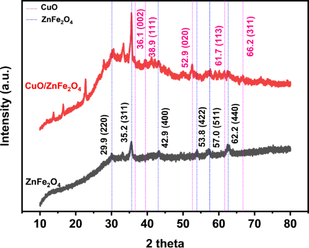
Figure 1: XRD patterns of ZnFe2O4 and CuO/ZnFe2O4.
Figure 1: XRD patterns of ZnFe2O4 and CuO/ZnFe2O4.
While XRD analysis confirmed the phase composition and crystal structure of the ZnFe2O4 and CuO/ZnFe2O4 samples, XPS analysis clarified the surface elemental composition, chemical states, and electronic interactions at the interface between ZnFe2O4 and CuO. The survey XPS spectra of ZnFe2O4 and CuO/ZnFe2O4 (Figure 2a) show Zn, Fe, and O in pristine ZnFe2O4 and, additionally, a clear Cu signal in the heterostructure, confirming the surface incorporation of the Cu-containing component. The high-resolution Zn 2p spectra (Figure 2b) exhibit Zn 2p3/2 and Zn 2p1/2 components at approximately 1021 and 1044 eV, respectively, consistent with Zn2+ in the spinel ferrite structure [17,18]. The Fe 2p spectra were re-evaluated by considering the characteristic multiplet and shake-up satellite structure of Fe in iron oxides rather than assigning a single unconstrained peak to each formal oxidation state. For ZnFe2O4, the Fe 2p3/2 and Fe 2p1/2 envelopes occur at approximately 710.84 and 724.18 eV, together with satellite features at approximately 718.58 and 732.20 eV (Figure 2c). In CuO/ZnFe2O4, the corresponding Fe 2p features remain in the Fe(III)-characteristic binding-energy region, with a satellite near 718.81 eV. These spectral features indicate that Fe(III) is the predominant iron oxidation state, consistent with the Zn2+Fe23+O4 spinel structure identified independently by XRD. No distinct additional Fe(I) or Fe(II) components could be reliably resolved from the experimental spectra; therefore, such components were not artificially introduced into the fitting. For Cu 2p (Figure 2d), the main Cu 2p3/2 and Cu 2p1/2 peaks are located at 933.25 and 953.14 eV, respectively, with a spin–orbit separation of approximately 19.9 eV. Pronounced shake-up satellite features at approximately 941.92 and 961.83 eV are characteristic of Cu(II) and support CuO as the predominant Cu-containing phase, in agreement with XRD [19]. Accordingly, the Cu 2p analysis was assigned to the experimentally resolved Cu(II) doublet and its characteristic shake-up satellite contributions. Distinct Cu(I) or Cu(III) components were not resolved and were therefore not introduced artificially into the deconvolution. The O 1s spectra (Figure 2e) were interpreted according to oxygen chemical environments rather than formal metal oxidation states. In ZnFe2O4, the lower-binding-energy contribution at approximately 529.28 eV is assigned primarily to lattice O2− in metal–oxygen bonds, whereas the higher-binding-energy contribution near 530.94 eV is associated with surface/defect-related and hydroxy/adsorbed oxygen species [17]. In the CuO/ZnFe2O4 heterostructure, the broadened O 1s envelope reflects overlapping oxygen environments associated with the ZnFe2O4 and CuO lattices and surface-related oxygen species. Because these contributions overlap strongly, the O 1s spectrum is discussed in terms of chemically plausible oxygen environments without overassigning individual components. Overall, the revised XPS analysis supports Zn2+, predominantly Fe3+, and predominantly Cu2+ as the resolved cationic states in the CuO/ZnFe2O4 heterostructure, consistent with the ZnFe2O4 and CuO phases independently identified by [17-22].
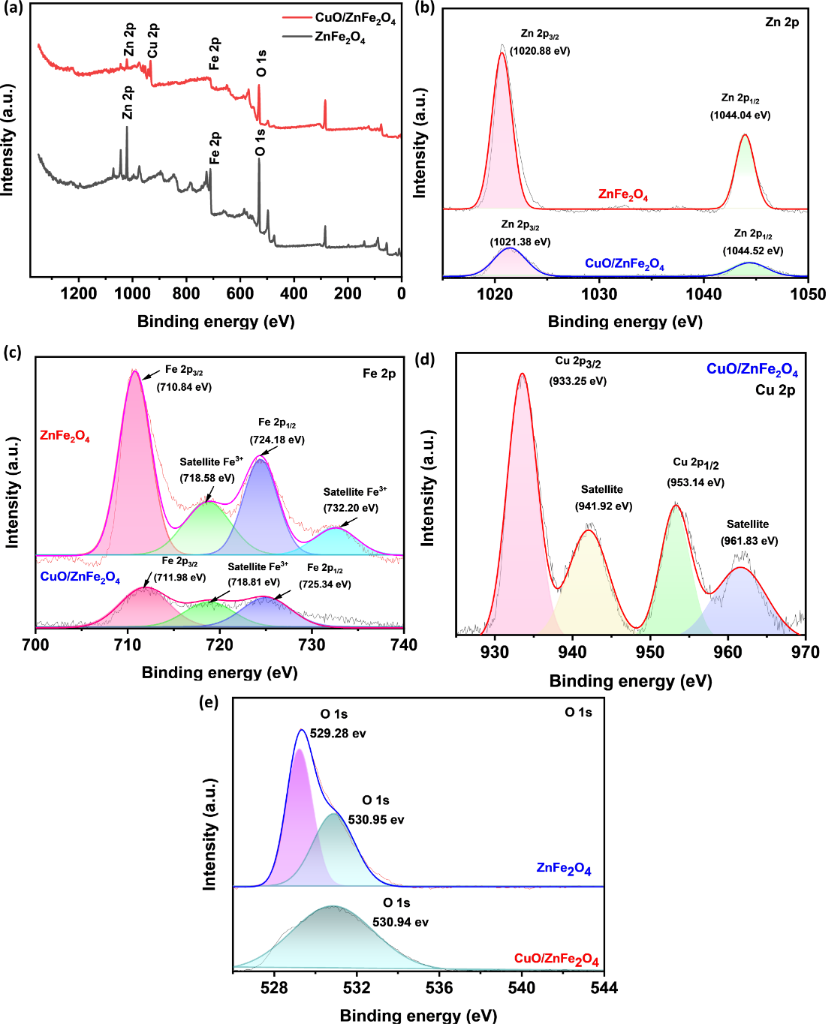
Figure 2: XPS spectra. (a) Survey spectrum, (b) Zn 2p and (c) Fe 2p for ZnFe2O4 and CuO/ZnFe2O4, (d) Cu 2p for CuO/ZnFe2O4 and (e) O 1s for ZnFe2O4 and CuO/ZnFe2O4.
Figure 2: XPS spectra. (a) Survey spectrum, (b) Zn 2p and (c) Fe 2p for ZnFe2O4 and CuO/ZnFe2O4, (d) Cu 2p fo...
N2 adsorption measurements were performed to assess the textural properties of ZnFe2O4 and CuO/ZnFe2O4. The BET specific surface area decreased from 56.89 m2·g−1 for ZnFe2O4 to 49.27 m2·g−1 for CuO/ZnFe2O4, showing that CuO incorporation did not enlarge the specific surface area. In contrast, the total pore volume increased from 0.1653 to 0.1825 cm3·g−1, while the average pore width (4V/A by BET) increased from 11.62 to 14.82 nm. The BJH adsorption average pore width likewise increased from 11.06 to 13.45 nm. These results indicate that CuO incorporation modifies the pore architecture of ZnFe2O4 rather than simply increasing its specific surface area. The moderate decrease in BET surface area may be associated with partial coverage or blockage of accessible ZnFe2O4 surface sites by the deposited CuO component, whereas the increased pore volume and average pore width suggest larger accessible pore/interparticle void dimensions in the heterostructure. While XPS provided strong evidence for the chemical states and confirmed the successful formation of the CuO/ZnFe2O4 composite, SEM was employed to further elucidate the surface morphology and assess the spatial distribution of the CuO phase on the ZnFe2O4 matrix. As illustrated in Figure 3, the CuO/ZnFe2O4 material exhibits flower-like hierarchical microstructures with characteristic dimensions of approximately 4 µm, as estimated from the SEM images. These structures are formed by the assembly of densely packed rod-like surface features radiating outward, resulting in a rough and highly textured morphology. Compared with ZnFe2O4 (inset), which displays a relatively compact, granular surface, the incorporation of CuO significantly alters the surface architecture, increasing surface roughness. Such hierarchical heterostructures are expected to provide more accessible active sites and facilitate interfacial electron transfer [23] during catalytic reaction.
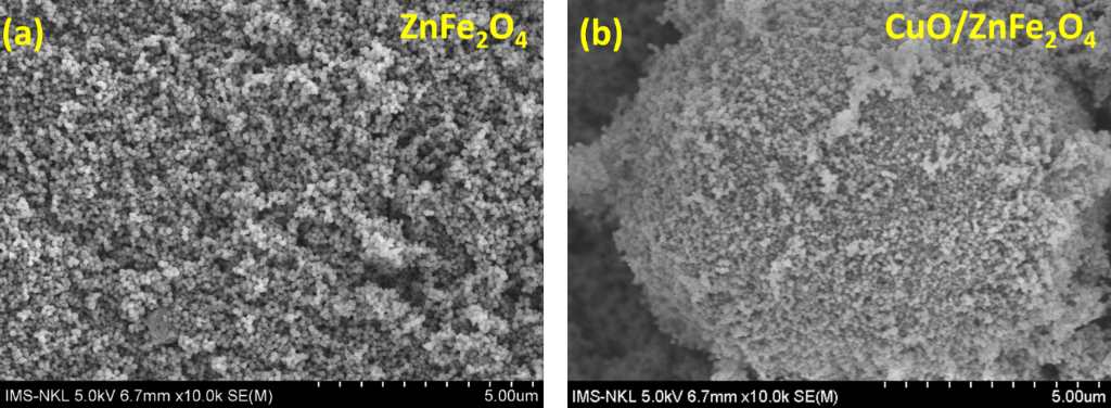
Figure 3: The SEM images of ZnFe2O4 (a) and CuO/ZnFe2O4 (b). The scale bar is 5 μm for both images.
Figure 3: The SEM images of ZnFe2O4 (a) and CuO/ZnFe2O4 (b). The scale bar is 5 μm for both images.
Catalytic activity
The catalytic reduction of CAP was examined using NaBH4 as the electron donor and both ZnFe2O4 and CuO/ZnFe2O4 as heterogeneous catalysts. The reaction progress was monitored by observing UV–vis spectral changes of CAP under various conditions: CAP alone, CAP with NaBH4, CAP with ZnFe2O4, CAP with CuO/ZnFe2O4, CAP with NaBH4 and ZnFe2O4, and CAP with NaBH4 and CuO/ZnFe2O4, as illustrated in Figure 4a. These control experiments were performed to assess the possible contribution of adsorption and to distinguish it from the NaBH4-assisted catalytic conversion of CAP. In the absence of NaBH4, the absorption intensity of CAP remained nearly constant in the presence of both ZnFe2O4 and CuO/ZnFe2O4, indicating that adsorption alone contributed minimally to CAP removal under the tested conditions. Similarly, NaBH4 alone did not significantly alter the absorption spectrum of CAP, demonstrating the kinetic limitation of direct reduction. When ZnFe2O4 was combined with NaBH4, only a slight decrease in CAP absorption intensity at approximately 280 nm was observed, without the emergence of a new absorption band, suggesting limited catalytic conversion. In contrast, the CuO/ZnFe2O4-NaBH4 system showed a substantial decrease in the characteristic CAP absorption band at approximately 280 nm, along with the appearance and growth of a new absorption feature at around 236 nm. These spectral changes suggest that the enhanced CAP removal in the CuO/ZnFe2O4-NaBH4 system is primarily due to catalytic transformation promoted by NaBH4, rather than adsorption. The improved catalytic performance is likely related to the incorporation of CuO, which may facilitate interfacial electron transfer and promote CAP conversion, while ZnFe2O4 provides a supporting surface and contributes to the overall catalytic process. Although the detailed reaction pathway remains to be elucidated, the comparative results in Figure 4a demonstrate that the CuO/ZnFe2O4 composite plays a more significant role in the NaBH4-assisted conversion of CAP than ZnFe2O4 [24,25]. The kinetic change of the reduction process is more clearly shown in Figure 4b, which depicts the decrease in the absorption intensity of CAP at 280 nm over reaction time after the addition of CuO/ZnFe2O4 in the presence of NaBH4. The absorption intensity decreases continuously throughout the reaction period, indicating that CAP is efficiently converted under these catalytic conditions. These results confirm that the CuO/ZnFe2O4 system exhibits superior catalytic activity compared to ZnFe2O4 alone and highlight the role of CuO in enhancing the CAP reduction efficiency in the NaBH4 system.
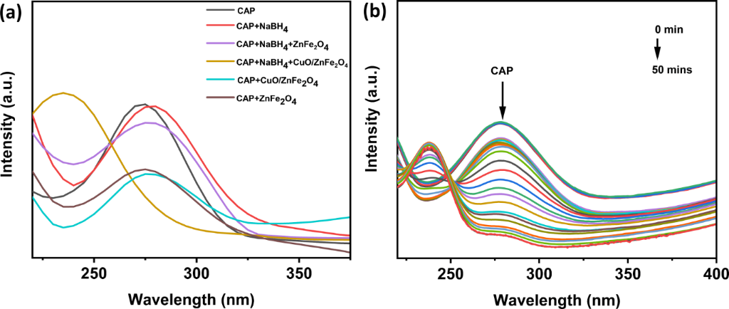
Figure 4: UV–vis spectra of the CAP solution before and after the removal processes (a) all samples; (b) CuO/ZnFe2O4 over 50 min of reaction time.
Figure 4: UV–vis spectra of the CAP solution before and after the removal processes (a) all samples; (b) CuO/...
The results of the pH effect survey (Figure 5) show that catalytic reduction activity strongly depends on the reaction environment and the material’s surface. For ZnFe2O4, the absorption spectrum changed only slightly over time within the investigated pH range (pH 4, 6, and 10), indicating limited CAP removal under these conditions. Together with the control experiments in Figure 4a, which showed minimal adsorption in the absence of NaBH4, these results indicate that pristine ZnFe2O4 exhibits limited catalytic activity in the NaBH4-assisted system compared with the CuO/ZnFe2O4 heterostructure [26]. Conversely, the CuO/ZnFe2O4 system exhibits a significant pH dependence, with the highest catalytic performance observed at pH 6. Under this condition, the C/C₀ ratio decreases markedly, indicating rapid CAP conversion. The enhanced activity near pH 6 may reflect a favorable balance between catalyst surface charge, CAP–surface interactions, and the availability of BH4−-derived reducing species, thereby facilitating interfacial electron transfer [27]. At more acidic or alkaline pH, less favorable surface interactions may reduce the catalytic performance. Furthermore, the incorporation of CuO provides redox-active surface sites that may facilitate electron transfer [28], which may explain the enhanced catalytic performance of CuO/ZnFe2O4 compared with ZnFe2O4.
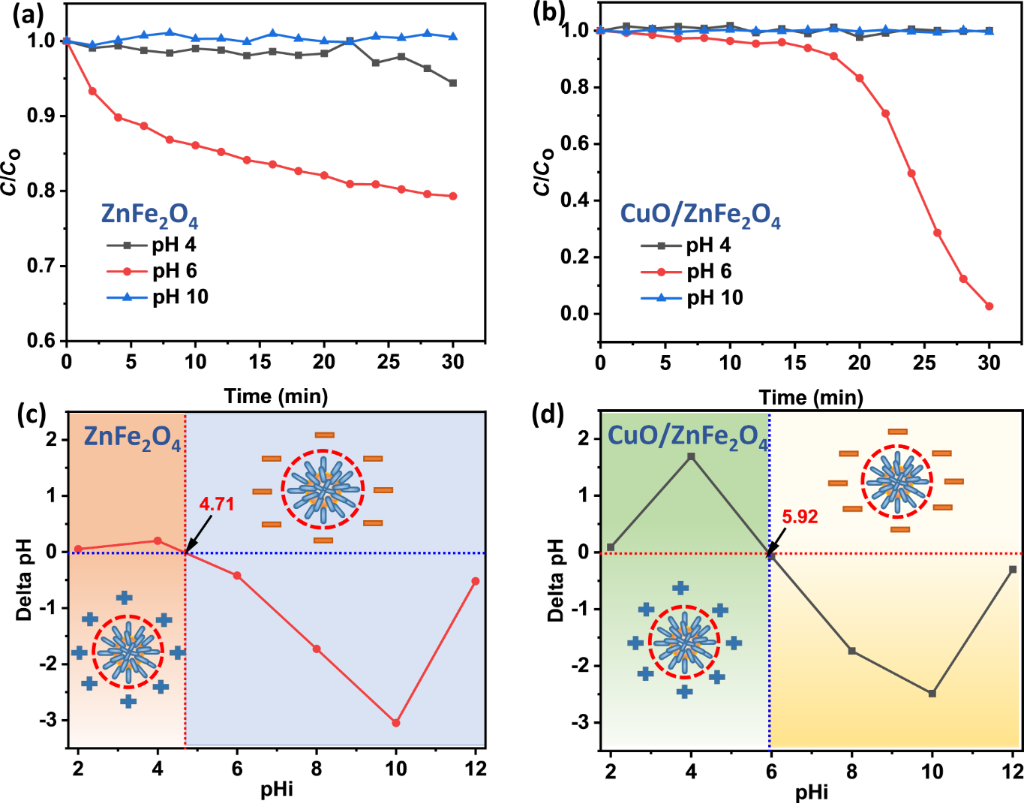
Figure 5: (a, b) Effect of pH on the reduction of CAP; pHPZC of (c) ZnFe2O4 and (d) CuO/ZnFe2O4.
Figure 5: (a, b) Effect of pH on the reduction of CAP; pHPZC of (c) ZnFe2O4 and (d) CuO/ZnFe2O4.
Figure 6 illustrates the effect of catalyst dosage (2.0, 2.5, and 3.0 g·L−1) on the catalytic removal efficiency of CAP in the presence of NaBH4. Compared with the dosage of 2.0 g·L−1, increasing the CuO/ZnFe2O4 loading to 2.5 and 3.0 g·L−1 significantly enhanced both the removal efficiency and the reaction rate throughout the catalytic process. Specifically, the system containing 2.0 g·L−1 of catalyst required approximately 30 min to achieve high CAP removal efficiency, whereas the reaction time was shortened to 20 min and 22 min for catalyst dosages of 2.5 and 3.0 g·L−1, respectively. The improved catalytic performance at higher catalyst loadings can be attributed primarily to the increased availability of CuO-containing active sites, which facilitate interactions among BH4−, CAP, and the catalyst surface and promote interfacial electron transfer [28]. However, when the catalyst dosage exceeded 2.5 g·L−1, the catalytic activity enhancement became insignificant and even declined slightly. This behavior is likely associated with the limited amount of NaBH4 in the reaction system, which restricts the generation of active hydrogen species and the transfer of electrons required for the reduction reaction [29]. Therefore, a catalyst dosage of 2.5 g·L−1 was selected as the optimal condition for subsequent experiments.
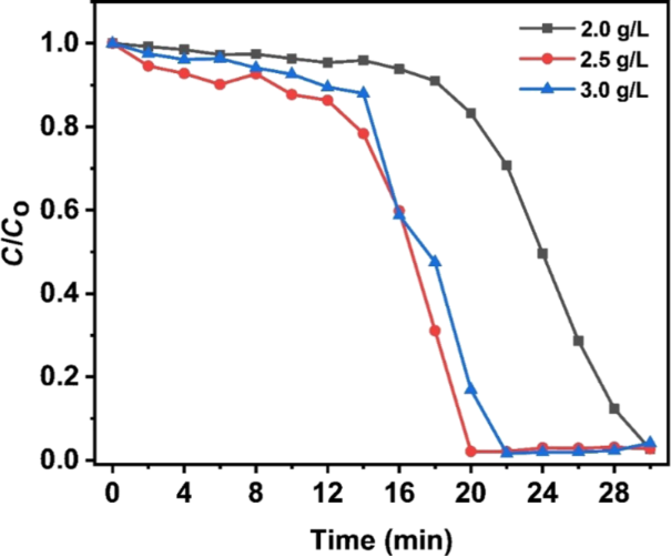
Figure 6: Effect of catalyst dosage on the catalytic reduction of CAP using CuO/ZnFe2O4 at catalyst dosages of 2.0, 2.5, and 3.0 g·L−1.
Figure 6: Effect of catalyst dosage on the catalytic reduction of CAP using CuO/ZnFe2O4 at catalyst dosages o...
Kinetic analysis results (Figure 7) at catalyst dosages of 2.0, 2.5, and 3.0 g·L−1 at room temperature indicate that the CAP reduction on CuO/ZnFe2O4 cannot be adequately interpreted as a single kinetic regime over the entire reaction period. The transition between the two apparent kinetic regions was assigned from the observed change in linearity of the kinetic profiles, which occurred after approximately 12–14 min. Accordingly, the 0–12 min interval was used to describe the initial apparent regime and the 14–22 min interval to evaluate the later regime. For 0–12 min, the ln(C/C₀) versus time plots showed good linearity with the pseudo-first-order model (Figure 7a,c,e). At later times, the profiles deviated from the initial pseudo-first-order behavior and showed a tendency toward zeroth-order behavior (Figure 7b,d,f). These kinetic assignments should therefore be regarded as apparent descriptions of different portions of the reaction profile rather than as proof of a sharp mechanistic transition at a single time point. The apparent rate constants also showed a non-monotonic dependence on catalyst dosage. In particular, k1 decreased from 0.01106 min−1 at 2.5 g·L−1 to 0.00805 min−1 at 3.0 g·L−1, whereas the later-stage k₀ increased from 0.2627 to 0.3218 mg·L−1·min−1. This difference is not a direct contradiction because k1 and k₀ describe different apparent kinetic regions and have different dimensions; they should therefore not be compared as a single dose-dependent rate parameter. The results instead indicate that increasing the nominal catalyst dosage beyond 2.5 g·L−1 does not produce a proportional improvement in the apparent reaction rate in all stages of the process, consistent with the small decrease in overall catalytic performance observed at 3.0 g·L−1. The kinetic profiles presented here were obtained from individual experimental runs rather than replicate kinetic measurements; therefore, statistically meaningful standard deviations and error bars cannot be calculated retrospectively. The kinetic interpretation is consequently limited to the measured profiles and their apparent fitting behavior, without assigning statistical significance to differences between fitted parameters. The observed evolution in kinetic behavior may reflect changes in surface coverage by CAP, reaction intermediates, BH4−-derived species, or borate products as the reaction proceeds. Such behavior is qualitatively consistent with a surface-mediated Langmuir–Hinshelwood-type process, but the present kinetic data alone do not establish a unique mechanistic model [30,31]. Among the investigated catalyst dosages, 2.5 g·L−1 provided the best overall CAP removal performance within 20 min and was therefore selected as the optimum dosage.
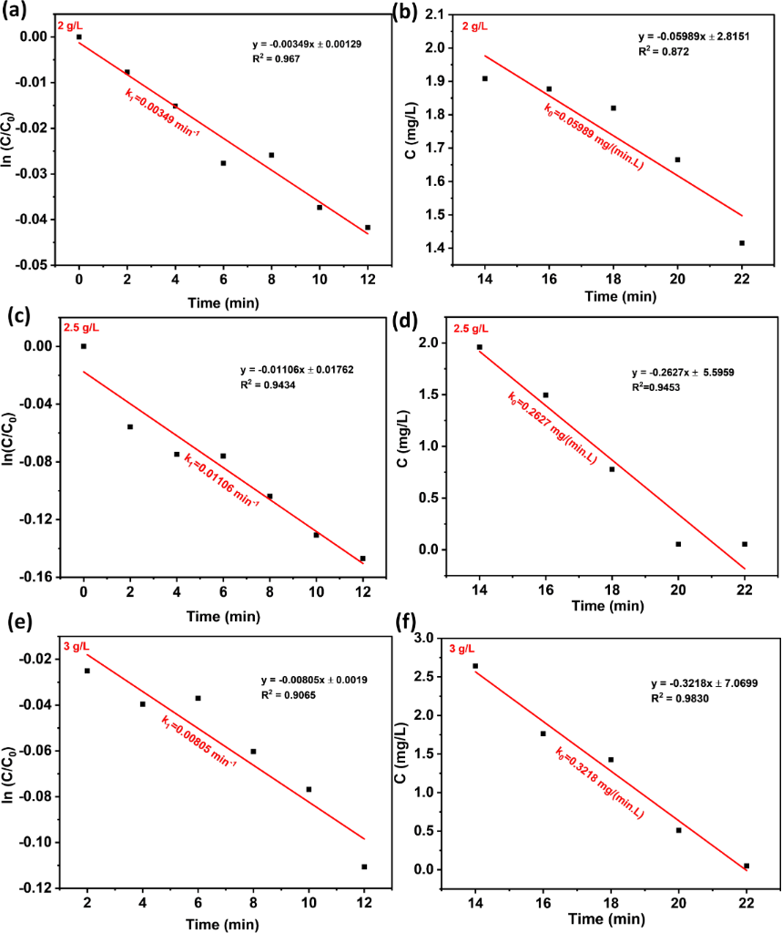
Figure 7: Kinetic analysis of CAP reduction of CuO/ZnFe2O4 at different dose of 2 g/L (a, b), 2.5 g/L (c, d) and 3 g/L (e, f) at room temperature.
Figure 7: Kinetic analysis of CAP reduction of CuO/ZnFe2O4 at different dose of 2 g/L (a, b), 2.5 g/L (c, d) ...
Different concentrations of NaCl were added to the CAP solution to evaluate the effect of ionic strength on the catalytic activity of CuO/ZnFe2O4. As shown in Figure 8a, both the decomposition efficiency and the rate of CAP reduction were strongly affected by ionic strength. As the NaCl concentration increased from 0.1 to 0.4 M, the reduction process became slower, requiring a longer reaction time to achieve equivalent removal efficiency. At relatively low ionic strengths, the electrolyte had only a minor effect on the catalytic reduction of CAP; however, a pronounced inhibitory effect was observed at higher ionic strengths, especially at 0.4 M. This phenomenon suggests that excess ions in solution may hinder the interaction among BH4−, CAP, and the CuO/ZnFe2O4 surface, thus inhibiting adsorption and electron transfer through the surface during catalysis, affecting catalytic efficiency [32]. Overall, these results indicate that the CuO/ZnFe2O4 heterostructure exhibits more favorable catalytic performance under conditions of low ionic strength. To further evaluate the performance of CuO/ZnFe2O4 in a more complex aqueous environment, a simulated wastewater system containing typical inorganic salts and sodium humate, as commonly used in synthetic wastewater formulations reported in previous studies [11,12], was investigated. Under simulated wastewater conditions, the CAP removal efficiency (Figure 8b) decreased relative to that observed in deionized water, yet remained notably high at 86.25%. The observed reduction aligns with the inhibitory trend observed in experiments on NaCl ionic strength (Figure 8a), although the current experiments could not isolate the individual contributions of each component in the simulated wastewater. Nevertheless, maintaining a CAP removal efficiency of 86.25% in the simulated wastewater environment demonstrates that the CuO/ZnFe2O4–NaBH4 system retains significant catalytic activity under more complex water conditions.
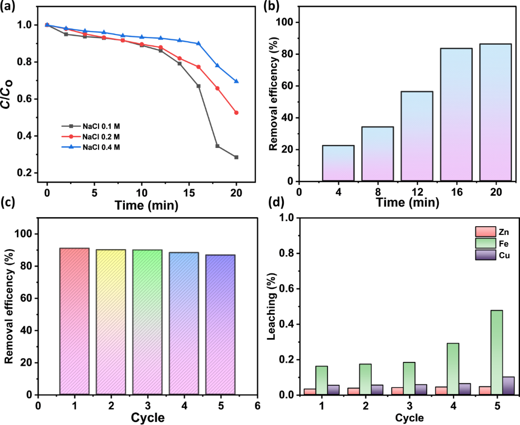
Figure 8: (a) Effect of ionic strength on CAP removal, (b) CAP removal efficiency in simulated wastewater, and (c) recyclability of CuO/ZnFe2O4 over five catalytic cycles.
Figure 8: (a) Effect of ionic strength on CAP removal, (b) CAP removal efficiency in simulated wastewater, an...
The reusability of the CuO/ZnFe2O4 catalyst for CAP reduction in the presence of NaBH4 was evaluated over five consecutive reaction cycles. As shown in Figure 8c, the CAP removal efficiency decreased only modestly from 91.0% in the first cycle to 86.8% after the fifth cycle, indicating that the catalyst retained substantial catalytic activity during repeated use. The modest performance loss may reflect a combination of catalyst loss during recovery, surface modification, accumulation of surface-bound species, and metal leaching during repeated operation. AAS analysis (Supporting Information File 1, Table S1) of the liquid phase after each catalytic cycle confirmed measurable Fe, Cu, and Zn leaching. These results indicate that, although the catalyst retains substantial catalytic activity over five cycles, metal release occurs under the investigated reaction conditions and limits the present catalyst system. To further assess the catalyst after repeated use, the material recovered after the fifth catalytic cycle was characterized by XRD and XPS (Figure 9).
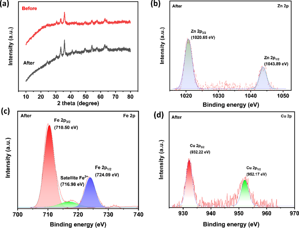
Figure 9: Post-reaction characterization of CuO/ZnFe2O4 recovered after five catalytic cycles: (a) XRD pattern, (b) Zn 2p, (c) Fe 2p, and (d) Cu 2p high-resolution XPS spectra.
Figure 9: Post-reaction characterization of CuO/ZnFe2O4 recovered after five catalytic cycles: (a) XRD patter...
After five consecutive catalytic cycles, the XRD pattern of the recovered catalyst still showed the main diffraction features of the CuO/ZnFe2O4 heterostructure (Figure 9a). This result indicates that the major crystalline framework remained detectable after repeated use. The XPS spectra taken after the reaction provided more information about the catalyst’s surface chemical states. The Zn 2p and Fe 2p signals remained (Figure 9b,c), indicating that Zn and Fe components persisted after five cycles. The Zn 2p3/2 and Zn 2p1/2 peaks were found at about 1020.65 and 1043.89 eV, and the Fe 2p3/2 and Fe 2p1/2 signals appear at approximately 710.50 and 724.09 eV, respectively, accompanied by an Fe(III)-related satellite peak at approximately 716.98 eV. In the Cu 2p region, the Cu 2p3/2 and Cu 2p1/2 peaks were seen at about 932.22 and 952.17 eV (Figure 9d). These lower Cu 2p binding energies match the presence of reduced Cu species on the catalyst surface after repeated exposure to NaBH4. However, because the Cu 2p binding-energy regions for Cu(I) and Cu(0) overlap, it is not possible to clearly identify the post-reaction Cu species as either Cu2O or metallic Cu based only on the Cu 2p spectrum. Overall, the XRD and XPS results after the reaction show that the main crystalline framework remains stable after five cycles, while the Cu-containing surface changes chemically under reaction conditions involving NaBH4. Together with AAS evidence of metal leaching, these results suggest that improving the structural and chemical stability of the CuO/ZnFe2O4 heterostructure, especially at the CuO-ZnFe2O4 interface, is an important area for future work.
According to Table 1, the CuO/ZnFe2O4 system achieves a significantly shorter reaction time of only 20 min, demonstrating rapid reduction under near-neutral conditions. Photocatalytic systems like Ce(MoO4)2/graphene oxide (GO) and Ag/TiO2 require longer reaction times and depend on external light irradiation. MOF-based (Al-MIL) and nano zero-valent iron (nZVI)/GO systems, though efficient, often need higher catalyst dosages or extended processing times. CuO/ZnFe2O4 stands out due to its fast kinetics, near-neutral pH operation, and operation without controlled external light irradiation, making it promising for practical NaBH4-assisted reduction. The initial CAP concentration of 12 mg·L−1 used in this study is much higher than that typically found in aquatic environments, where levels are typically in the nanogram per liter to low-microgram per liter range [33]. Therefore, further studies using environmentally relevant CAP concentrations are required to more comprehensively assess the practical applicability of the CuO/ ZnFe2O4 catalytic system.
Table 1: Comparison of CAP removal using different catalytic systems.
| Material | Conditions | Catalytic | Light source | Reference |
| Ce(MoO4)2/GO | pH 5; CCAP = 20 mg·L−1; t = 50 min | photocatalytic | visible | [34] |
| Ag/TiO2 | pH 6.5; CCAP = 20 mg·L−1; t = 120 min | photocatalytic | UV-C | [2] |
| persulfate | pH 3; CCAP = 0.03 mM; t = 120 min | UV-activated persulfate oxidation | UV | [35] |
| Al-MIL | pH 5.4; CCAP = 80 mg·L−1; t = 120 min | persulfate oxidation | – | [36] |
| nZVI/GO | pH 5; CCAP = 100 mg·L−1; t = 180 min | photocatalytic | – | [37] |
| CuO/ZnFe2O4 | pH 6; CCAP = 12 mg·L−1; t = 20 min | NaBH4 reduction | – | this study |
Mechanism
Previous studies have demonstrated that aromatic nitro compounds can be reduced to their corresponding amino derivatives using NaBH4 [38,39]. Based on these findings, Scheme 1 illustrates the proposed CAP reduction pathway on the CuO/ZnFe2O4 heterostructure. Initially, NaBH4 dissociates in aqueous solution to release BH4− ions, which may interact with the catalyst surface and facilitate electron transfer and the formation of reactive hydrogen species involved in CAP reduction. Simultaneously, CAP molecules are adsorbed onto the CuO/ZnFe2O4 surface, which could facilitate electron transfer between interfaces and subsequent reduction processes. As illustrated in Scheme 1, the nitro group of the CAP is proposed to undergo stepwise electron/proton transfer, leading to the formation of products consistent with the corresponding amino derivative (–NH2) and H2O.
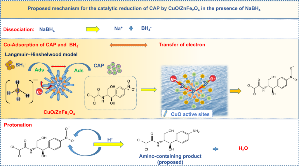
Scheme 1: Proposed mechanism of catalytic CAP reduction by CuO/ZnFe2O4 in the presence of NaBH4.
Scheme 1: Proposed mechanism of catalytic CAP reduction by CuO/ZnFe2O4 in the presence of NaBH4.
Kinetic analysis indicated pseudo-first-order behavior during the initial reaction stage and a tendency toward zeroth-order behavior at later times. This shift in apparent kinetics may reflect progressive changes in surface coverage by CAP, reaction intermediates, BH4−-derived species, or borate products. The observations are qualitatively consistent with a surface-mediated Langmuir–Hinshelwood-type process in which adsorption and interfacial electron transfer contribute to CAP reduction; however, the kinetic data alone do not establish a unique mechanistic pathway. Overall, the CuO/ZnFe2O4 heterostructure provides favorable interfacial sites for adsorption and electron transfer in the NaBH4-assisted catalytic system. The proposed pathway is consistent with previously reported catalytic reduction processes for nitro-containing organic compounds [40].
Conclusion
A CuO/ZnFe2O4 heterostructure was synthesized with a flower-like morphology composed of rod-like surface features associated with the CuO-containing component on the ZnFe2O4 surface. In the presence of NaBH4, the CuO/ZnFe2O4 system displayed markedly enhanced catalytic reduction efficiency for CAP compared to pristine ZnFe2O4, reaching maximum performance at pH 6, a catalyst loading of 2.5 g·L−1, and a reaction period of 20 min. The enhanced catalytic performance is attributed to the formation of the CuO/ZnFe2O4 heterostructure, which provides CuO-containing active sites and favorable interfacial interactions for reduction. Kinetic analysis indicated a change in apparent kinetic behavior during the reaction, with pseudo-first-order behavior in the initial stage and a tendency toward zeroth-order behavior at later times. This evolution is consistent with surface-mediated processes, although the present kinetic data do not establish a unique Langmuir–Hinshelwood mechanism. Reusability tests showed that CAP removal decreased only modestly from 91.0% in the first cycle to 86.8% after the fifth cycle. Post-reaction XRD showed that the major crystalline features of the heterostructure remained detectable after five cycles, while XPS indicated the presence of reduced Cu surface species, consistent with modification of the Cu-containing surface during repeated exposure to NaBH4. AAS analysis confirmed measurable Fe, Cu, and Zn leaching during repeated operation, identifying metal retention as a limitation of the present catalyst system. Overall, the CuO/ZnFe2O4 heterostructure demonstrates rapid NaBH4-assisted CAP reduction and substantial activity retention under simulated-wastewater and repeated-use conditions. Further development should focus on improving the heterostructure’s structural and chemical stability, particularly by strengthening the CuO–ZnFe2O4 interfacial interaction and suppressing metal leaching while preserving catalytic activity.
Supporting Information
| Supporting Information File 1: AAS measurements of dissolved metal ions. | ||
| Format: PDF | Size: 576.7 KB | Download |
Acknowledgements
The authors gratefully acknowledge IMS-NKL for assistance with SEM measurements and the facilities that supported XRD, XPS, and BET characterization in this study.
Data Availability Statement
Data generated and analyzed during this study is available from the corresponding author upon reasonable request.
References
-
Elmolla, E. S.; Chaudhuri, M. Desalination 2010, 252, 46–52. doi:10.1016/j.desal.2009.11.003
Return to citation in text: [1] -
Jodat, A.; Jodat, A. Desalin. Water Treat. 2014, 52, 2668–2677. doi:10.1080/19443994.2013.794115
Return to citation in text: [1] [2] -
Ravikumar, K. V. G.; Dubey, S.; Pulimi, M.; Chandrasekaran, N.; Mukherjee, A. J. Mol. Liq. 2016, 224, 589–598. doi:10.1016/j.molliq.2016.10.040
Return to citation in text: [1] -
Ecevit, H.; Altun, T. J. Water Process Eng. 2025, 76, 108177. doi:10.1016/j.jwpe.2025.108177
Return to citation in text: [1] -
Aghayi-Anaraki, M.; Safarifard, V. Eur. J. Inorg. Chem. 2020, 2020, 1916–1937. doi:10.1002/ejic.202000012
Return to citation in text: [1] -
Tao, R.; Zhao, C.; Shao, C.; Li, X.; Li, X.; Zhang, J.; Yang, S.; Liu, Y. Mater. Res. Bull. 2018, 104, 124–133. doi:10.1016/j.materresbull.2018.03.041
Return to citation in text: [1] -
Liu, Z.; Fan, T.; Zhou, H.; Zhang, D.; Gong, X.; Guo, Q.; Ogawa, H. Bioinspiration Biomimetics 2007, 2, 30–35. doi:10.1088/1748-3182/2/1/004
Return to citation in text: [1] -
Li, L.; Chen, X.; Quan, X.; Qiu, F.; Zhang, X. ACS Omega 2023, 8, 2723–2732. doi:10.1021/acsomega.2c07364
Return to citation in text: [1] -
Singh, J.; Soni, R. K. Appl. Surf. Sci. 2020, 521, 146420. doi:10.1016/j.apsusc.2020.146420
Return to citation in text: [1] -
Niaki, Z. M.; Ghorbani, M.; Ghoreishi, S. A. J. Environ. Health Sci. Eng. 2021, 19, 1583–1596. doi:10.1007/s40201-021-00713-x
Return to citation in text: [1] -
Zhao, Z.; Ma, X.; Wang, X.; Ma, Y.; Liu, C.; Hang, H.; Zhang, Y.; Du, Y.; Ye, W. Appl. Surf. Sci. 2018, 457, 1009–1017. doi:10.1016/j.apsusc.2018.06.285
Return to citation in text: [1] [2] -
Venancio, W. A. L.; Rodrigues-Silva, C.; Maniero, M. G.; Guimarães, J. R. Water Sci. Technol. 2018, 78, 1668–1678. doi:10.2166/wst.2018.443
Return to citation in text: [1] [2] -
Wang, K.; Chen, Q.; Xie, H.; Wang, M.; Kong, X.; Cheng, K.; Jin, Z. Catal. Lett. 2024, 154, 6227–6240. doi:10.1007/s10562-024-04830-8
Return to citation in text: [1] -
Huerta-Aguilar, C. A.; Diaz-Puerto, Z. J.; Tecuapa-Flores, E. D.; Thangarasu, P. ACS Omega 2022, 7, 33985–34001. doi:10.1021/acsomega.2c03153
Return to citation in text: [1] -
Wang, X.; Han, Q.; Cai, S.; Wang, T.; Qi, C.; Yang, R.; Wang, C. Analyst 2017, 142, 2500–2506. doi:10.1039/c7an00589j
Return to citation in text: [1] -
Zhu, D.; Wang, L.; Yu, W.; Xie, H. Sci. Rep. 2018, 8, 5282. doi:10.1038/s41598-018-23174-z
Return to citation in text: [1] -
Nikolic, M. V.; Vasiljevic, Z. Z.; Lukovic, M. D.; Pavlovic, V. P.; Krstic, J. B.; Vujancevic, J.; Tadic, N.; Vlahovic, B.; Pavlovic, V. B. Int. J. Appl. Ceram. Technol. 2019, 16, 981–993. doi:10.1111/ijac.13190
Return to citation in text: [1] [2] [3] -
Xu, Y.; Wu, S.; Li, X.; Huang, Y.; Wang, Z.; Han, Y.; Wu, J.; Meng, H.; Zhang, X. New J. Chem. 2017, 41, 15433–15438. doi:10.1039/c7nj03373g
Return to citation in text: [1] [2] -
Boruban, C.; Esenturk, E. N. J. Nanopart. Res. 2018, 20, 59. doi:10.1007/s11051-018-4139-0
Return to citation in text: [1] [2] -
Chen, H.; Liu, W.; Qin, Z. Catal. Sci. Technol. 2017, 7, 2236–2244. doi:10.1039/c7cy00308k
Return to citation in text: [1] -
Zhou, X.; Li, X.; Sun, H.; Sun, P.; Liang, X.; Liu, F.; Hu, X.; Lu, G. ACS Appl. Mater. Interfaces 2015, 7, 15414–15421. doi:10.1021/acsami.5b03537
Return to citation in text: [1] -
Thekkae Padil, V. V.; Černík, M. Int. J. Nanomed. 2013, 8, 889–898. doi:10.2147/ijn.s40599
Return to citation in text: [1] -
Solanki, K.; Sharma, S.; Yadav, S.; Kaushik, B.; Rana, P.; Dixit, R.; Sharma, R. K. Small 2023, 19, 2300394. doi:10.1002/smll.202300394
Return to citation in text: [1] -
Guo, W.; Zheng, Y.; Xiang, W.; Zhang, Y. RSC Sustainability 2025, 3, 243–254. doi:10.1039/d4su00531g
Return to citation in text: [1] -
Nachaichot, A.; Kenvised, O.; Choram, S.; Nijpanich, S.; Budsombat, S. RSC Adv. 2025, 15, 6974–6983. doi:10.1039/d5ra00081e
Return to citation in text: [1] -
Zhang, K.; Suh, J. M.; Choi, J.-W.; Jang, H. W.; Shokouhimehr, M.; Varma, R. S. ACS Omega 2019, 4, 483–495. doi:10.1021/acsomega.8b03051
Return to citation in text: [1] -
Mohd Din, A. T.; Ahmad, M. A.; Hameed, B. H. Chem. Eng. J. 2015, 260, 730–739. doi:10.1016/j.cej.2014.09.010
Return to citation in text: [1] -
Li, Y.; Wang, Y.; Lu, H.; Li, X. Int. J. Hydrogen Energy 2020, 45, 16080–16093. doi:10.1016/j.ijhydene.2020.04.002
Return to citation in text: [1] [2] -
Mirshafiee, F.; Rezaei, M. Sci. Rep. 2024, 14, 9659. doi:10.1038/s41598-024-60428-5
Return to citation in text: [1] -
Wunder, S.; Polzer, F.; Lu, Y.; Mei, Y.; Ballauff, M. J. Phys. Chem. C 2010, 114, 8814–8820. doi:10.1021/jp101125j
Return to citation in text: [1] -
Andrieux, J.; Demirci, U. B.; Miele, P. Catal. Today 2011, 170, 13–19. doi:10.1016/j.cattod.2011.01.019
Return to citation in text: [1] -
Kottappara, R.; Pillai, S. C.; Kizhakkekilikoodayil Vijayan, B. Inorg. Chem. Commun. 2020, 121, 108181. doi:10.1016/j.inoche.2020.108181
Return to citation in text: [1] -
Nguyen, L. M.; Nguyen, N. T. T.; Nguyen, T. T. T.; Nguyen, T. T.; Nguyen, D. T. C.; Tran, T. V. Environ. Chem. Lett. 2022, 20, 1929–1963. doi:10.1007/s10311-022-01416-x
Return to citation in text: [1] -
Karthik, R.; Vinoth Kumar, J.; Chen, S.-M.; Karuppiah, C.; Cheng, Y.-H.; Muthuraj, V. ACS Appl. Mater. Interfaces 2017, 9, 6547–6559. doi:10.1021/acsami.6b14242
Return to citation in text: [1] -
Tan, C.; Fu, D.; Gao, N.; Qin, Q.; Xu, Y.; Xiang, H. J. Photochem. Photobiol., A 2017, 332, 406–412. doi:10.1016/j.jphotochem.2016.09.021
Return to citation in text: [1] -
Geçgel, C.; Görmez, Ö.; Gözmen, B.; Turabik, M.; Kalderis, D. Chemosphere 2022, 308, 136411. doi:10.1016/j.chemosphere.2022.136411
Return to citation in text: [1] -
Idham, M. F.; Falyouna, O.; Eljamal, R.; Maamoun, I.; Eljamal, O. J. Water Process Eng. 2022, 50, 103289. doi:10.1016/j.jwpe.2022.103289
Return to citation in text: [1] -
Colón, D.; Weber, E. J.; Anderson, J. L.; Winget, P.; Suárez, L. A. Environ. Sci. Technol. 2006, 40, 4449–4454. doi:10.1021/es0600429
Return to citation in text: [1] -
Zeynizadeh, B.; Mohammadzadeh, I.; Shokri, Z.; Ali Hosseini, S. J. Colloid Interface Sci. 2017, 500, 285–293. doi:10.1016/j.jcis.2017.03.030
Return to citation in text: [1] -
Edebali, S. Appl. Surf. Sci. Adv. 2023, 18, 100496. doi:10.1016/j.apsadv.2023.100496
Return to citation in text: [1]
| 33. | Nguyen, L. M.; Nguyen, N. T. T.; Nguyen, T. T. T.; Nguyen, T. T.; Nguyen, D. T. C.; Tran, T. V. Environ. Chem. Lett. 2022, 20, 1929–1963. doi:10.1007/s10311-022-01416-x |
| 34. | Karthik, R.; Vinoth Kumar, J.; Chen, S.-M.; Karuppiah, C.; Cheng, Y.-H.; Muthuraj, V. ACS Appl. Mater. Interfaces 2017, 9, 6547–6559. doi:10.1021/acsami.6b14242 |
| 2. | Jodat, A.; Jodat, A. Desalin. Water Treat. 2014, 52, 2668–2677. doi:10.1080/19443994.2013.794115 |
| 1. | Elmolla, E. S.; Chaudhuri, M. Desalination 2010, 252, 46–52. doi:10.1016/j.desal.2009.11.003 |
| 5. | Aghayi-Anaraki, M.; Safarifard, V. Eur. J. Inorg. Chem. 2020, 2020, 1916–1937. doi:10.1002/ejic.202000012 |
| 19. | Boruban, C.; Esenturk, E. N. J. Nanopart. Res. 2018, 20, 59. doi:10.1007/s11051-018-4139-0 |
| 4. | Ecevit, H.; Altun, T. J. Water Process Eng. 2025, 76, 108177. doi:10.1016/j.jwpe.2025.108177 |
| 17. | Nikolic, M. V.; Vasiljevic, Z. Z.; Lukovic, M. D.; Pavlovic, V. P.; Krstic, J. B.; Vujancevic, J.; Tadic, N.; Vlahovic, B.; Pavlovic, V. B. Int. J. Appl. Ceram. Technol. 2019, 16, 981–993. doi:10.1111/ijac.13190 |
| 3. | Ravikumar, K. V. G.; Dubey, S.; Pulimi, M.; Chandrasekaran, N.; Mukherjee, A. J. Mol. Liq. 2016, 224, 589–598. doi:10.1016/j.molliq.2016.10.040 |
| 15. | Wang, X.; Han, Q.; Cai, S.; Wang, T.; Qi, C.; Yang, R.; Wang, C. Analyst 2017, 142, 2500–2506. doi:10.1039/c7an00589j |
| 16. | Zhu, D.; Wang, L.; Yu, W.; Xie, H. Sci. Rep. 2018, 8, 5282. doi:10.1038/s41598-018-23174-z |
| 40. | Edebali, S. Appl. Surf. Sci. Adv. 2023, 18, 100496. doi:10.1016/j.apsadv.2023.100496 |
| 2. | Jodat, A.; Jodat, A. Desalin. Water Treat. 2014, 52, 2668–2677. doi:10.1080/19443994.2013.794115 |
| 17. | Nikolic, M. V.; Vasiljevic, Z. Z.; Lukovic, M. D.; Pavlovic, V. P.; Krstic, J. B.; Vujancevic, J.; Tadic, N.; Vlahovic, B.; Pavlovic, V. B. Int. J. Appl. Ceram. Technol. 2019, 16, 981–993. doi:10.1111/ijac.13190 |
| 18. | Xu, Y.; Wu, S.; Li, X.; Huang, Y.; Wang, Z.; Han, Y.; Wu, J.; Meng, H.; Zhang, X. New J. Chem. 2017, 41, 15433–15438. doi:10.1039/c7nj03373g |
| 9. | Singh, J.; Soni, R. K. Appl. Surf. Sci. 2020, 521, 146420. doi:10.1016/j.apsusc.2020.146420 |
| 11. | Zhao, Z.; Ma, X.; Wang, X.; Ma, Y.; Liu, C.; Hang, H.; Zhang, Y.; Du, Y.; Ye, W. Appl. Surf. Sci. 2018, 457, 1009–1017. doi:10.1016/j.apsusc.2018.06.285 |
| 12. | Venancio, W. A. L.; Rodrigues-Silva, C.; Maniero, M. G.; Guimarães, J. R. Water Sci. Technol. 2018, 78, 1668–1678. doi:10.2166/wst.2018.443 |
| 37. | Idham, M. F.; Falyouna, O.; Eljamal, R.; Maamoun, I.; Eljamal, O. J. Water Process Eng. 2022, 50, 103289. doi:10.1016/j.jwpe.2022.103289 |
| 8. | Li, L.; Chen, X.; Quan, X.; Qiu, F.; Zhang, X. ACS Omega 2023, 8, 2723–2732. doi:10.1021/acsomega.2c07364 |
| 13. | Wang, K.; Chen, Q.; Xie, H.; Wang, M.; Kong, X.; Cheng, K.; Jin, Z. Catal. Lett. 2024, 154, 6227–6240. doi:10.1007/s10562-024-04830-8 |
| 14. | Huerta-Aguilar, C. A.; Diaz-Puerto, Z. J.; Tecuapa-Flores, E. D.; Thangarasu, P. ACS Omega 2022, 7, 33985–34001. doi:10.1021/acsomega.2c03153 |
| 38. | Colón, D.; Weber, E. J.; Anderson, J. L.; Winget, P.; Suárez, L. A. Environ. Sci. Technol. 2006, 40, 4449–4454. doi:10.1021/es0600429 |
| 39. | Zeynizadeh, B.; Mohammadzadeh, I.; Shokri, Z.; Ali Hosseini, S. J. Colloid Interface Sci. 2017, 500, 285–293. doi:10.1016/j.jcis.2017.03.030 |
| 7. | Liu, Z.; Fan, T.; Zhou, H.; Zhang, D.; Gong, X.; Guo, Q.; Ogawa, H. Bioinspiration Biomimetics 2007, 2, 30–35. doi:10.1088/1748-3182/2/1/004 |
| 35. | Tan, C.; Fu, D.; Gao, N.; Qin, Q.; Xu, Y.; Xiang, H. J. Photochem. Photobiol., A 2017, 332, 406–412. doi:10.1016/j.jphotochem.2016.09.021 |
| 6. | Tao, R.; Zhao, C.; Shao, C.; Li, X.; Li, X.; Zhang, J.; Yang, S.; Liu, Y. Mater. Res. Bull. 2018, 104, 124–133. doi:10.1016/j.materresbull.2018.03.041 |
| 10. | Niaki, Z. M.; Ghorbani, M.; Ghoreishi, S. A. J. Environ. Health Sci. Eng. 2021, 19, 1583–1596. doi:10.1007/s40201-021-00713-x |
| 36. | Geçgel, C.; Görmez, Ö.; Gözmen, B.; Turabik, M.; Kalderis, D. Chemosphere 2022, 308, 136411. doi:10.1016/j.chemosphere.2022.136411 |
| 24. | Guo, W.; Zheng, Y.; Xiang, W.; Zhang, Y. RSC Sustainability 2025, 3, 243–254. doi:10.1039/d4su00531g |
| 25. | Nachaichot, A.; Kenvised, O.; Choram, S.; Nijpanich, S.; Budsombat, S. RSC Adv. 2025, 15, 6974–6983. doi:10.1039/d5ra00081e |
| 17. | Nikolic, M. V.; Vasiljevic, Z. Z.; Lukovic, M. D.; Pavlovic, V. P.; Krstic, J. B.; Vujancevic, J.; Tadic, N.; Vlahovic, B.; Pavlovic, V. B. Int. J. Appl. Ceram. Technol. 2019, 16, 981–993. doi:10.1111/ijac.13190 |
| 18. | Xu, Y.; Wu, S.; Li, X.; Huang, Y.; Wang, Z.; Han, Y.; Wu, J.; Meng, H.; Zhang, X. New J. Chem. 2017, 41, 15433–15438. doi:10.1039/c7nj03373g |
| 19. | Boruban, C.; Esenturk, E. N. J. Nanopart. Res. 2018, 20, 59. doi:10.1007/s11051-018-4139-0 |
| 20. | Chen, H.; Liu, W.; Qin, Z. Catal. Sci. Technol. 2017, 7, 2236–2244. doi:10.1039/c7cy00308k |
| 21. | Zhou, X.; Li, X.; Sun, H.; Sun, P.; Liang, X.; Liu, F.; Hu, X.; Lu, G. ACS Appl. Mater. Interfaces 2015, 7, 15414–15421. doi:10.1021/acsami.5b03537 |
| 22. | Thekkae Padil, V. V.; Černík, M. Int. J. Nanomed. 2013, 8, 889–898. doi:10.2147/ijn.s40599 |
| 23. | Solanki, K.; Sharma, S.; Yadav, S.; Kaushik, B.; Rana, P.; Dixit, R.; Sharma, R. K. Small 2023, 19, 2300394. doi:10.1002/smll.202300394 |
| 32. | Kottappara, R.; Pillai, S. C.; Kizhakkekilikoodayil Vijayan, B. Inorg. Chem. Commun. 2020, 121, 108181. doi:10.1016/j.inoche.2020.108181 |
| 11. | Zhao, Z.; Ma, X.; Wang, X.; Ma, Y.; Liu, C.; Hang, H.; Zhang, Y.; Du, Y.; Ye, W. Appl. Surf. Sci. 2018, 457, 1009–1017. doi:10.1016/j.apsusc.2018.06.285 |
| 12. | Venancio, W. A. L.; Rodrigues-Silva, C.; Maniero, M. G.; Guimarães, J. R. Water Sci. Technol. 2018, 78, 1668–1678. doi:10.2166/wst.2018.443 |
| 29. | Mirshafiee, F.; Rezaei, M. Sci. Rep. 2024, 14, 9659. doi:10.1038/s41598-024-60428-5 |
| 30. | Wunder, S.; Polzer, F.; Lu, Y.; Mei, Y.; Ballauff, M. J. Phys. Chem. C 2010, 114, 8814–8820. doi:10.1021/jp101125j |
| 31. | Andrieux, J.; Demirci, U. B.; Miele, P. Catal. Today 2011, 170, 13–19. doi:10.1016/j.cattod.2011.01.019 |
| 28. | Li, Y.; Wang, Y.; Lu, H.; Li, X. Int. J. Hydrogen Energy 2020, 45, 16080–16093. doi:10.1016/j.ijhydene.2020.04.002 |
| 28. | Li, Y.; Wang, Y.; Lu, H.; Li, X. Int. J. Hydrogen Energy 2020, 45, 16080–16093. doi:10.1016/j.ijhydene.2020.04.002 |
| 26. | Zhang, K.; Suh, J. M.; Choi, J.-W.; Jang, H. W.; Shokouhimehr, M.; Varma, R. S. ACS Omega 2019, 4, 483–495. doi:10.1021/acsomega.8b03051 |
| 27. | Mohd Din, A. T.; Ahmad, M. A.; Hameed, B. H. Chem. Eng. J. 2015, 260, 730–739. doi:10.1016/j.cej.2014.09.010 |
© 2026 Hoa et al.; licensee Beilstein-Institut.
This is an open access article licensed under the terms of the Beilstein-Institut Open Access License Agreement (https://www.beilstein-journals.org/bjnano/terms), which is identical to the Creative Commons Attribution 4.0 International License (https://creativecommons.org/licenses/by/4.0). The reuse of material under this license requires that the author(s), source and license are credited. Third-party material in this article could be subject to other licenses (typically indicated in the credit line), and in this case, users are required to obtain permission from the license holder to reuse the material.