Search results
Search for "cantilever" in Full Text gives 291 result(s) in Beilstein Journal of Nanotechnology. Showing first 200.
High-stress study of bioinspired multifunctional PEDOT:PSS/nanoclay nanocomposites using AFM, SEM and numerical simulation
Beilstein J. Nanotechnol. 2017, 8, 2069–2082, doi:10.3762/bjnano.8.207

- free cantilever resonance frequency, is directly related to stiffness (larger stiffness leads to larger frequency and vice-versa) [49], while the quality factor maps the sample damping of the cantilever tip oscillation (greater dissipation leads to lower quality factor and vice-versa) [50]. The contact
- complexity in the interpretation of the measurements as quantitative mechanical properties, the mechanical parameters (contact-resonance frequency and quality factor) of the fabricated samples are used in this study, whereby the same cantilever and imaging conditions are used for all samples, which enables
- discussion of their relative properties and changes. Figure 2 shows a summary of the mechanical parameters for thick and thin samples using the same cantilever and characterizing the samples in a random sequence. It is known, from macroscopic tensile testing, that the addition of nanoclays increases the


Evaluation of preparation methods for suspended nano-objects on substrates for dimensional measurements by atomic force microscopy
Beilstein J. Nanotechnol. 2017, 8, 1774–1785, doi:10.3762/bjnano.8.179

- Inc., Orem, Utah, USA) were used for instrument calibration. AFM AFM measurements were performed with a traceable atomic force microscope that uses two integrated optical interferometry systems for detecting the deflection of the cantilever and for measuring the vertical motion of the piezoelectric
- laser (λ = 632.8 nm). Two parallel mirrors are required for the interferometer; one for each optical path. One mirror is rigidly connected to the PZT tube that moves the cantilever, and the other forms the sample holder. The interferometer is a double pass interferometer with each optical path having
- a temperature-controlled environment (20 ± 0.01 °C). Nanosensors PPP-NCLR tips (i.e., point probe plus non-contact long cantilever reflex coating) with nominal tip radius <10 nm were used. The AFM images were numerically corrected for tilt using the “mean plane subtraction” and “correction of


Air–water interface of submerged superhydrophobic surfaces imaged by atomic force microscopy
Beilstein J. Nanotechnol. 2017, 8, 1671–1679, doi:10.3762/bjnano.8.167

- cantilevers on the right-hand side marked in grey. Below the lower cantilever the sample is already wetted (Wenzel state), as marked with white crosses. The rest of the sample shows air retention (Cassie–Baxter state). Figure 4b was taken after three minutes. In the upper left area, the air layer has
- collapsed. After a duration of an additional 12 minutes, the wetted area increased (Figure 4c) until it finally reached the middle cantilever (Figure 4d). This wetted area advancement occurred stepwise and erratically. Noticeably, the interface separating the areas of air retention from the wetted areas are
- deflection of the cantilever is detected. With the cantilever calibrated, the deflection is automatically translated into the corresponding force. Considering that not only the cantilever but also the air–water interface acts according to Hooke’s law, we expect the pinning behavior to be relevant (as


High-speed dynamic-mode atomic force microscopy imaging of polymers: an adaptive multiloop-mode approach
Beilstein J. Nanotechnol. 2017, 8, 1563–1570, doi:10.3762/bjnano.8.158

- imaging because an increase of the speed can cause a loss of the tip–sample interaction and/or the annihilation of the cantilever tapping vibration, particularly when the imaging size is large. Existing efforts on high-speed TM imaging [6][7][8][9] only led to a speed increase up to three times at the
- hardware improvements via the use of high-bandwidth piezo actuators and cantilever are only applicable for small-size imaging (less than 30% of the imaging size of regular AFMs [14]), and the existing algorithm improvement based on advanced control techniques may lead to a potential sample deformation and
- maintaining the image quality and keeping the average tip–sample interaction force at the minimum level for stable cantilever tapping. AMLM imaging is fundamentally different from current efforts to high-speed TM imaging [6][8][15][16] insofar through the introduction of the control of the averaged cantilever


A review of demodulation techniques for amplitude-modulation atomic force microscopy
Beilstein J. Nanotechnol. 2017, 8, 1407–1426, doi:10.3762/bjnano.8.142

- used digital processing system. As a crucial bandwidth-limiting component in the z-axis feedback loop of an atomic force microscope, the purpose of the demodulator is to obtain estimates of amplitude and phase of the cantilever deflection signal in the presence of sensor noise or additional distinct
- nonlinear tip–sample forces acting on the cantilever, a feedback loop has to be employed in order to maintain a fixed setpoint with respect to the sample; the controller performs disturbance rejection by commanding a nanopositioner in its vertical direction. As the high-frequency cantilever deflection
- signal cannot be controlled directly, low-frequency measurables such as the change in oscillation amplitude in amplitude-modulation AFM [11] have to be employed. Other feedback variables such as the shift in cantilever resonance frequency in frequency-modulation AFM [13] or the phase shift in phase


Miniemulsion copolymerization of (meth)acrylates in the presence of functionalized multiwalled carbon nanotubes for reinforced coating applications
Beilstein J. Nanotechnol. 2017, 8, 1328–1337, doi:10.3762/bjnano.8.134

- mechanical thermal analyzer (DMTA, Triton Technology, Tritec 2000 DMTA). The scans were performed at a frequency of 1 Hz with a heating rate of 4 °C min−1 and the storage and loss moduli were measured. The measurements were run in single-cantilever bending mode with a displacement of 0.005 mm and a length


Study of the correlation between sensing performance and surface morphology of inkjet-printed aqueous graphene-based chemiresistors for NO2 detection
Beilstein J. Nanotechnol. 2017, 8, 1023–1031, doi:10.3762/bjnano.8.103

- measurements have been collected over two weeks. Atomic force microscopy (AFM) images of the fabricated devices (substrates and deposited graphene) have been taken by means of an XE100 Park instrument operating in non-contact mode (amplitude modulation, silicon nitride cantilever from Nanosensor) at room


Vapor-phase-synthesized fluoroacrylate polymer thin films: thermal stability and structural properties
Beilstein J. Nanotechnol. 2017, 8, 933–942, doi:10.3762/bjnano.8.95

- . The integration time was set to one minute, meaning that a temperature resolution of 2 °C could be achieved. Atomic force micrographs were taken in noncontact mode on a Nanosurf easyScan 2, equipped with a PPP-NCLR-10 cantilever (NanoWorld AG, Switzerland). The data are corrected for artifacts with


Functional dependence of resonant harmonics on nanomechanical parameters in dynamic mode atomic force microscopy
Beilstein J. Nanotechnol. 2017, 8, 883–891, doi:10.3762/bjnano.8.90

- cantilevers of an atomic force microscope (AFM) as a function of relevant parameters such as the cantilever force constant, tip radius and free oscillation amplitude as well as the stiffness of the sample’s surface. The simulations reveal a universal functional dependence of the amplitude of the 6th harmonic
- below 20 GPa). Keywords: atomic force microscopy; metrology; multifrequency; nanomechanics; Introduction When an AFM cantilever oscillating freely and harmonically at a given frequency f and amplitude A1 approaches a solid surface, the oscillation becomes anharmonic due to the non-linear interaction
- , represented by the force field Fts, between the cantilever tip and the surface [1]. Thus, the time dependent trajectory a(t) of the cantilever tip, which can be expressed in the harmonic limit by a(t) = A1cos(2πft), is transformed into a Fourier series with harmonic oscillations of amplitudes An and


Relationships between chemical structure, mechanical properties and materials processing in nanopatterned organosilicate fins
Beilstein J. Nanotechnol. 2017, 8, 863–871, doi:10.3762/bjnano.8.88

- probe tip in contact with the sample. The repetition rate of the IR laser is tuned to a contact resonance of the AFM cantilever to maximize the oscillation amplitude of the cantilever. By sweeping the IR laser over the wavelengths of interest and monitoring changes in the amplitude of the AFM probe tip
- angle of 60° from the front of the AFM probe, and swept continuously over the wavenumber range of interest [39]. The AFM-IR spectra were collected by tuning the repetition rate of the QCL to match a contact resonance of the AFM cantilever, typically the second flexural mode of the cantilever at ca. 180
- and 90 nm patterned fins by mechanically vibrating the tip–sample contact from the base of the cantilever [34]. The AFM probe used for these measurements was a SEIH PPP probe (NanoSensors, Neuchatel, Switzerland) with the free (out of contact) first two eigenmode frequencies at 102.7 kHz and 642.6 kHz


Measuring adhesion on rough surfaces using atomic force microscopy with a liquid probe
Beilstein J. Nanotechnol. 2017, 8, 813–825, doi:10.3762/bjnano.8.84

- between a liquid drop and rough surfaces using a conventional atomic force microscope. In this method, a micrometric liquid mercury drop is attached to an AFM tipless cantilever to measure the force required to pull this drop off a rough surface. We test the method with two surfaces: a square array of
- the colloidal particle on a tipless cantilever. The force required to pull the drop off a surface is measured in a nitrogen atmosphere to avoid water capillary interactions. The liquid probe is close to what would be expected to be a smooth probe down to the atomic level. Recently, we reported an
- break during pull-off and results in a small residual water droplet on the surface. In the present study, we choose mercury as the liquid because it presents many advantages. Hg possesses a very high surface tension and negligible evaporation, plus it is relatively easy to attach to a tipless cantilever


3D Nanoprinting via laser-assisted electron beam induced deposition: growth kinetics, enhanced purity, and electrical resistivity
Beilstein J. Nanotechnol. 2017, 8, 801–812, doi:10.3762/bjnano.8.83

- demonstrating this relationship is the angle between a grown vertical post and a cantilever arm, depicted as θ in Figure 2. This angle will be termed “segment angle” hereafter. The vertical pillar is grown by parking the electron beam at a particular spot for 8 seconds, and the segment is grown off the pillar
- reduction (see Supporting Information File 1 for 3D examples). Pulsed laser irradiation and gas pressure both affect the growth rate and morphology of the EBID structures. A useful way to characterize this change is by fabricating a pillar + cantilever, or ‘segment’, using EBID. Figure 2 depicts the changes
- angle of 52° with respect to the plane containing the pillar and segment. For scale, the projection of each cantilever arm is 400 nm. BF STEM images of a) an as-deposited EBID segment with a 10.4 ms dwell time per pixel and in situ LAEBID performed at various dwell times per point including b) 10.4 ms


Phospholipid arrays on porous polymer coatings generated by micro-contact spotting
Beilstein J. Nanotechnol. 2017, 8, 715–722, doi:10.3762/bjnano.8.75

- variety of bio-applications. Keywords: microcontact cantilever spotting; phospholipids; polymeric porous support; polymethacrylate; Introduction Starting with the creation of high density peptide microarrays in the 1990s [1] the development of arrays with DNA molecules and antibodies has produced a
- novel antiandrogens affinity to the receptor [6] and effects on the receptor’s poly Q-extended mutations [23]. Results and Discussion Microchannel cantilever spotting (µCS) with phospholipids In order to establish best conditions for microchannel cantilever spotting (µCS) of phospholipids with the SPTs


Optimizing qPlus sensor assemblies for simultaneous scanning tunneling and noncontact atomic force microscopy operation based on finite element method analysis
Beilstein J. Nanotechnol. 2017, 8, 657–666, doi:10.3762/bjnano.8.70

- while NC-AFM uses the perturbation that surface forces impose on the vibration of a cantilever to sense the proximity of the surface from a tip located at the end of the cantilever [12][13][14]. It is even possible to conduct simultaneous STM and NC-AFM experiments, which deliver complementary


Analysis and modification of defective surface aggregates on PCDTBT:PCBM solar cell blends using combined Kelvin probe, conductive and bimodal atomic force microscopy
Beilstein J. Nanotechnol. 2017, 8, 579–589, doi:10.3762/bjnano.8.62

- aggregates, avoiding additional sample modification. Typically, multifrequency AFM uses the first eigenmode of the cantilever to control the tip–sample distance and acquire the topography, and higher eigenmodes to measure additional properties [37][38]. We have also previously shown that the peak forces can
- be easily modulated by varying the amplitude of a higher eigenmode [36]. In our experiments, bimodal AFM using the first and third eigenmodes (approx. 65 kHz and approx. 1.2 MHz, respectively, Figure S7, Supporting Information File 1) of a Multi75E-G cantilever (Budget Sensors, Nanoworld) is
- of the surface aggregates disappeared during C-AFM imaging, due to the use of the stiffer cantilever Multi75E-G (Budget Sensors, force constant k ≈ 2 N/m, setpoint: 10–20 nN) to perform tapping-mode bimodal AFM sequentially with contact-mode C-AFM and noncontact-mode KPFM. The cantilever used for


Multimodal cantilevers with novel piezoelectric layer topology for sensitivity enhancement
Beilstein J. Nanotechnol. 2017, 8, 358–371, doi:10.3762/bjnano.8.38

- characteristics compared to the optical beam deflection method. The possibility of down scaling, parallelization of cantilever arrays and the absence of optical interference associated imaging artifacts have led to an increased research interest in these methods. However, for multifrequency AFM, the optimization
- of the transducer layout on the cantilever for higher order modes has not been addressed. To fully utilize an integrated piezoelectric transducer, this work alters the layout of the piezoelectric layer to maximize both the deflection of the cantilever and measured piezoelectric charge response for a
- given mode with respect to the spatial distribution of the strain. On a prototype cantilever design, significant increases in actuator and sensor sensitivities were achieved for the first four modes without any substantial increase in sensor noise. The transduction mechanism is specifically targeted at


Impact of surface wettability on S-layer recrystallization: a real-time characterization by QCM-D
Beilstein J. Nanotechnol. 2017, 8, 91–98, doi:10.3762/bjnano.8.10

- using the thermal method. Prior to its use in the AFM fluid cell, the cantilever was cleaned with UV/ozone for 20 min. Once mounted, the system was kept immersed in ultrapure water until stabilization of the deflection signal. Data acquisition was carried out in tapping mode, in order to not disturb the


Structural and tribometric characterization of biomimetically inspired synthetic "insect adhesives"
Beilstein J. Nanotechnol. 2017, 8, 45–63, doi:10.3762/bjnano.8.6


Grazing-incidence optical magnetic recording with super-resolution
Beilstein J. Nanotechnol. 2017, 8, 28–37, doi:10.3762/bjnano.8.4

- representative number of points over the scan region and lifted 50 nm from the mean plane height, also performed at 20 nm amplitude. In both cases amplitude and phase signals were recorded, whereas the individual image quality depended on the cantilever resonance frequency setting and the clearer image (phase or


Noise in NC-AFM measurements with significant tip–sample interaction
Beilstein J. Nanotechnol. 2016, 7, 1885–1904, doi:10.3762/bjnano.7.181
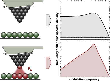
- : amplitude noise; cantilever stiffness; closed loop; detection system noise; frequency shift noise; non-contact atomic force microscopy (NC-AFM); Q-factor; spectral analysis; thermal noise; tip–sample interaction; Introduction Non-contact atomic force microscopy (NC-AFM) [1][2] is an unmatched surface
- the sample surface [2], typically a cantilever, a tuning fork, or a needle sensor [8]. The resolution of force measurements is limited by the noise in the frequency shift signal [9][10], which strongly depends on the noise floor of the detection system, the frequency response of the frequency
- demodulator (mostly a phase-locked loop detector, PLL), cantilever properties and ultimately thermal noise [11]. The footing of our work are these precursor studies, and the rigorous system analysis introduced by Polesel-Maris et al. [12], showing that the frequency shift noise at close tip–sample distance is


![[Graphic 32]](/bjnano/content/inline/2190-4286-7-181-i73.png?max-width=637&scale=1.18182) wit...
wit...

![[Graphic 34]](/bjnano/content/inline/2190-4286-7-181-i75.png?max-width=637&scale=1.18182) wit...
wit...


Effect of tetramethylammonium hydroxide/isopropyl alcohol wet etching on geometry and surface roughness of silicon nanowires fabricated by AFM lithography
Beilstein J. Nanotechnol. 2016, 7, 1461–1470, doi:10.3762/bjnano.7.138

- using AFM lithography (SPI3800N/4000) at a temperature of 24–26 °C with relative humidity of 55–65%. The contact mode, Au cantilever tip (Budgetsensors, Au-coated, ContGB-G) was used at 9 V bias voltage with 0.3 µm/s writing speed. After the AFM lithography process, thin oxide nanowires were formed on


Customized MFM probes with high lateral resolution
Beilstein J. Nanotechnol. 2016, 7, 1068–1074, doi:10.3762/bjnano.7.100

- ); AFM probes; high-resolution microscopy; magnetic force microscopy (MFM); magnetic materials; Introduction Conventional MFM probes consist of pyramidal Si or SiN tips with a ferromagnetic thin film coating (generally a CoCr alloy) mounted on a cantilever with resonance frequency and spring constant of
- also select the cantilever properties for each experiment, such as the spring constant, resonance frequency or the position of the tip on the lever. We have found neither in the literature nor in the market any MFM probe with cantilever characteristics far from the range of the aforementioned. Making
- incidence angle, it is possible to cover mainly one side of the tip pyramid. A residual magnetic film with sub-nanometre thickness was found on the remaining parts of the tip–cantilever system. No capping layer is subsequently deposited onto the Co film since, although the outermost atomic layers of cobalt


Signal enhancement in cantilever magnetometry based on a co-resonantly coupled sensor
Beilstein J. Nanotechnol. 2016, 7, 1033–1043, doi:10.3762/bjnano.7.96

- für Festkörperelektronik, Technische Universität Dresden, 01062 Dresden, Germany 10.3762/bjnano.7.96 Abstract Cantilever magnetometry is a measurement technique used to study magnetic nanoparticles. With decreasing sample size, the signal strength is significantly reduced, requiring advances of the
- technique. Ultrathin and slender cantilevers can address this challenge but lead to increased complexity of detection. We present an approach based on the co-resonant coupling of a micro- and a nanometer-sized cantilever. Via matching of the resonance frequencies of the two subsystems we induce a strong
- as nanocantilever and magnetic sample. Measurements revealed an enhancement of the commonly used frequency shift signal by five orders of magnitude compared to conventional cantilever magnetometry experiments with similar nanomagnets. With this experiment we do not only demonstrate the functionality


![[Graphic 11]](/bjnano/content/inline/2190-4286-7-96-i21.png?max-width=637&scale=1.18182) on the interaction spring constant k3. Th...
on the interaction spring constant k3. Th...
Generalized Hertz model for bimodal nanomechanical mapping
Beilstein J. Nanotechnol. 2016, 7, 970–982, doi:10.3762/bjnano.7.89

- Aleksander Labuda Marta Kocun Waiman Meinhold Deron Walters Roger Proksch Asylum Research, an Oxford Instruments company, Santa Barbara, CA, 93117, USA 10.3762/bjnano.7.89 Abstract Bimodal atomic force microscopy uses a cantilever that is simultaneously driven at two of its eigenmodes (resonant
- are sensitive to the tip–sample nanomechanical interaction parameters. To demonstrate this, a generalized theoretical framework for extracting nanomechanical sample properties from bimodal experiments is presented based on Hertzian contact mechanics. Three modes of operation for measuring cantilever
- ” or “spectroscopic” techniques. In parametric nanomechanical techniques, the sample properties are deduced from changes in the parameters of a driven cantilever that is oscillating in a (quasi) steady state while interacting with the sample surface. For example, tapping-mode AFM [16][17] (also known


![[Graphic 4]](/bjnano/content/inline/2190-4286-7-89-i40.png?max-width=637&scale=1.18182) approximation applied to Equation 6 i...
approximation applied to Equation 6 i...


Noncontact atomic force microscopy III
Beilstein J. Nanotechnol. 2016, 7, 946–947, doi:10.3762/bjnano.7.86

- -AFM) in 1994 offered an elegant solution to this problem: Instead of touching the sample surface, the probe hovers a short distance above while the micro-machined cantilever that the probe is attached to is oscillated at its resonance frequency. The attractive interaction forces acting between the
- particular, latest instrumental advances are highlighted in the form of a new design for a large-area SPM used for electrostatic force measurements, improvement of dynamic cantilever response by the utilization of reflective coatings and photothermal conversion layers, and the use of length extension