

Search results
Search for "ethylenediamine" in Full Text gives 73 result(s) in Beilstein Journal of Organic Chemistry.
Photo, thermal and chemical degradation of riboflavin
- Muhammad Ali Sheraz,
- Sadia Hafeez Kazi,
- Sofia Ahmed,
- Zubair Anwar and
- Iqbal Ahmad
Beilstein J. Org. Chem. 2014, 10, 1999–2012, doi:10.3762/bjoc.10.208
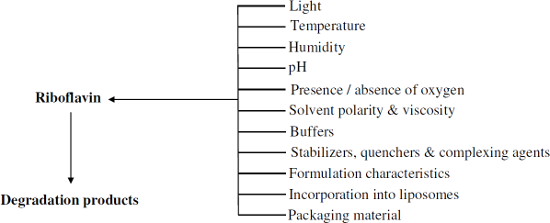
- greatest stabilizing effect by disodium ethylenediamine (EDTA) (96.2%), followed by thiourea (88.2%), methylparaben (86.4%), DL-methionine (76.3%), sodium thiosulfate (72.9%), ribonucleic acid (59.3%) and reduced glutathione (26.2%). When RF solutions were exposed to a 40 W fluorescent light (Sylvania

Graphical Abstract
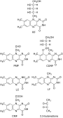
Figure 1: Structures of RF and its photoproducts.

Figure 2: A general scheme for the photodegradation of RF in aqueous solution.
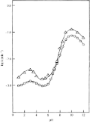
Figure 3: log k–pH profiles for the photolysis of RF in aqueous solution using UV light (∆) and visible light...

Figure 4: log k–pH profiles for the photolysis of FMF (10−4 M) in alkaline solution under aerobic (○) and ana...

Figure 5: k'–pH profiles for the photolysis of FMF (10−4 M) in acidic solution under aerobic (○) and anaerobi...

Figure 6: Plots of k` versus pH for phosphate (▲) and sulfate (●) anion-catalyzed photodegradation of RF (5 ×...

Figure 7: log kobs–pH profiles for the photolysis of RF (5 × 10⁻⁵ M) in 0.1–0.5 M borate buffer. Experimental...

Figure 8: log kobs–pH profiles for the photolysis of RF (5 × 10⁻⁵ M) in 0.2–1.0 M citrate buffer. Experimenta...

Figure 9: k'–pH profile for the photolysis of RF (5 × 10⁻⁵ M) in the presence of CF (0.5–2.5 × 10⁻⁴ M). Exper...
Photoswitchable precision glycooligomers and their lectin binding
- Daniela Ponader,
- Sinaida Igde,
- Marko Wehle,
- Katharina Märker,
- Mark Santer,
- David Bléger and
- Laura Hartmann
Beilstein J. Org. Chem. 2014, 10, 1603–1612, doi:10.3762/bjoc.10.166
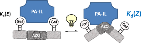
- ligands (Figure 1): Starting from an ethylenediamine functionalized trityl resin (0.0125 mmol), the first building block, i.e., TDS (8 equiv) was attached via activation with PyBOP/HOBt (8 equiv/4 equiv) and DIPEA (16 equiv) in DMF and subsequent coupling for 1 hour. After a washing step, the terminal
- ethylenediamine linker and used as resin for solid phase synthesis. 0.0125 mmol of resin were swollen in DCM for 15 min. The initial coupling to the ethylenediamine linker was performed with a 0.1 mmol building block solution (8 equiv, TDS, EDS or AZO) in DMF (0.5 mL), followed by the addition of a 0.1 mmol PyBOP

Graphical Abstract

Figure 1: Synthesis of photoswitchable precision glycooligomers via stepwise addition of building blocks on s...

Figure 2: Characterization of the E → Z photoisomerization (λ = 360 nm) of Azo-Gal(1,3,5)-5 in buffer solutio...
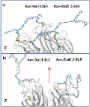
Figure 3: Structural models of Azo-Gal(1,3)-3 and Azo-Gal(1,3,5)-5 in (a) E- and (b) all-Z-configurations of ...
Biantennary oligoglycines and glyco-oligoglycines self-associating in aqueous medium
- Svetlana V. Tsygankova,
- Alexander A. Chinarev,
- Alexander B. Tuzikov,
- Nikolai Severin,
- Alexey A. Kalachev,
- Juergen P. Rabe,
- Alexandra S. Gambaryan and
- Nicolai V. Bovin
Beilstein J. Org. Chem. 2014, 10, 1372–1382, doi:10.3762/bjoc.10.140
- solvents were bought from Merck and Sigma–Aldrich. Activated esters BocGlyONSu and BocGly2ONSu were prepared as described earlier [9] from glycine or glycylglycine (Acros). Ethylenediamine and 1,10-diaminodecane were supplied from Sigma-Aldrich, and diamine NH2(CH2CH2O)3CH2CH2NH2 (1) was synthesized from

Graphical Abstract
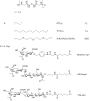
Figure 1: The structure of biantennary oligoglycines and their glyco derivatives (sp = spacer group).

Scheme 1: Synthesis of biantennary oligoglycines and their glycoderivatives.

Figure 2: Dynamics of associate formation by biantennary oligoglycines Н-Glyn-NH(СН2)10NH-Glyn-Н. a) n = 4–5,...
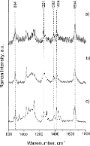
Figure 3: Raman spectra of a) [H-Gly7-NHCH2]4C; b) H-Gly4-NH(CH2)2NH-Gly4-H; c) H-Gly4-NH(CH2)10NH-Gly4-H. Th...

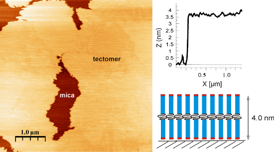
Figure 4: Model of the formation of tectomer layers by biantennary oligoglycines on a mica surface. The heigh...

Figure 5: Growth of the tectomer formed by the peptide Н-Gly4-NH(СН2)10-NHGly4-Н (concentration 0.1 mg/mL) on...

Figure 6: Growth of the tectomer formed by peptide Н-Gly4-NH(СН2)10NH-Gly4-Н (concentration 0.1 mg/mL) on a m...

Figure 7: SFM images of associates formed by peptides а) Н-Gly5-NH(СН2)2NH-Gly5-Н and b) Н-Gly5-NH(СН2)10NH-G...
Molecular recognition of surface-immobilized carbohydrates by a synthetic lectin
- Melanie Rauschenberg,
- Eva-Corrina Fritz,
- Christian Schulz,
- Tobias Kaufmann and
- Bart Jan Ravoo
Beilstein J. Org. Chem. 2014, 10, 1354–1364, doi:10.3762/bjoc.10.138
- previously [39]. Fluorescein-labeled FITC-HisHis was obtained by labeling of Cys-His-Cys with fluorescein isothiocyanate, which was achieved by using an Fmoc-protected oligo(ethylene glycol) spacer synthesized in four steps from commercially available ethylenediamine (see Supporting Information File 1). The

Graphical Abstract

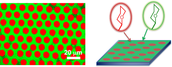
Figure 1: Molecular structures of carbohydrates (NANA, Glc, Gal, Man) immobilized on epoxide SAMs, NANA-bindi...

Figure 2: Schematic representation of the preparation of a simple carbohydrate microarray by μCP of amine-fun...

Figure 3: Optical microscopy images of water droplets selectively condensed in the areas where (A) the NANA i...

Figure 4: (A) AFM height image (zoom) of NANA ink in 10 μm stripes on an epoxide-terminated SAM; (B) Height p...

Figure 5: Fluorescence images of bifunctional carbohydrate microarrays incubated with FITC-HisHis. (A) NANA (...

Figure 6: Overlay of fluorescence images of bifunctional carbohydrate microarrays; (A) NANA (dots 10 × 5 μm) ...

Figure 7: Fluorescence images of a microarray consisting of NANA (dots 5 × 3 μm) and Man (background). (A) In...

Figure 8: Fluorescence images of a microarray of NANA (dots 5 × 3 μm) and Glc (background), first incubated w...
Flow synthesis of phenylserine using threonine aldolase immobilized on Eupergit support
- Jagdish D. Tibhe,
- Hui Fu,
- Timothy Noël,
- Qi Wang,
- Jan Meuldijk and
- Volker Hessel
Beilstein J. Org. Chem. 2013, 9, 2168–2179, doi:10.3762/bjoc.9.254
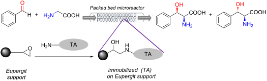
- each other which resulted in higher values for enzyme retention. For the indirect method, however, the epoxy groups were converted into aldehyde groups. These groups can only react with nucleophiles such as amino groups. During treatment of Eupergit with ethylenediamine, a coupling of two adjacent
- method the enzyme was separated from the support by a spacer element. This was formed by the reaction of ethylenediamine and glutaraldehyde. This reaction reduces the probability of blocking the active site of the enzyme which would provide higher activity retention. For the direct method, our results
- , Germany). L-threonine, β-nicotinamide adenine dinucleotide disodium salt (NADH) were purchased from AppliChem GmbH (Darmstadt, Germany). Glycine, benzaldehyde, pyridoxal-5’-phosphate (PLP), Eupergit CM, 2-mercaptoethanol, 25% glutaraldehyde solution in water, ethylenediamine and other reagents were all

Graphical Abstract

Scheme 1: Phenylserine synthesis.

Figure 1: Activity loss of TA immobilized by two different methods and as a free enzyme at 80 °C. Reproduced ...

Figure 2: Degree of immobilization versus incubation time.

Figure 3: Batch reaction using free enzyme. Reaction conditions: Reaction volume (10 mL), TA (2.7 mg, specifi...

Figure 4: Product inhibition study.

Figure 5: Effect of temperature on product yield. Reaction conditions: Reaction volume (0.250 mL), TA (1.1 mg...

Figure 6: Effect of flow rates on yield for immobilized enzymes in a packed bed microreactor (70 °C). Reactio...

Figure 7: Effect of residence time on yield for free enzymes in a Teflon tube microreactor at 70 °C. Reaction...

Figure 8: Long term enzyme stability at 70 °C. Reaction conditions: Reaction volume (0.250 mL), TA (1.1 mg, s...

Scheme 2: Synthesis of chiral α-aminoalcohol by telescoping aldolase reaction with decarboxylation.

Figure 9: Direct immobilization.

Figure 10: Indirect immobilization.

Figure 11: Flow reaction set-up using free enzyme.

Figure 12: Experimental setup for packed be microreactor.

Figure 13: Analysis of the four isomers of phenylserine on a chiral column.
A reductive coupling strategy towards ripostatin A
- Kristin D. Schleicher and
- Timothy F. Jamison
Beilstein J. Org. Chem. 2013, 9, 1533–1550, doi:10.3762/bjoc.9.175
- ethylenediamine complex of lithium acetylide in a 1:1 THF/DMSO solvent mixture at 0 °C allowed the terminal alkyne to be accessed in 84% yield without rearrangement to the internal alkyne. Silyl protection afforded alkyne 50, which was prone to decomposition upon extended storage, even at −20 °C. Hydrozirconation

Graphical Abstract

Figure 1: Structures of the ripostatins.

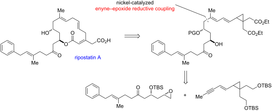
Figure 2: Retrosynthesis of ripostatin A.

Scheme 1: Nickel-catalyzed reductive coupling of alkynes and epoxides.

Figure 3: Proposed retrosynthesis of ripostatin A featuring enyne–epoxide reductive coupling and rearrangemen...

Scheme 2: Potential transition states and stereochemical outcomes for a concerted 1,5-hydrogen rearrangement.

Scheme 3: Rearrangements of vinylcyclopropanes to acylic 1,4-dienes.

Scheme 4: Synthesis of cyclopropyl enyne.

Scheme 5: Synthesis of model epoxide for investigation of the nickel-catalyzed coupling reaction.

Scheme 6: Nickel-catalyzed enyne–epoxide reductive coupling reaction.

Scheme 7: Proposed mechanism for the nickel-catalyzed coupling reaction of alkynes or enynes with epoxides.

Scheme 8: Regioselectivity changes in reductive couplings of alkynes and 3-oxygenated epoxides.

Scheme 9: Enyne reductive coupling with 1,2-epoxyoctane.

Figure 4: Initial retrosynthesis of the epoxide fragment by using dithiane coupling.

Scheme 10: Synthesis of dithiane by Claisen rearrangement.

Scheme 11: Deuterium labeling reveals that the allylic/benzylic site is most acidic.

Scheme 12: Oxy-Michael addition to δ-hydroxy-α,β-enones.

Figure 5: Revised retrosynthesis of epoxide 5.

Scheme 13: Synthesis of functionalized ketone by oxy-Michael addition.

Figure 6: Retrosynthesis by using iodocylization to introduce the epoxide.

Scheme 14: Synthesis of ketone 57 using thiazolidinethione chiral auxiliary.

Figure 7: Retrosynthesis involving decarboxylation of a β-ketoester.

Scheme 15: Synthesis of β-ketoester 61.

Scheme 16: Decarboxylation of 61 under Krapcho conditions.

Scheme 17: Improved synthesis of 63 and attempted iodocyclization.

Figure 8: Retrosynthesis utilizing Rychnovsky’s cyanohydrin acetonide methodology.

Scheme 18: Synthesis of cyanohydrin acetonide and attempted alkylation with epoxide.

Scheme 19: Allylation of acetonide and conversion to aldehyde.

Scheme 20: Synthesis of the epoxide precursor by an aldol−decarboxylation sequence.
Simple and rapid hydrogenation of p-nitrophenol with aqueous formic acid in catalytic flow reactors
- Rahat Javaid,
- Shin-ichiro Kawasaki,
- Akira Suzuki and
- Toshishige M. Suzuki
Beilstein J. Org. Chem. 2013, 9, 1156–1163, doi:10.3762/bjoc.9.129
- demonstrates the robustness of the present catalytic reactors. Experimental Materials and reagents Reagent-grade formic acid (HCO2H, 98%), p-nitrophenol, palladium acetate [Pd(CH3COO)2], silver nitrate (AgNO3), disodium ethylenediamine tetraacetate (EDTA–Na2), ammonia (NH3, 28%), hydrazine monohydrate, nitric

Graphical Abstract

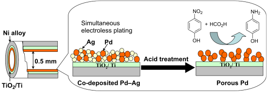
Figure 1: (a) Graphical presentation of Pd–Ag co-plating and sequential removal of Ag to give a porous Pd sur...

Figure 2: Schematic diagram of experimental setup used for the catalytic hydrogenation of p-nitrophenol.

Scheme 1: Hydrogenation of p-nitrophenol with formic acid.

Figure 3: Influence of temperature on the conversion of 0.01 M p-nitrophenol with 0.1 M formic acid at 30 °C ...

Figure 4: Effect of residence time on the conversion of 0.01 M p-nitrophenol with 0.1 M formic acid at 30 °C ...

Figure 5: Effect of the concentration of formic acid on the conversion of 0.01 M p-nitrophenol. The formic ac...

Figure 6: Effect of pH on the conversion of 0.01 M p-nitrophenol by using 0.05 M formic acid. The porous PdO ...

Figure 7: Long-term testing for continuous hydrogenation of 0.01 M p-nitrophenol with 0.05 M formic acid in t...
A one-pot catalyst-free synthesis of functionalized pyrrolo[1,2-a]quinoxaline derivatives from benzene-1,2-diamine, acetylenedicarboxylates and ethyl bromopyruvate
- Mohammad Piltan,
- Loghman Moradi,
- Golaleh Abasi and
- Seyed Amir Zarei
Beilstein J. Org. Chem. 2013, 9, 510–515, doi:10.3762/bjoc.9.55
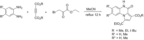
- -diaminobenzene, dialkyl acetylenedicarboxylates, and ethyl bromopyruvate forms pyrrolo[1,2-a]quinoxaline derivatives in good yields. Ethylenediamine also reacts under similar conditions to produce new pyrrolo[1,2-a]pyrazine derivatives. Keywords: acetylenedicarboxylates; benzene-1,2-diamine; ethyl bromopyruvate
- react with ethyl bromopyruvate (3) to generate the intermediate 6. This intermediate undergoes a series of cyclization and elimination reactions to generate the product 4a. We then investigated the reaction between ethylenediamine (8) and activated acetylenic compounds in the presence of ethyl

Graphical Abstract

Scheme 1: Proposed mechanism for the formation of compound 4a.

Scheme 2: Synthesis of pyrrolo[1,2-a]pyrazine derivatives 9a,b.
Spin state switching in iron coordination compounds
- Philipp Gütlich,
- Ana B. Gaspar and
- Yann Garcia
Beilstein J. Org. Chem. 2013, 9, 342–391, doi:10.3762/bjoc.9.39
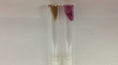
- -tetrazole)6]X2 complexes, which are nearly regular octahedral [50]. Another possibility to fulfill the condition for thermal spin crossover to occur is the coordination of a hexadentate system, such as the mixed aliphatic/heterocyclic tetrakis(2-pyridylmethyl)ethylenediamine) [51] or the completely

Graphical Abstract

Figure 1: Change of electron distribution between HS and LS states of an octahedral iron(II) coordination com...

Figure 2: Types of spin transition curves in terms of the molar fraction of HS molecules, γHS(T), as a functi...
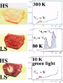
Figure 3: Single crystal UV–vis spectra of the spin crossover compound [Fe(ptz)6](BF4)2 (ptz = 1-propyltetraz...
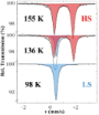
Figure 4: Thermal spin crossover in [Fe(ptz)6](BF4)2 (ptz = 1-propyltetrazole) recorded at three different te...

Figure 5: (a) Mössbauer spectra of the LS compound [Fe(phen)3]X2 recorded over the temperature range 300–5 K....

Figure 6: (left) Demonstration of light-induced spin state trapping (LIESST) in [Fe(ptz)6]BF4)2 with 57Fe Mös...

Figure 7: Schematic representation of the pressure influence (p2 > p1) on the LS and HS potential wells of an...

Figure 8: χMT versus T curves at different pressures for [Fe(phen)2(NCS)2], polymorph II. (Reproduced with pe...

Figure 9: Molecular structure (a) and γHS(T) curves at different pressures for [CrI2(depe)2] (b) (Reproduced ...

Figure 10: HS molar fraction γHS versusT at different pressures for [Fe(phy)2](BF4)2. The hysteresis loop broa...

Figure 11: Proposed structure of the polymeric [Fe(4R-1,2,4-triazole)3]2+ spin crossover cation (a) and plot o...

Figure 12: Temperature dependence of the HS fraction γHS(T), determined from Mössbauer spectra of [Fe(II)xZn1-x...
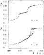
Figure 13: Influence of the noncoordinated anion on the spin transition curve γHS(T) near the transition tempe...

Figure 14: Spin transition curves γHS(T) for different solvates of the SCO complexes. [Fe(II)(2-pic)3]Cl2·Solv...
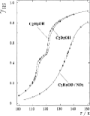
Figure 15: ST curves γHS(T) of the deuterated solvates of [Fe(II)(2-pic)3]Cl2·Solv with Solv = C2D5OH and C2H5...

Figure 16: Sketch of the two-step spin transition; [LS–LS] pair is diamagnetic, [LS–HS] is paramagnetic and th...

Figure 17: (left) Temperature dependence of χMT for {[Fe(L)(NCX)2]2bpym}(L = bpym or bt and X = S or Se). (rig...

Figure 18: Temperature dependence of χMT for [bpym, NCS−] (left) and [bpym, NCSe−] (right) at different pressu...

Figure 19: 57Fe Mössbauer spectra of [bpym, NCSe−] measured at 4.2 K at zero field (a) and at 5 T (b) (see tex...

Figure 20: Temperature dependence of χMT for [Fe2(L)3](ClO4)4·2H2O showing a complete two-step spin conversion...

Figure 21: (a) View of the dinuclear unit in the crystal structure of [Fe2(Hsaltrz)5(NCS)4]·4MeOH. (b) Tempera...

Figure 22: (left) AFM pattern recorded in tapping mode at room temperature on hexagonal single crystals of [Fe3...

Figure 23: (right) Stepwise SCO in an Fe4 [2 × 2] grid, which reveals a smooth magnetic profile under ambient ...

Figure 24: (left) View of the discrete nanoball made of Fe(II) SCO units as well as Cu(I) building blocks. (ri...

Figure 25:
(left) Linear dependency between T1/2 in the heating (Δ) and cooling (![[Graphic 1]](/bjoc/content/inline/1860-5397-9-39-i3.png?max-width=637&scale=1.18182) ) modes versus the anion volu...
) modes versus the anion volu...

Figure 26: (left) View of the linear chain structure of [Fe(1,2-bis(tetrazol-1-yl)propane)3]2+ along the a axi...

Figure 27: (left) View of the 2D layered structure of [Fe(btr)2(NCS)2]·H2O (at 293 K). The water molecules (in...

Figure 28: (left) Three interpenetrated square networks for [Fe(bpb)2(NCS)2]·MeOH. (right) χMT versus T plot s...

Figure 29: Part of the crystal structure of [Fe{N(entz)3}](BF4)2 (T = 293 K) [335,336]. (Reproduced with permission fro...

Figure 30: (left) Projection of the crystal structure of [Fe(btr)3](ClO4)2 along the c axis revealing a 3D str...

Figure 31: Size-dependent SCO properties in [Fe(pz)Pt(CN)4] (left), change of color upon spin state transition...

Figure 32: Schematic showing the epitaxial growth of polymer {Fe(pz)[Pt(CN)4]} and the spin transition propert...

Figure 33: Microcontact printing (μCP) of nanodots on Si-wafer of [Fe(ptz)6](BF4)2 after deposition of crystal...

Figure 34: (left) Projection of the two independent cations of [Fe(C6–trenH)]2+ with atom numbering scheme (15...
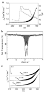
Figure 35: (a) χMT versus T for [Fe(C16-trenH)]Cl2·0.5H2O and variation of the distance d with temperature (T)...

Figure 36: Schematic illustration of the structure of compounds [Fe(Cn-tba)3]X2 adopting a columnar mesophase ...

Figure 37: Temperature dependence of the magnetic moment (M) at 1000 Oe and DSC profiles (inset; 5 °C/min) of ...

Figure 38: Porous structure of the SCO-PMOFs {Fe(pz)[M(II)(CN)4]} (left), representation of the host–guest int...

Figure 39: Porous structure of the guest-free SCO-PMOF’s {Fe(pz)[M(II)(CN)4]} (left), magnetic properties of t...

Figure 40: (left) The 3D porous structure of {Fe(pz)[Pt(CN)4]}·0.5(CS(NH2)2) (1) and {Fe(pz)[Pd(CN)4]}·1.5H2O·...
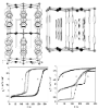
Figure 41: Top: The 3D porous structure of {Fe(dpe)[Pt(CN)4]}·phenazine in a direction close to [101] emphasiz...

Figure 42: View of the segregated stacking of [Ni(dmit)2]− and [Fe(sal2-trien)]+ in [Fe(qsal)2][Ni(dmit)2]3·CH3...

Figure 43: Thin films based on Fe(III) compounds coordinated to Terthienyl-substituted QsalH ligands [434] together...

Figure 44: Left: Temperature-dependent emission spectra for [Fe2(Hsaltrz)5(NCS)4]·4MeOH at λex = 350 nm over t...
Amino-substituted diazocines as pincer-type photochromic switches
- Hanno Sell,
- Christian Näther and
- Rainer Herges
Beilstein J. Org. Chem. 2013, 9, 1–7, doi:10.3762/bjoc.9.1
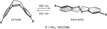
- should be suitable as molecular pincers. To demonstrate this property we studied the binding of ethylenediamine to the two isomers of the acetamido derivative 5 (Figure 5). We carried out 1H NMR titrations of cis-5 as well as of the photostationary mixture of cis-5 and trans-5 upon irradiation with light
- of a wavelength of 405 nm with ethylenediamine in acetonitrile. The spectra showed a significant chemically induced shift (CIS) of the acetamide protons of both isomers upon addition of ethylenediamine. Equilibrium analysis with respect to the CIS binding isotherms by means of nonlinear least-squares
- methods (for details see Supporting Information File 1) [18][19] yielded a binding constant for the 1:1 ethylenediamine complex of the cis isomer of Ka,cis = 0.88 ± 0.03 M−1. For the corresponding complex of the trans isomer a slightly lower binding constant of Ka,trans = 0.61 ± 0.05 M−1 was determined in

Graphical Abstract

Figure 1: Configurations and conformations of 5,6-dihydrodibenzo[c,g][1,2]diazocine (1), and DFT (B3LYP/6-31G...

Scheme 1: Synthesis of 3,3’-diamino-EBAB 4 and its acetamide derivative 5.

Figure 2: Crystal structures of the cis isomers of 3,3’-diamino-EBAB 4 and its acetamide derivative 5. The at...
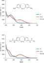
Figure 3: UV–vis spectra of the diazocine derivatives 3,3’-diamino-EBAB 4 and its bisamide derivative 5 in ac...

Figure 4: Absorbances of solutions of 4 and 5 in acetonitrile at 405 nm (red) and 485 nm (blue) in the corres...

Figure 5: DFT-calculated structure (B3LYP/6-31+G**) of a complex of 5 with ethylenediamine as a conceivable m...
New efficient ligand for sub-mol % copper-catalyzed C–N cross-coupling reactions running under air
- Per-Fredrik Larsson,
- Peter Astvik and
- Per-Ola Norrby
Beilstein J. Org. Chem. 2012, 8, 1909–1915, doi:10.3762/bjoc.8.221
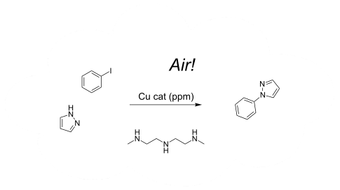
- mono-methylating ethylene amines were ineffective for the ethylenediamine motif; hence, there is an opportunity for further ligand synthesis development. Experimental General: All the experiments were carried out under inert atmosphere (nitrogen). DMEDA, iodobenzene and dodecane were distilled over

Graphical Abstract

Scheme 1: Synthetic procedure for N,N''-dimethyldiethylene triamine.

Scheme 2: Standard reaction for the kinetic study.

Figure 1: Kinetic profile for varying [DMDETA].

Figure 2: Reaction order for copper from 0.025–0.64 mol %.

Figure 3: DMEDA versus DMDETA under air and nitrogen atmosphere.

Scheme 3: Long-chained aliphatic amines as ligands.
Enaminones in a multicomponent synthesis of 4-aryldihydropyridines for potential applications in photoinduced intramolecular electron-transfer systems
- Nouria A. Al-Awadi,
- Maher R. Ibrahim,
- Mohamed H. Elnagdi,
- Elizabeth John and
- Yehia A. Ibrahim
Beilstein J. Org. Chem. 2012, 8, 441–447, doi:10.3762/bjoc.8.50

- % yield by microwave irradiation with R-1-phenylethylamine in this three-component reaction. The bis(dihydropyridines) 5a,b were obtained in 75–92% yield with ethylenediamine and 1,3-diaminopropane as the primary amines, respectively. The 4-(1-naphthyl)dihydropyridines 6a–f and 4-(phenanthren-9-yl

Graphical Abstract

Scheme 1: 2,6-Dihydropyridine-3,5-dicarboxylates as useful organic dyads.

Scheme 2: Synthesis of dihydropyridine derivatives from enaminones.

Scheme 3: Dihydropyridine derivatives 4–7 and enaminone 8.

Figure 1: ORTEP of compounds 4b, 6d, 6f and 7a.

Figure 2: Absorption spectra of compounds 2j, 6a–f and 7a,b in acetonitrile (1 × 10⁻⁴ M).
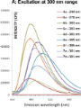
Figure 3: Emission spectra of compounds 4a, 6a–f and 7a,b after excitation at their absorption λmax in the ra...
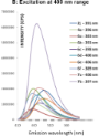
Figure 4: Emission spectra of compounds 2j, 4a, 6a–f and 7a,b after excitation at their absorption λmax in th...

Scheme 4: Synthesis of dihydropyridines from an enamino aldehyde, an enamino ester and an enaminonitrile.

Scheme 5: Nitric acid oxidation of dihydropyridines 2a–c and 6a.

Figure 5: ORTEP of compound 15d.
Fifty years of oxacalix[3]arenes: A review
- Kevin Cottet,
- Paula M. Marcos and
- Peter J. Cragg
Beilstein J. Org. Chem. 2012, 8, 201–226, doi:10.3762/bjoc.8.22

Graphical Abstract

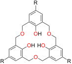
Figure 1: Calixarenes and expanded calixarenes: p-tert-Butylcalix[4]arene (1), p-tert-butyldihomooxacalix[4]a...

Figure 2: Conventional nomenclature for oxacalix[n]arenes.

Scheme 1: Synthesis of oxacalix[3]arenes: (i) Formaldehyde (37% aq), NaOH (aq), 1,4-dioxane; glacial acetic a...

Figure 3: p-tert-Butyloctahomotetraoxacalix[4]arene (4a) [16].

Figure 4: X-ray crystal structure of 3a showing phenolic hydrogen bonding (IUCr ID AS0508) [17].

Scheme 2: Stepwise synthesis of asymmetric oxacalix[3]arenes: (i) MOMCl, Adogen®464; (ii) 2,2-dimethoxypropan...
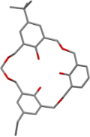
Figure 5: X-ray crystal structure of heptahomotetraoxacalix[3]arene 5 (CCDC ID 166088) [21].

Scheme 3: Oxacalix[3]arene synthesis by reductive coupling: (i) Me3SiOTf, Et3SiH, CH2Cl2; R1, R2 = I, Br, ben...

Scheme 4: Oxacalix[3]naphthalene: (i) HClO4 (aq), wet CHCl3 (R = tert-butyl, 6a, H, 6b) [20].

Figure 6: Conformers of 3a.

Scheme 5: Origin of the 25:75 cone:partial-cone statistical distribution of O-substituted oxacalix[3]arenes (p...

Scheme 6: Synthesis of alkyl ethers 7–10: (i) Alkyl halide, NaH, DMF [24].

Scheme 7: Synthesis of a pyridyl derivative 11a: (i) Picolyl chloride hydrochloride, NaH, DMF [26,27].

Figure 7: X-ray crystal structure of partial-cone 11a (CCDC ID 150580) [26].

Scheme 8: Lower-rim ethyl ester synthesis: (i) Ethyl bromoacetate, NaH, t-BuOK or alkali metal carbonate, THF...

Scheme 9: Forming chiral receptor 13: (i) Ethyl bromoacetate, NaH, THF; (ii) NaOH, H2O/1,4-dioxane; (iii) S-P...
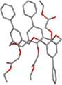
Figure 8: X-ray crystal structure of 16 (IUCr ID PA1110) [32].

Scheme 10: Lower rim N,N-diethylamide 17a: (i) N,N-Diethylchloroacetamide, NaH, t-BuOK or alkali metal carbona...

Scheme 11: Capping the lower rim: (i) N,N-Diethylchloroacetamide, NaH, THF; (ii) NaOH, H2O/1,4-dioxane; (iii) ...

Figure 9: X-ray crystal structure of 18 (CCDC ID 142599) [33].

Scheme 12: Extending the lower rim: (i) Glycine methyl ester, HOBt, dicyclohexycarbodiimide (DCC), CH2Cl2; (ii...

Scheme 13: Synthesis of N-hydroxypyrazinone derivative 23: (i) 1-[3-(Dimethylamino)propyl]-3-ethylcarbodiimide...

Scheme 14: Synthesis of 24: (i) 1-Adamantyl bromomethyl ketone, NaH, THF [39].

Scheme 15: Synthesis of 25 and 26: (i) (Diphenylphosphino)methyl tosylate, NaH, toluene; (ii) phenylsilane, to...

Figure 10: X-ray crystal structure of 27 in the partial-cone conformer (CCDC ID SUP 90399) [41].

Scheme 16: Synthesis of strapped oxacalix[3]arene derivatives 28 and 29: (i) N,N’-Bis(chloroacetyl)-1,2-ethyle...

Figure 11: A chiral oxacalix[3]arene [45].

Figure 12: X-ray crystal structure of asymmetric oxacalix[3]arene 30 incorporating t-Bu, iPr and Et groups (CC...

Scheme 17: Reactions of an oxacalix[3]arene incorporating an upper-rim Br atom with (i) Pd(OAc)2, PPh3, HCO2H,...

Scheme 18: Synthesis of acid 39: (i) NaOH, EtOH/H2O, HCl (aq) [47].

Figure 13: Two forms of dimeric oxacalix[3]arene 40 [47].

Scheme 19: Capping the upper rim: (i) t-BuLi, THF, −78 °C; (ii) NaBH4, THF/EtOH; (iii) 1,3,5-tris(bromomethyl)...

Figure 14: Oxacalix[3]arene capsules 46 and 47 formed through coordination chemistry [52,53].

Figure 15: X-ray crystal structure of the 3b-vanadyl complex (CCDC ID 240185) [57].

Scheme 20: Effect of Ti(IV)/SiO2 on 3a: (i) Ti(OiPr)4, toluene; (ii) triphenylsilanol, toluene; (iii) partiall...

Figure 16: X-ray crystal structures of oxacalix[3]arene complexes with rhenium: 3b∙Re(CO)3 (CCDC ID 620981, le...

Figure 17: X-ray crystal structure of the La2·3a2 complex (CSD ID TIXXUT) [60].

Figure 18: X-ray crystal structures of [3a∙UO2]− with a cavity-bound cation (CCDC ID 135575, left) and without...
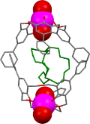
Figure 19: X-ray crystal structure of a supramolecule comprising two [3g·UO2]− complexes that encapsulate a di...

Figure 20: X-ray crystal structure of oxacalix[3]arene 49 capable of chiral selectivity (CSD ID HIGMUF) [65].
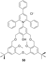
Figure 21: The structure of derivative 50 incorporating a Reichardt dye [66].

Figure 22: Phosphorylated oxacalix[3]arene complexes with transition metals: (Left to right) 26∙Au, 26∙Mo(CO)3...
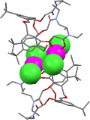
Figure 23: X-ray crystal structure of [17a·HgCl2]2 (CCDC ID 168653) [69].

Figure 24: X-ray crystal structures of 3f with C60 (CCDC ID 182801, left) [76] and a 1,4-bis(9-fluorenyl) C60 deri...

Figure 25: X-Ray crystal structure of 3i and 6a encapsulating C60 (CCDC ID 102473 and 166077) [23,79].
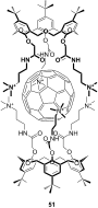
Figure 26: A C60 complexing cationic oxacalix[3]arene 51 [81].

Figure 27: An oxacalix[3]arene-C60 self-associating system 53 [87].

Scheme 21: Synthesis of fluorescent pyrene derivative 55: (i) Propargyl bromide, acetone; (ii) CuI, 1-azidomet...

Scheme 22: Synthesis of responsive rhodamine derivative 57: (i) DCC, CH2Cl2 [91].

Scheme 23: Synthesis of nitrobenzyl derivative 58: (i) 1-Bromo-4-nitrobenzyl acetate, K2CO3, refluxing acetone...

Figure 28: X-ray crystal structure of [Na2∙17a](PF6)2 (CCDC ID 116656) [97].
An overview of the key routes to the best selling 5-membered ring heterocyclic pharmaceuticals
- Marcus Baumann,
- Ian R. Baxendale,
- Steven V. Ley and
- Nikzad Nikbin
Beilstein J. Org. Chem. 2011, 7, 442–495, doi:10.3762/bjoc.7.57
- (Scheme 37). Also, a condensation reaction between ethylenediamine and acetic acid catalysed by γ-Al2O3 at high temperatures gives 2-methylimidazole (187) in approximately 90% yield [56]. Elz and Heil [57] prepared the 1,2,3,9-tetrahydro-4H-carbazol-4-one (140) by the reaction of phenylhydrazine (138

Graphical Abstract
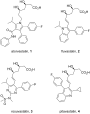
Figure 1: Structures of atorvastatin and other commercial statins.

Figure 2: Structure of compactin.

Scheme 1: Synthesis of pentasubstituted pyrroles.

Scheme 2: [3 + 2] Cycloaddition to prepare 5-isopropylpyrroles.

Scheme 3: Regiospecific [3 + 2] cycloaddition to prepare the pyrrole scaffold.

Scheme 4: Formation of the pyrrole core of atorvastatin via [3 + 2] cycloaddition.

Scheme 5: Formation of pyrrole 33 via the Paal–Knorr reaction.

Scheme 6: Convergent synthesis towards atorvastatin.

Figure 3: Binding pocket of sunitinib in the TRK KIT.

Scheme 7: Synthesis of sunitinib.

Scheme 8: Alternative synthesis of sunitinib.

Scheme 9: Key steps in the syntheses of sumatriptan and zolmitriptan.

Scheme 10: Introduction of the N,N-dimethylaminoethyl side chain.

Scheme 11: Japp–Klingemann reaction in the synthesis of sumatriptan.

Scheme 12: Synthesis of the intermediate sulfonyl chlorides 62 and 63.

Scheme 13: Alternative introduction of the sulfonamide.

Scheme 14: Negishi-type coupling to benzylic sulfonamides.

Scheme 15: Heck reaction used to introduce the sulfonamide side chain of naratriptan.

Scheme 16: Synthesis of the oxazolinone appendage of zolmitriptan.

Scheme 17: Grandberg indole synthesis used in the preparation of rizatriptan.

Scheme 18: Improved synthesis of rizatriptan.

Scheme 19: Larock-type synthesis of rizatriptan.

Scheme 20: Synthesis of eletriptan.

Scheme 21: Heck coupling for the indole system in eletriptan.

Scheme 22: Attempted Fischer indole synthesis of elatriptan.

Scheme 23: Successful Fischer indole synthesis for eletriptan.

Scheme 24: Mechanistic rationale for the Bischler–Möhlau reaction.

Scheme 25: Bischler-type indole synthesis used in the fluvastatin sodium synthesis.

Scheme 26: Palladium-mediated synthesis of ondansetron.

Scheme 27: Fischer indole synthesis of ondansetron.

Scheme 28: Optimised Pictet–Spengler reaction towards tadalafil.

Figure 4: Structures of carvedilol 136 and propranolol 137.

Scheme 29: Synthesis of the carbazole core of carvedilol.

Scheme 30: Alternative syntheses of 4-hydroxy-9H-carbazole.

Scheme 31: Convergent synthesis of etodolac.

Scheme 32: Alternative synthesis of etodolac.

Figure 5: Structures of imidazole-containing drugs.

Scheme 33: Synthesis of functionalised imidazoles towards losartan.

Scheme 34: Direct synthesis of the chlorinated imidazole in losartan.

Scheme 35: Synthesis of trisubstituted imidazoles.

Scheme 36: Preparation of the imidazole ring in olmesartan.

Scheme 37: Synthesis of ondansetron.

Scheme 38: Alternative route to ondansetron and its analogues.

Scheme 39: Proton pump inhibitors and synthesis of esomeprazole.

Scheme 40: Synthesis of benzimidazole core pantoprazole.

Figure 6: Structure of rabeprazole 194.

Scheme 41: Synthesis of candesartan.

Scheme 42: Alternative access to the candesartan key intermediate 216.

Scheme 43: .Medicinal chemistry route to telmisartan.

Scheme 44: Improved synthesis of telmisartan.

Scheme 45: Synthesis of zolpidem.

Scheme 46: Copper-catalysed 3-component coupling towards zolpidem.

Figure 7: Structure of celecoxib.

Scheme 47: Preparation of celecoxib.

Scheme 48: Alternative synthesis of celecoxib.

Scheme 49: Regioselective access to celecoxib.

Scheme 50: Synthesis of pazopanib.

Scheme 51: Syntheses of anastrozole, rizatriptan and letrozole.

Scheme 52: Regioselective synthesis of anastrozole.

Scheme 53: Triazine-mediated triazole formation towards anastrozole.

Scheme 54: Alternative routes to 1,2,4-triazoles.

Scheme 55: Initial synthetic route to sitagliptin.

Figure 8: Binding of sitagliptin within DPP-IV.

Scheme 56: The process route to sitagliptin key intermediate 280.

Scheme 57: Synthesis of maraviroc.

Scheme 58: Synthesis of alprazolam.

Scheme 59: The use of N-nitrosoamidine derivatives in the preparation of fused benzodiazepines.

Figure 9: Structures of itraconazole, ravuconazole and voriconazole.

Scheme 60: Synthesis of itraconazole.

Scheme 61: Synthesis of rufinamide.

Scheme 62: Representative tetrazole formation in valsartan.

Figure 10: Structure of tetrazole containing olmesartan, candesartan and irbesartan.

Scheme 63: Early stage introduction of the tetrazole in losartan.

Scheme 64: Synthesis of cilostazol.

Figure 11: Structure of cefdinir.

Scheme 65: Semi-synthesis of cefdinir.

Scheme 66: Thiazole syntheses towards ritonavir.

Scheme 67: Synthesis towards pramipexole.

Scheme 68: Alternative route to pramipexole.

Scheme 69: Synthesis of famotidine.

Scheme 70: Efficient synthesis of the hyperuricemic febuxostat.

Scheme 71: Synthesis of ziprasidone.

Figure 12: Structure of mometasone.

Scheme 72: Industrial access to 2-furoic acid present in mometasone.

Scheme 73: Synthesis of ranitidine from furfuryl alcohol.

Scheme 74: Synthesis of nitrofurantoin.

Scheme 75: Synthesis of benzofuran.

Scheme 76: Synthesis of amiodarone.

Scheme 77: Synthesis of raloxifene.

Scheme 78: Alternative access to the benzo[b]thiophene core of raloxifene.

Scheme 79: Gewald reaction in the synthesis of olanzapine.

Scheme 80: Alternative synthesis of olanzapine.
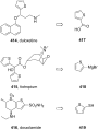
Figure 13: Access to simple thiophene-containing drugs.

Scheme 81: Synthesis of clopidogrel.

Scheme 82: Pictet–Spengler reaction in the preparation of tetrahydrothieno[3,2-c]pyridine (422).

Scheme 83: Alternative synthesis of key intermediate 422.

Figure 14: Co-crystal structures of timolol (left) and carazolol (right) in the β-adrenergic receptor.

Scheme 84: Synthesis of timolol.

Scheme 85: Synthesis of tizanidine 440.

Scheme 86: Synthesis of leflunomide.

Scheme 87: Synthesis of sulfamethoxazole.

Scheme 88: Synthesis of risperidone.

Figure 15: Relative abundance of selected transformations.

Figure 16: The abundance of heterocycles within top 200 drugs (5-membered rings).
Identification and synthesis of impurities formed during sertindole preparation
- I. V. Sunil Kumar,
- G. S. R. Anjaneyulu and
- V. Hima Bindu
Beilstein J. Org. Chem. 2011, 7, 29–33, doi:10.3762/bjoc.7.5
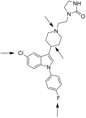
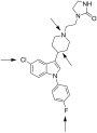
- sertindole. Sertindole (1), process related impurities and metabolites. Reagents and conditions: i) K2CO3, CuBr, ethylenediamine, DMF 130–135 °C; ii) CH3COOH, CF3COOH, 100–110 °C; iii) PtO2/H2, methanol, 30–35 °C; iv) K2CO3, KI, methylisobutyl ketone (MIBK),110–115 °C. Reagents, conditions (and yields): i
- , conditions (and yields): i) 12, K2CO3, Cu(II)Br, ethylenediamine, DMF, 130–135 °C, (51%); ii) 14, CH3COOH, CF3COOH, 100–105 °C (57%); iii) (a) pH adjusted to 6–7; (b) PtO2/H2, MeOH, 30–35 °C; (c) column chromatography (33.3%); iv) 16, K2CO3, KI, MIBK, reflux (64.3%). Reagents, conditions (and yield): i) (a
Graphical Abstract

Figure 1: Sertindole (1), process related impurities and metabolites.

Scheme 1: Reagents and conditions: i) K2CO3, CuBr, ethylenediamine, DMF 130–135 °C; ii) CH3COOH, CF3COOH, 100...

Scheme 2: Reagents, conditions (and yields): i) (a) pH adjusted to 6; (b) Pd/C, HCOONH4, AcOH, MeOH, reflux (...

Scheme 3: Reagents, conditions (and yields): i) 16, K2CO3, KI, MIBK, reflux (73.9%).

Scheme 4: Reagents, conditions (and yields): i) Cs2CO3, DMF, 130–135 °C; ii) 14, CH3COOH, CF3COOH, 100–105 °C...

Scheme 5: Reagents, conditions (and yields): i) (a) pH adjusted to 6–7; (b) H2, PtO2, MeOH, AcOH, 30–35 °C (7...

Scheme 6: Reagents, conditions (and yields): i) 12, K2CO3, Cu(II)Br, ethylenediamine, DMF, 130–135 °C, (51%);...

Scheme 7: Reagents, conditions (and yield): i) (a) 16, Et3N, NaI, CH3CN, reflux; (b) column chromatography (1...

Scheme 8: Reagents, conditions (and yield): i) (a) mCPBA, MeOH, 40–45 °C; (b) column chromatography (52.2%).
Redox-active tetrathiafulvalene and dithiolene compounds derived from allylic 1,4-diol rearrangement products of disubstituted 1,3-dithiole derivatives
- Filipe Vilela,
- Peter J. Skabara,
- Christopher R. Mason,
- Thomas D. J. Westgate,
- Asun Luquin,
- Simon J. Coles and
- Michael B. Hursthouse
Beilstein J. Org. Chem. 2010, 6, 1002–1014, doi:10.3762/bjoc.6.113

- hindrance by the aromatic units towards the formyl group, compound 21 [4] was reacted with ethylenediamine in the presence of a catalytic amount of acetic acid (Scheme 5). The Schiff base product 22 was obtained in 62% yield as a pale brown crystalline solid. Although highly strained and buckled TTF
- , 109.4, 104.4, 98.9, 56.0, 55.7, 37.1 and 19.5; νmax (KBr)/cm−1 1650, 1610, 1503, 1294, 1208 and 1033. N,N’-Bis{5-[bis(2,4-dimethoxyphenyl)methyl]-2-thioxo-[1,3]dithiole-4-ylmethylene}ethan-1,2-diamine (22) Compound 21 (0.50 g, 1.12 mmol) was dissolved in methanol (50 cm3). Ethylenediamine (0.06 g, 1.12
- ), 2,4-dimethoxybenzaldehyde (1 equiv), then repeat, −78 °C, THF; (ii) HClO4, CH2Cl2, rt. Reagents and conditions: (i) ethylenediamine, AcOH, MeOH; (ii) P(OEt)3, 120 °C, 3 h. Reagents and conditions: (i) P(OEt)3, reflux; (ii) Hg(OAc)2, CH2Cl2/AcOH; (iii) NaOEt, THF, reflux, then Bu4NBr and NiCl2·6H2O, rt

Graphical Abstract

Figure 1: Chemical structures of compounds 1–3.

Scheme 1: Acid-catalysed behaviour of 4,5-bis(2-arylhydroxymethyl)-1,3-dithiole-2-thiones 2.

Scheme 2: The proposed mechanism for the formation of 3.

Scheme 3: The proposed mechanism for the decomposition of 13 in the presence of perchloric acid.

Figure 2: Generalised structure of diol 17.

Scheme 4: Reagents and conditions: (i) LDA (1 equiv), 2,4-dimethoxybenzaldehyde (1 equiv), then repeat, −78 °...

Scheme 5: Reagents and conditions: (i) ethylenediamine, AcOH, MeOH; (ii) P(OEt)3, 120 °C, 3 h.

Figure 3: Molecular structure and numbering scheme of compound 22 with Hs omitted.

Scheme 6: Reagents and conditions: (i) P(OEt)3, reflux; (ii) Hg(OAc)2, CH2Cl2/AcOH; (iii) NaOEt, THF, reflux,...

Figure 4: Molecular structure of 28 with the tetrabutylammonium cation omitted.

Figure 5: Packing diagram of 28 identifying close intermolecular contacts.

Figure 6: UV–visible spectra of 3, 25, 27 and 28 in CH2Cl2 solution.

Figure 7: Cyclic voltammograms of compounds 3, 25, 27, and 28. Glassy carbon working electrode, using Pt wire...
Molecular recognition of organic ammonium ions in solution using synthetic receptors
- Andreas Späth and
- Burkhard König
Beilstein J. Org. Chem. 2010, 6, No. 32, doi:10.3762/bjoc.6.32

Graphical Abstract

Figure 1: Biologically important amines and quaternary ammonium salts: histamine (1), dopamine (2) and acetyl...

Figure 2: Crown ether 18-crown-6.

Figure 3: Conformations of 18-crown-6 (4) in solvents of different polarity.

Figure 4: Binding topologies of the ammonium ion depending on the crown ring size.
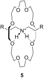
Figure 5: A “pseudorotaxane” structure consisting of 24-crown-8 and a secondary ammonium ion (5); R = Ph.

Figure 6: Typical examples of azacrown ethers, cryptands and related aza macrocycles.

Figure 7: Binding of ammonium to azacrown ethers and cryptands [111-113].

Figure 8: A 19-crown-6-ether with decalino blocking groups (11) and a thiazole-dibenzo-18-crown-6-ether (12).

Figure 9: 1,3-Bis(6-oxopyridazin-1-yl)propane derivatives 13 and 14 by Campayo et al.

Figure 10: Fluorescent azacrown-PET-sensors based on coumarin.

Figure 11: Two different pyridino-cryptands (17 and 18) compared to a pyridino-crown (19); chiral ammonium ion...

Figure 12: Pyridino-18-crown-6 ligand (21), a similar acridino-18-crown-6 ligand (22) and a structurally relat...

Figure 13: Ciral pyridine-azacrown ether receptors 24.

Figure 14: Chiral 15-crown-5 receptors 26 and an analogue 18-crown-6 ligand 27 derived from amino alcohols.

Figure 15: C2-symmetric chiral 18-crown-6 amino alcohol derivatives 28 and related macrocycles.

Figure 16: Macrocycles with diamide-diester groups (30).

Figure 17: C2-symmetric chiral aza-18-crown-6 ethers (31) with phenethylamine residues.

Figure 18: Chiral C-pivot p-methoxy-phenoxy-lariat ethers.

Figure 19: Chiral lariat crown ether 34.

Figure 20: Sucrose-based chiral crown ether receptors 36.
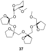
Figure 21: Permethylated fructooligosaccharide 37 showing induced-fit chiral recognition.

Figure 22: Biphenanthryl-18-crown-6 derivative 38.

Figure 23: Chiral lariat crown ethers derived from binol by Fuji et al.

Figure 24: Chiral phenolic crown ether 41 with “aryl chiral barriers” and guest amines.
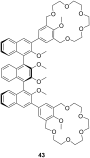
Figure 25: Chiral bis-crown receptor 43 with a meso-ternaphthalene backbone.

Figure 26: Chromogenic pH-dependent bis-crown chemosensor 44 for diamines.

Figure 27: Triamine guests for binding to receptor 44.

Figure 28: Chiral bis-crown phenolphthalein chemosensors 46.

Figure 29: Crown ether amino acid 47.

Figure 30: Luminescent receptor 48 for bis-alkylammonium guests.

Figure 31: Luminescent CEAA (49a), a bis-CEAA receptor for amino acids (49b) and the structure of lysine bindi...

Figure 32: Luminescent CEAA tripeptide for binding small peptides.

Figure 33: Bis crown ether 51a self assembles co-operatively with C60-ammonium ion 51b.

Figure 34: Triptycene-based macrotricyclic dibenzo-[24]-crown-8 ether host 52 and guests.

Figure 35: Copper imido diacetic acid azacrown receptor 53a and the suggested His-Lys binding motif; a copper ...

Figure 36: Urea (54) and thiourea (55) benzo crown receptor for transport and extraction of amino acids.

Figure 37: Crown pyryliums ion receptors 56 for amino acids.

Figure 38: Ditopic sulfonamide bridged crown ether receptor 57.

Figure 39: Luminescent peptide receptor 58.

Figure 40: Luminescent receptor 59 for the detection of D-glucosamine hydrochloride in water/ethanol and lumin...

Figure 41: Guanidinium azacrown receptor 61 for simple amino acids and ditopic receptor 62 with crown ether an...

Figure 42: Chiral bicyclic guanidinium azacrown receptor 63 and similar receptor 64 for the enantioselective t...

Figure 43: Receptors for zwitterionic species based on luminescent CEAAs.

Figure 44: 1,10-Azacrown ethers with sugar podand arms and the anticancer agent busulfan.

Figure 45: Benzo-18-crown-6 modified β-cyclodextrin 69 and β-cyclodextrin functionalized with diaza-18-crown-6...

Figure 46: Receptors for colorimetric detection of primary and secondary ammonium ions.

Figure 47: Porphyrine-crown-receptors 72.

Figure 48: Porphyrin-crown ether conjugate 73 and fullerene-ammonium ion guest 74.

Figure 49: Calix[4]arene (75a), homooxocalix[4]arene (75b) and resorcin[4]arene (75c) compared (R = H, alkyl c...

Figure 50: Calix[4]arene and ammonium ion guest (R = H, alkyl, OAcyl etc.), possible binding sites; A: co-ordi...

Figure 51: Typical guests for studies with calixarenes and related molecules.
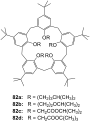
Figure 52: Lower rim modified p-tert-butylcalix[5]arenes 82.

Figure 53: The first example of a water soluble calixarene.

Figure 54: Sulfonated water soluble calix[n]arenes that bind ammonium ions.
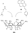
Figure 55: Displacement assay for acetylcholine (3) with a sulfonato-calix[6]arene (84b).

Figure 56: Amino acid inclusion in p-sulfonatocalix[4]arene (84a).

Figure 57: Calixarene receptor family 86 with upper and lower rim functionalization.

Figure 58: Calix[6]arenes 87 with one carboxylic acid functionality.
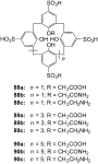
Figure 59: Sulfonated calix[n]arenes with mono-substitution at the lower rim systematically studied on their r...

Figure 60: Cyclotetrachromotropylene host (91) and its binding to lysine (81c).

Figure 61: Calixarenes 92 and 93 with phosphonic acids groups.

Figure 62: Calix[4]arene tetraphosphonic acid (94a) and a double bridged analogue (94b).

Figure 63: Calix[4]arene tetraphosphonic acid ester (92c) for surface recognition experiments.

Figure 64: Calixarene receptors 95 with α-aminophosphonate groups.

Figure 65: A bridged homocalix[3]arene 95 and a distally bridged homocalix[4]crown 96.

Figure 66: Homocalix[3]arene ammonium ion receptor 97a and the Reichardt’s dye (97b) for colorimetric assays.

Figure 67: Chromogenic diazo-bridged calix[4]arene 98.

Figure 68: Calixarene receptor 99 by Huang et al.

Figure 69: Calixarenes 100 reported by Parisi et al.

Figure 70: Guest molecules for inclusion in calixarenes 100: DAP × 2 HCl (101a), APA (101b) and Lys-OMe × 2 HC...

Figure 71: Different N-linked peptido-calixarenes open and with glycol chain bridges.

Figure 72: (S)-1,1′-Bi-2-naphthol calixarene derivative 104 published by Kubo et al.

Figure 73: A chiral ammonium-ion receptor 105 based on the calix[4]arene skeleton.

Figure 74: R-/S-phenylalaninol functionalized calix[6]arenes 106a and 106b.

Figure 75: Capped homocalix[3]arene ammonium ion receptor 107.

Figure 76: Two C3 symmetric capped calix[6]arenes 108 and 109.

Figure 77: Phosphorous-containing rigidified calix[6]arene 110.

Figure 78: Calix[6]azacryptand 111.

Figure 79: Further substituted calix[6]azacryptands 112.

Figure 80: Resorcin[4]arene (75c) and the cavitands (113).

Figure 81: Tetrasulfonatomethylcalix[4]resorcinarene (114).
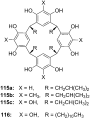
Figure 82: Resorcin[4]arenes (115a/b) and pyrogallo[4]arenes (115c, 116).
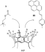
Figure 83: Displacement assay for acetylcholine (3) with tetracyanoresorcin[4]arene (117).

Figure 84: Tetramethoxy resorcinarene mono-crown-5 (118).

Figure 85: Components of a resorcinarene based displacement assay for ammonium ions.

Figure 86: Chiral basket resorcin[4]arenas 121.

Figure 87: Resorcinarenes with deeper cavitand structure (122).

Figure 88: Resorcinarene with partially open deeper cavitand structure (123).

Figure 89: Water-stabilized deep cavitands with partially structure (124, 125).
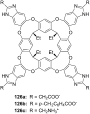
Figure 90: Charged cavitands 126 for tetralkylammonium ions.

Figure 91: Ditopic calix[4]arene receptor 127 capped with glycol chains.

Figure 92: A calix[5]arene dimer for diammonium salt recognition.

Figure 93: Calixarene parts 92c and 129 for the formation molecular capsules.
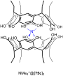
Figure 94: Encapsulation of a quaternary ammonium cation by two resorcin[4]arene molecules (NMe4+@[75c]2 × Cl−...

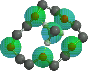
Figure 95: Encapsulation of a quaternary ammonium cation by six resorcin[4]arene molecules (NMe3D+@[130]6 × Cl−...

Figure 96: Structure and schematic of cucurbit[6]uril (CB[6], 131a).
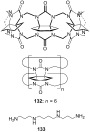
Figure 97: Cyclohexanocucurbit[6]uril (CB′[6], 132) and the guest molecule spermine (133).

Figure 98: α,α,δ,δ-Tetramethylcucurbit[6]uril (134).

Figure 99: Structure of the cucurbituril-phthalhydrazide analogue 135.

Figure 100: Organic cavities for the displacement assay for amine differentiation.

Figure 101: Displacement assay methodology for diammonium- and related guests involving cucurbiturils and some ...

Figure 102: Nor-seco-Cucurbituril (±)-bis-ns-CB[6] (140) and guest molecules.

Figure 103: The cucurbit[6]uril based complexes 141 for chiral discrimination.
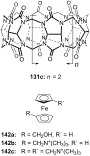
Figure 104: Cucurbit[7]uril (131c) and its ferrocene guests (142) opposed.

Figure 105: Cucurbit[7]uril (131c) guest inclusion and representative guests.

Figure 106: Cucurbit[7]uril (131c) binding to succinylcholine (145) and different bis-ammonium and bis-phosphon...

Figure 107: Paraquat-cucurbit[8]uril complex 149.
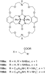
Figure 108: Gluconuril-based ammonium receptors 150.
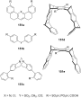
Figure 109: Examples of clefts (151a), tweezers (151b, 151c, 151d) and clips (151e).

Figure 110: Kemp’s triacid (152a), on example of Rebek’s receptors (152b) and guests.

Figure 111: Amino acid receptor (154) by Rebek et al.

Figure 112: Hexagonal lattice designed hosts by Bell et al.

Figure 113: Bell’s amidinium receptor (156) and the amidinium ion (157).
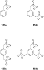
Figure 114: Aromatic phosphonic acids.

Figure 115: Xylene phosphonates 159 and 160a/b for recognition of amines and amino alcohols.
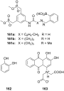
Figure 116: Bisphosphonate recognition motif 161 for a colorimetric assay with alizarin complexone (163) for ca...

Figure 117: Bisphosphonate/phosphate clip 164 and bisphosphonate cleft 165.

Figure 118: N-Methylpyrazine 166a, N-methylnicotinamide iodide (166b) and NAD+ (166c).

Figure 119: Bisphosphate cavitands.
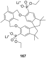
Figure 120: Bisphosphonate 167 of Schrader and Finocchiaro.
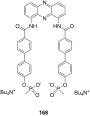
Figure 121: Tweezer 168 for noradrenaline (80b).

Figure 122: Different tripods and heparin (170).
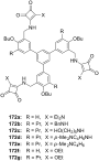
Figure 123: Squaramide based receptors 172.
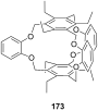
Figure 124: Cage like NH4+ receptor 173 of Kim et al.

Figure 125: Ammonium receptors 174 of Chin et al.

Figure 126: 2-Oxazolin-based ammonium receptors 175a–d and 176 by Ahn et al.

Figure 127: Racemic guest molecules 177.

Figure 128: Tripods based on a imidazole containing macrocycle (178) and the guest molecules employed in the st...

Figure 129: Ammonium ion receptor 180.

Figure 130: Tetraoxa[3.3.3.3]paracyclophanes 181 and a cyclophanic tetraester (182).

Figure 131: Peptidic bridged paraquat-cyclophane.
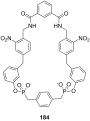
Figure 132: Shape-selective noradrenaline host.

Figure 133: Receptor 185 for binding of noradrenaline on surface layers from Schrader et al.

Figure 134: Tetraphosphonate receptor for binding of noradrenaline.

Figure 135: Tetraphosphonate 187 of Schrader and Finocchiaro.

Figure 136: Zinc-Porphyrin ammonium-ion receptors 188 and 189 of Mizutani et al.
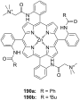
Figure 137: Zinc porphyrin receptor 190.

Figure 138: Zinc porphyrin receptors 191 capable of amino acid binding.

Figure 139: Zinc-porphyrins with amino acid side chains for stereoinduction.

Figure 140: Bis-zinc-bis-porphyrin based on Tröger’s base 193.

Figure 141: BINAP-zinc-prophyrin derivative 194 and it’s guests.

Figure 142: Bisaryl-linked-zinc-porphyrin receptors.
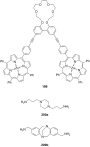
Figure 143: Bis-zinc-porphyrin 199 for diamine recognition and guests.

Figure 144: Bis-zinc-porphyrin crown ether 201.

Figure 145: Bis-zinc-porphyrin 202 for stereodiscrimination (L = large substituent; S = small substituent).

Figure 146: Bis-zinc-porphyrin[3]rotaxane and its copper complex and guests.

Figure 147: Dien-bipyridyl ligand 206 for co-ordination of two metal atoms.

Figure 148: The ligand and corresponding tetradentate co-complex 207 serving as enantioselective receptor for a...

Figure 149: Bis(oxazoline)–copper(II) complex 208 for the recognition of amino acids in aqueous solution.

Figure 150: Zinc-salen-complexes 209 for the recognition tertiary amines.

Figure 151: Bis(oxazoline)–copper(II) 211 for the recognition of amino acids in aqueous solution.

Figure 152: Zn(II)-complex of a C2 terpyridine crown ether.

Figure 153: Displacement assay and receptor for aspartate over glutamate.

Figure 154: Chiral complex 214 for a colorimetric displacement assay for amino acids.

Figure 155: Metal complex receptor 215 with tripeptide side arms.

Figure 156: A sandwich complex 216 and its displaceable dye 217.

Figure 157: Lanthanide complexes 218–220 for amino acid recognition.
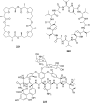
Figure 158: Nonactin (221), valinomycin (222) and vancomycin (223).

Figure 159: Monesin (224a) and a chiral analogue for enantiodiscrimination of ammonium guests (224b).

Figure 160: Chiral podands (226) compared to pentaglyme-dimethylether (225) and 18-crown-6 (4).

Figure 161: Lasalocid A (228).

Figure 162: Lasalocid derivatives (230) of Sessler et al.

Figure 163: The Coporphyrin I tetraanion (231).

Figure 164: Linear and cyclic peptides for ammonium ion recognition.

Figure 165: Cyclic and bicyclic depsipeptides for ammonium ion recognition.
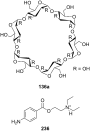
Figure 166: α-Cyclodextrin (136a) and novocaine (236).
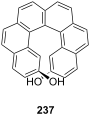
Figure 167: Helical diol receptor 237 by Reetz and Sostmann.

Figure 168: Ammonium binding spherand by Cram et al. (238a) and the cyclic[6]metaphenylacetylene 238b in compar...

Figure 169: Receptor for peptide backbone and ammonium binding (239).

Figure 170: Anion sensor principle with 3-hydroxy-2-naphthanilide of Jiang et al.

Figure 171: 7-bromo-3-hydroxy-N-(2-hydroxyphenyl)naphthalene 2-carboxamide (241) and its amine binding.

Figure 172: Naturally occurring catechins with affinity to quaternary ammonium ions.

Figure 173: Spiropyran (244) and merocyanine form (244a) of the amino acid receptors of Fuji et al.

Figure 174: Coumarin aldehyde (245) and its iminium species with amino acid bound (245a) by Glass et al.
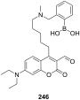
Figure 175: Coumarin aldehyde appended with boronic acid.

Figure 176: Quinolone aldehyde dimers by Glass et al.

Figure 177: Chromogenic ammonium ion receptors with trifluoroacetophenone recognition motifs.

Figure 178: Chromogenic ammonium ion receptor with trifluoroacetophenone recognition motif bound on different m...
Concise methods for the synthesis of chiral polyoxazolines and their application in asymmetric hydrosilylation
- Wei Jie Li,
- Zun Le Xu and
- Sheng Xiang Qiu
Beilstein J. Org. Chem. 2010, 6, No. 29, doi:10.3762/bjoc.6.29
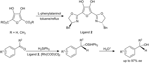
- C21H27N3O3: C, 68.27; H, 7.37; N, 11.37. Found: C, 67.98; H, 7.63; N, 11.56. (+)-N,N,N′,N′-Tetrakis{[4-(R)-ethyloxazolin-2-yl]methyl}ethylenediamine (6) Ethylenediaminetetraacetic acid (1.17 g, 4.0 mmol), (R)-2-amino-1-butanol (1.57 g, 17.6 mmol) and toluene (40 mL) were added to a three-neck flask with a


Convergent syntheses of LeX analogues
- An Wang,
- Jenifer Hendel and
- France-Isabelle Auzanneau
Beilstein J. Org. Chem. 2010, 6, No. 17, doi:10.3762/bjoc.6.17
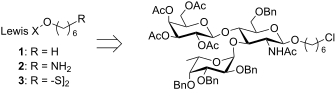
- group (NaCNBH3, HCl·Et2O) to yield acceptor 6. The triacetate 15 was also converted in seven steps to acceptor 5. The phthalimido group was first removed (ethylenediamine, EtOH) and the free amine acetylated. Zemplén deacetylation was followed by conversion of the triol to the 4,6-benzylidene acetal 18

Graphical Abstract

Figure 1: Structure of Lex analogues 1–3.

Figure 2: Monosaccharide glycosyl acceptors (4–6) and donors (7–9) used in this study.

Scheme 1: Synthesis of monosaccharide glycosyl acceptors 4–6.

Scheme 2: Synthesis of the galactosyl donor 8.
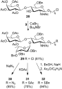
Scheme 3: Convergent synthesis of trisaccharides 29–32.

Scheme 4: Proposed mechanism for the desulfurization of thioacetate 31 under dissolving metal conditions.
Synthesis and binding studies of two new macrocyclic receptors for the stereoselective recognition of dipeptides
- Ana Maria Castilla,
- M. Morgan Conn and
- Pablo Ballester
Beilstein J. Org. Chem. 2010, 6, No. 5, doi:10.3762/bjoc.6.5
- amide groups (ΔΔG0 (ethylenediamine-succinamide) = −2.35 kcal/mol). The calculated stability constants are, in general, lower than the values expected for a complex that can be stabilized by an array of not adjacent four hydrogen bonds in chloroform solution (K ≈ 104 M−1). The stability constant values
- for the hydrogen-bonding pattern DAAD instead of ADAD when n = 2 (ΔΔG0 (succinamide-ethylenediamine) = −0.92 kcal/mol) but selects the hydrogen-bonding pattern ADAD when n = 1 (ΔΔG0 (Gly-malonamide) = −0.90 kcal/mol). Surprisingly, linear receptors 15 and 17 exhibited higher levels of

Graphical Abstract

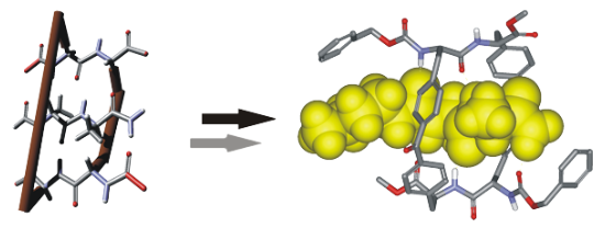
Figure 1: Schematic representation of the design of a host–guest complex based on antiparallel β-sheet geomet...

Figure 2: Molecular structures of the two designed receptors 1 and 2 having different relative orientations o...
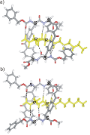
Figure 3: CAChe minimized structures for the “endo” complexes formed between receptors 1 (a) and 2 (b) and th...

Scheme 1: Synthesis of tetraprotected bis(alanyl)benzophenones 3 from L-phenylalanine 7.
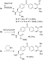
Scheme 2: Deprotection reactions of bis(alanyl)benzophenone units 3.

Scheme 3: Synthesis of the linear tetrapeptides 15 and 17 as mixtures of diastereoisomers.
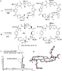
Figure 4: a) Molecular structures of the two major diastereoisomers of the cyclic receptors obtained from the...
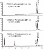
Figure 5: Reverse-phase HPLC chromatograms of the purified fraction obtained from macrocyclization reactions ...

Figure 6: Variable-temperature 1H NMR experiments of 1 in chloroform-d solution. The proton signals that appe...

Figure 7: Small fraction of the columnar arrangement observed in solid-state packing of receptor 1. Two adjac...
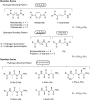
Figure 8: Molecular structures of the guests used in the binding experiments.

Figure 9: Selected region of the variable-concentration 1H NMR spectra acquired using chloroform-d solutions ...
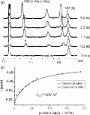
Figure 10: a) Selected region of a series 1H NMR spectra acquired during titration of receptor 2 with n-C6H13-...
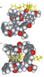
Figure 11: CAChe minimized structures for two possible binding geometries, a) exo and b) endo complexes formed...
Prediction of reduction potentials from calculated electron affinities for metal-salen compounds
- Sarah B. Bateni,
- Kellie R. England,
- Anthony T. Galatti,
- Handeep Kaur,
- Victor A. Mendiola,
- Alexander R. Mitchell,
- Michael H. Vu,
- Benjamin F. Gherman and
- James A. Miranda
Beilstein J. Org. Chem. 2009, 5, No. 82, doi:10.3762/bjoc.5.82
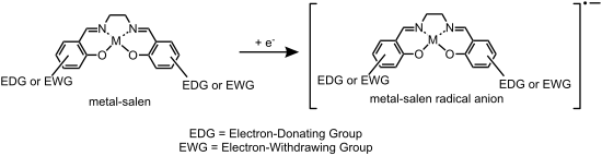
- condensation of the appropriate substituted salicylaldehyde with ethylenediamine. The reaction was allowed to reflux for 2 h before the crude salen ligand was recrystallized in 95% ethanol. Each salen ligand was characterized by IR and NMR spectroscopy. Second, the appropriate metal acetate and the salen

Graphical Abstract

Figure 1: Training set of 19 metal-salens.

Figure 2: Correlation between electron affinity (EA) and Hammett σp parameter in the training set (R2 = 0.76,...

Figure 3: Correlation between Epc and EA for the Ni, Co, and Cu training set metal-salens (R2 = 0.93, 0.17 (0...

Figure 4: Comparison of experimental and predicted Epc for all training set metal-salens.

Figure 5: Test set of 14 metal-salens.
(−)-Complanine, an inflammatory substance of marine fireworm: a synthetic study
- Kazuhiko Nakamura,
- Yu Tachikawa and
- Daisuke Uemura
Beilstein J. Org. Chem. 2009, 5, No. 12, doi:10.3762/bjoc.5.12
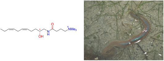
- Discussion Our synthesis started from the known compound 3 [5][6] that could be derived from (R)-malic acid, (R)-2, in three steps (1. BH3·SMe2; 2. cat. TsOH, Et2CO; 3. TsCl, pyridine) (Scheme 1). The resultant tosylate 3 was treated with lithium acetylide ethylenediamine complex to give the terminal
- complanata (body length 10 cm). Total synthesis of complanine. Keys: a) 1. BH3·SMe2 (71%); 2. cat. TsOH, Et2CO (59%); 3. TsCl, pyridine (80%) [5][6]; b) lithium acetylide ethylenediamine complex (1.2 equiv), DMSO, rt, 3 h (51%); c) 1-iodopent-2-yne (2.0 equiv), EtMgBr (1.6 equiv), CuI (cat.), THF, 0 °C to rt

Graphical Abstract

Figure 1: Structure of (R)-(−)-complanine.

Figure 2: Marine fireworm Eurythoe complanata (body length 10 cm).

Scheme 1: Total synthesis of complanine. Keys: a) 1. BH3·SMe2 (71%); 2. cat. TsOH, Et2CO (59%); 3. TsCl, pyri...
Hydrogenation of aromatic ketones, aldehydes, and epoxides with hydrogen and Pd(0)EnCat™ 30NP
- Steven V. Ley,
- Angus J. P. Stewart-Liddon,
- David Pears,
- Remedios H. Perni and
- Kevin Treacher
Beilstein J. Org. Chem. 2006, 2, No. 15, doi:10.1186/1860-5397-2-15
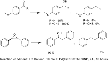
- that different side reactions can take place like aromatic ring hydrogenation, as well as hydrogenolysis of the produced alcohol to the hydrocarbon derivative. [5][6] Some of these problems have been circumvented by adding ethylenediamine, [7] although this can make isolation of the product and