Abstract
We present a quantitative study of the current–voltage characteristics (CVC) of SFIFS Josephson junctions (S = bulk superconductor, F = metallic ferromagnet, I = insulating barrier) with weak ferromagnetic interlayers in the diffusive limit. The problem is solved in the framework of the nonlinear Usadel equations. We consider the case of a strong tunnel barrier such that the left SF and the right FS bilayers are decoupled. We calculate the density of states (DOS) in SF bilayers using a self-consistent numerical method. Then we obtain the CVC of corresponding SFIFS junctions, and discuss their properties for different set of parameters including the thicknesses of ferromagnetic layers, the exchange field, and the magnetic scattering time. We observe an anomalous nonmonotonic CVC in case of weak ferromagnetic interlayers, which we attribute to DOS energy dependencies in the case of small exchange fields in the F layers.
Introduction
It is well known that superconductivity and ferromagnetism are two competing antagonistic orders. In superconductors (S) electrons form Cooper pairs with opposite spins and momenta, while in ferromagnetic metals (F) electron spins tend to align in parallel. Nevertheless, it is possible to combine S and F layers in one hybrid structure, which leads to the observation of many striking phenomena. The reason is the superconducting proximity effect, i.e., the superconducting correlations leakage into a ferromagnetic metal due to Andreev reflection [1-7]. As a consequence, the real part of the pair wave function exhibits damped oscillatory behavior in a ferromagnetic metal. Hence, since the oscillations are spatially dependent, it is possible to realize a transition from “0” to “π” phase states in S/F/S structures upon changing the F layer thickness [1]. The proximity effect is characterized by the two length scales of decay and oscillations of the real part of the pair wave function in a ferromagnetic layer, ξf1 and ξf2, correspondingly [1]. If we consider the exchange field h as the only important parameter of a ferromagnetic material, both lengths are equal to ![[Graphic 1]](/bjnano/content/inline/2190-4286-11-19-i17.svg?max-width=637&scale=1.18182) , where Df is the diffusion constant in the ferromagnetic metal.
, where Df is the diffusion constant in the ferromagnetic metal.
The existence of such phenomena enables the creation of so-called Josephson π junctions with a negative critical current [1,2]. Oscillations of the pair wave function in the F layer leads to several interesting phenomena in S/F/(S) systems, including nonmonotonic critical temperature dependence [8-12], Josephson critical current oscillations [13-41], and density of states (DOS) oscillations [42-45]. S/F hybrid structures have many promising applications in, e.g., single-flux quantum circuits [46,47], spintronic devices [48], memory elements [49-58] and spin-valves [59-65], magnetoelectronics [66-68], qubits [69], artificial neural networks [70], microrefrigerators [71,72], and low-temperature sensitive electron thermometers [73].
However, junctions with a ferromagnetic interlayer as well as other normal metal junctions (for example, SFNFS), proposed as elements of novel superconducting nanoelectronics, have limited applicability since such junctions have low resistance values [74,75]. This situation is resolved by addition of an insulating barrier (I) yielding a SFIFS layer sequence, which allows one to realize much larger values of the product IcRn, where Ic is the critical current of the junction and Rn its normal state resistance [36-38]. Recently, SIFS junctions attracted much attention and have been extensively studied both experimentally [32-41] and theoretically [23,45,76-80]. For instance, the current–voltage characteristics (CVC) of SIFS Josephson junctions with a strong insulating layer were studied in [45]. They exhibit interesting nonmonotonic behavior for weak ferromagnetic interlayers, i.e., small enough exchange fields. The reason for this behavior is the shape of the density of states in the F layer. At small exchange fields the decay length of superconducting correlations in the ferromagnetic material, ξh, is large enough, which leads to profound variations of the superconducting density of states in the F layer as a function of the energy and results in a corresponding CVC behavior. With an increase of the exchange field the ξh decreases, which suppresses the superconducting correlations in the F layer and makes the SIFS CVC similar to the I–V curve of the FIS junction.
In this paper we study the current–voltage characteristics of SFIFS Josephson junctions with two ferromagnetic interlayers. SFIFS structures were also proposed for various applications in memory elements [56-58], single-flux quantum circuits [47], and as injectors in superconductor–ferromagnetic transistors [81-84], which can be used as amplifiers for memory, digital, and RF applications. In this work we study the current–voltage characteristics of a SFIFS junction as shown below in Figure 1. We present a quantitative model of the quasiparticle current in SFIFS junctions for different sets of parameters characterizing the ferromagnetic interlayers. In case of weak ferromagnetic metals we find an anomalous nonmonotonic shape of the current–voltage characteristics at subgap voltages and compare the results with the CVC of SIFS junctions [45]. We ascribe this behavior to DOS energy dependencies in case of small exchange fields in the F layers. The shape is smeared if we include a finite magnetic scattering rate. The anomalous nonmonotonic shape of the current–voltage characteristics of SFIFS junctions with weak ferromagnetic layers looks similar to the fine structures of quasiparticle currents, recently obtained experimentally on similar systems [82-85].
The paper is organized as follows. In the first section (“Model”) we formulate the theoretical model and basic equations and introduce the self-consistent numerical iterative method for calculating the density of states in S/F bilayers. In the next section (“Results and Discussion”) we present and discuss the results for the density of states in S/F bilayers in case of subgap values of the exchange field and the current–voltage characteristics of SFIFS junctions. Finally we summarize the results in the last section (“Conclusion”).
Model
In this section we present the theoretical model we use in our studies. The geometry of the considered system is depicted in Figure 1. It consists of two superconducting electrodes and a pair of ferromagnetic interlayers, with thicknesses df1 and df2. The system contains three interfaces: two S/F (superconductor/ferromagnet) boundaries and one tunnel F-I-F interface. Each of these interfaces is described by the dimensionless parameter γBj = RBjσn/ξn (j = 0, 1, 2), which is proportional to the resistance RBj across the interface [86-88]. Here σn is the conductivity of the F layer and ![[Graphic 2]](/bjnano/content/inline/2190-4286-11-19-i18.svg?max-width=637&scale=1.18182) is the coherence length, where Tc is the critical temperature of the superconductor S (here and below we assume ℏ = kB = 1). In this paper we consider the diffusive limit, when the elastic scattering length
is the coherence length, where Tc is the critical temperature of the superconductor S (here and below we assume ℏ = kB = 1). In this paper we consider the diffusive limit, when the elastic scattering length ![[Graphic 3]](/bjnano/content/inline/2190-4286-11-19-i19.svg?max-width=637&scale=1.18182) is much smaller than the characteristic decay length of the real part of the pair wave function in the ferromagnet, ξf1, which we introduce later in Equation 13 and Equation 14. We assume that the S/F interfaces are not magnetically active. We also neglect the nonequilibrium effects [89-91] and use the Matsubara Green’s functions technique, which has been developed to describe many-body systems in equilibrium at finite temperature [92].
is much smaller than the characteristic decay length of the real part of the pair wave function in the ferromagnet, ξf1, which we introduce later in Equation 13 and Equation 14. We assume that the S/F interfaces are not magnetically active. We also neglect the nonequilibrium effects [89-91] and use the Matsubara Green’s functions technique, which has been developed to describe many-body systems in equilibrium at finite temperature [92].
![[2190-4286-11-19-1]](/bjnano/content/figures/2190-4286-11-19-1.png?scale=2.0&max-width=1024&background=FFFFFF)
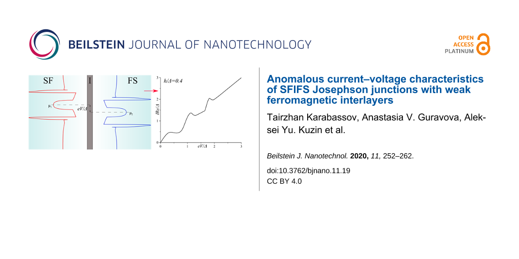
Figure 1: Schematic representation of the SFIFS hybrid structure (here S is a superconductor, F is a ferromagnetic metal and I is an insulating barrier). The thicknesses of the ferromagnetic interlayers are df1 and df2, correspondingly. The transparency of the left S/F interface is characterized by the parameter γB1, while the transparency of the right F/S interface is characterized by the parameter γB2. Both parameters γB1, γB2 ≪ 1, which corresponds to transparent metallic interfaces. The insulating barrier between the left and right interfaces (I) is described by γB0 ≫ 1.
Figure 1: Schematic representation of the SFIFS hybrid structure (here S is a superconductor, F is a ferromag...
In our model the tunneling barrier is located between two F layers at x = 0 (Figure 1), whereas the other interfaces at x = −df1 and x = df2 are identical and transparent. This case corresponds to γB1 = γB2 ≪ 1 and γB0 ≫ 1. In case of a sufficiently strong tunnel barrier (γB0 ≫ 1), the two S/F bilayers in the SFIFS junction are decoupled, i.e., the amplitudes of two-electron processes between left and right F layers are negligibly small. Hence, the quasiparticle current through the SFIFS junction, biased by the voltage eV, can be calculated by using the Werthamer formula [93],
![[2190-4286-11-19-i1]](/bjnano/content/inline/2190-4286-11-19-i1.svg?max-width=590&scale=1.18182)
where Nf1,2(E) are the densities of states (DOS) in the corresponding ferromagnetic layer at x = 0, f(E)= [1 + eE/T]−1 is the Fermi–Dirac distribution function, and R = RB0 is the resistance across the F-I-F interface. Both densities of states Nf1,2(E) are normalized to their values in the normal state.
In order to obtain the densities of states in ferromagnetic layers, Nf1,2(E), we use a self-consistent two-step iterative procedure, described below. As far as γB0 ≫ 1, we can neglect the influence of the right F layer on the density of states in the left S/F bilayer and vice versa (see Figure 1). Thus we need to obtain the DOS at the outer border of each S/F bilayer. That can be done by solving the Usadel equations in the S/F bilayer system [94].
In the following, we use the θ-parameterizations of normal (G = cos θ) and anomalous (F = sin θ) Green’s functions and write the Usadel equations in the F layers in the form [94,95],
![[2190-4286-11-19-i2]](/bjnano/content/inline/2190-4286-11-19-i2.svg?max-width=590&scale=1.18182)
where the positive and negative signs correspond to the spin-up (“↑”) and spin-down (“↓”) states, respectively. In terms of the electron fermionic operators ψ↑(↓) the spin-up state corresponds to the anomalous Green’s function F↑ ∼ ⟨ ψ↑ψ↓⟩, while spin-down state corresponds to F↓ ∼ ⟨ψ↓ψ↑⟩. The expressions ω = 2πT(n + 1/2) are the Matsubara frequencies, where n = 0, ±1, ±2, …, and h is the exchange field in the ferromagnet. The scattering times are labeled here as τz, τx, and τso, where τz(x) corresponds to the magnetic scattering parallel (perpendicular) to the quantization axis, and τso is the spin–orbit scattering time [96-99].
Assuming a strong uniaxial anisotropy in ferromagnetic materials, in which case there is no coupling between spin-up and spin-down electron populations, we neglect τx (τx−1 ≈ 0). We also assume the ferromagnets to have a weak spin–orbit coupling and thus neglect the spin–orbit scattering time τso. After taking into account all the assumptions, the Usadel equations in the ferromagnetic layers for different spin states can be written as
![[2190-4286-11-19-i3]](/bjnano/content/inline/2190-4286-11-19-i3.svg?max-width=590&scale=1.18182)
where τm ≡ τz is the magnetic scattering time. In the superconducting layer S the Usadel equation reads [94]
![[2190-4286-11-19-i4]](/bjnano/content/inline/2190-4286-11-19-i4.svg?max-width=590&scale=1.18182)
Here Ds is the diffusion coefficient in the S layer and Δ(x) is the pair potential in the superconductor. We note that Δ(x) vanishes in the F layer.
Equation 3 and Equation 4 must be supplemented with corresponding boundary conditions. At the S/F interfaces we apply the Kupriyanov–Lukichev boundary conditions. For example, at the left S/F interface they are written as [86],
![[2190-4286-11-19-i5]](/bjnano/content/inline/2190-4286-11-19-i5.svg?max-width=590&scale=1.18182)
![[2190-4286-11-19-i6]](/bjnano/content/inline/2190-4286-11-19-i6.svg?max-width=590&scale=1.18182)
Similar equations can be written at the right S/F interface at x = df2. Here γ = ξsσn/ξnσs, where σs is the conductivity of the S layer and ![[Graphic 4]](/bjnano/content/inline/2190-4286-11-19-i20.svg?max-width=637&scale=1.18182) is the superconducting coherence length. The parameter γ defines the strength of the inverse proximity effect, i.e., the suppression of superconductivity in the adjacent S layer by the ferromagnetic layer F. We consider the parameter γ to be relatively small γ ≪ 1, which corresponds to a rather weak suppression.
is the superconducting coherence length. The parameter γ defines the strength of the inverse proximity effect, i.e., the suppression of superconductivity in the adjacent S layer by the ferromagnetic layer F. We consider the parameter γ to be relatively small γ ≪ 1, which corresponds to a rather weak suppression.
To calculate the density of states in the S/F bilayer we should set the boundary conditions at the outer boundary of the ferromagnet (x = 0),
![[2190-4286-11-19-i7]](/bjnano/content/inline/2190-4286-11-19-i7.svg?max-width=590&scale=1.18182)
To complete the boundary problem we also set a boundary condition at x = ±∞,
![[2190-4286-11-19-i8]](/bjnano/content/inline/2190-4286-11-19-i8.svg?max-width=590&scale=1.18182)
where the Green’s functions acquire the well-known bulk BCS form. We notice that the density of states at x = ±∞ is given by standard BCS equation,
![[2190-4286-11-19-i9]](/bjnano/content/inline/2190-4286-11-19-i9.svg?max-width=590&scale=1.18182)
where Θ(x) is the Heaviside step function.
Finally the self-consistency equation for the superconducting order parameter takes the form,
![[2190-4286-11-19-i10]](/bjnano/content/inline/2190-4286-11-19-i10.svg?max-width=590&scale=1.18182)
Equations Equation 3–Equation 8 and Equation 10 represent a closed set of equations that should be solved self-consistently.
The density of states Nf1,2(E) normalized to the DOS in the normal state, can be written as
![[2190-4286-11-19-i11]](/bjnano/content/inline/2190-4286-11-19-i11.svg?max-width=590&scale=1.18182)
where Nfj↑(↓)(E) are the spin-resolved densities of states written in terms of the spectral angle θ,
![[2190-4286-11-19-i12]](/bjnano/content/inline/2190-4286-11-19-i12.svg?max-width=590&scale=1.18182)
To obtain Nf1,2, we use a self-consistent two-step iterative procedure [95,100-102]. In the first step we calculate the pair potential coordinate dependence Δ(x) using the self-consistency equation in the S layer (Equation 10). Then, by proceeding to the analytical continuation in Equation 3 and Equation 4 over the quasiparticle energy iω→E + i0 and using the Δ(x) dependence obtained in the previous step, we find the Green’s functions by repeating the iterations until convergency is reached.
The characteristic lengths of the decay and oscillations of the real part of the pair wave function in the ferromagnetic layer at the Fermi energy, ξf1,2, are given in our model by [45],
![[2190-4286-11-19-i13]](/bjnano/content/inline/2190-4286-11-19-i13.svg?max-width=590&scale=1.18182)
![[2190-4286-11-19-i14]](/bjnano/content/inline/2190-4286-11-19-i14.svg?max-width=590&scale=1.18182)
We see from these equations that with an increase of the magnetic scattering rate αm = 1/τmΔ the length of decay ξf1 decreases, while the length of oscillations ξf2 increases. In the absence of magnetic scattering ξf1 = ξf2 = ξh = ![[Graphic 5]](/bjnano/content/inline/2190-4286-11-19-i21.svg?max-width=637&scale=1.18182) .
.
Results and Discussion
In this section we present the results of the DOS energy dependencies in SF bilayers at the free boundary of the F layer for h ≤ Δ. The densities of states for h ≥ Δ were thoroughly discussed in [45]. Then we calculate the corresponding CVC of the SFIFS junction using the Werthamer formula (Equation 1). In the case of h ≤ Δ we obtain an interesting nonmonotonic behavior of the quasiparticle current, presented in a subsection below (“Current–voltage characteristics of SFIFS junctions”). At large exchange fields the decay length ξf2 of the real part of the pair wave function in the F layer becomes small (see Equation 13 and Equation 14), and the amplitude of DOS variations tends to zero. In this case the CVC of SFIFS junction tends to follow Ohm’s law for h ≫ Δ. The ferromagnetic materials with small exchange fields can be fabricated as discussed in [103]. We also note that the DOS at the end of an SF bilayer in case of a domain wall in the ferromagnetic layer was studied in [104].
Density of states in SF bilayers for h ≤ Δ
Figure 2 and Figure 3 show the DOS energy dependencies for different values of h ≤ Δ and for relatively thick F layers. In our calculations we fix the temperature at T = 0.1Tc, where Tc is the critical temperature of the superconductor S. In Figure 2 the characteristic “finger-like” shape of DOS is observed along with a minigap for df = 2ξn (Figure 2a,c). At larger df and/or at larger h the minigap closes (Figure 2c and Figure 3a,c)]. In the absence of magnetic scattering (αm = 1/τmΔ = 0) we can roughly estimate the critical value hc of the exchange field at which the minigap closes as [45]
![[2190-4286-11-19-i15]](/bjnano/content/inline/2190-4286-11-19-i15.svg?max-width=590&scale=1.18182)
where ETh is the Thouless energy and df is the thickness of the F layer in the SF bilayer (df1 or df2 for the left or right SF bilayer, respectively, in Figure 1). Since we consider subgap values of h, the minigap closes at rather large values of df in the absence of magnetic scattering.
![[2190-4286-11-19-2]](/bjnano/content/figures/2190-4286-11-19-2.png?scale=2.0&max-width=1024&background=FFFFFF)
Figure 2: DOS Nf(E) on the free boundary of the F layer in the FS bilayer obtained numerically for two cases: (a) in the absence of magnetic scattering, αm = 1/τmΔ = 0 (plots a and c) and in the case of finite magnetic scattering, i.e., plot b with αm = 0.1 and plot d with αm = 0.5. Parameters of the FS interface are γ = γB = 0.01, and T = 0.1Tc. Plots a, b: h = 0.1Δ; plots c, d: h = 0.3Δ. The black solid line corresponds to df = 2ξn, while the red dashed line corresponds to df = 3ξn.
Figure 2: DOS Nf(E) on the free boundary of the F layer in the FS bilayer obtained numerically for two cases:...
![[2190-4286-11-19-3]](/bjnano/content/figures/2190-4286-11-19-3.png?scale=2.0&max-width=1024&background=FFFFFF)
Figure 3: DOS Nf(E) on the free boundary of the F layer in the FS bilayer obtained numerically in the absence of magnetic scattering, αm = 1/τmΔ = 0 (plots a and c) and in the case of finite magnetic scattering, i.e., plot b with αm = 0.1 and plot d with αm = 0.5. Plots a, b: h = 0.5Δ; plots c, d: h = 0.7Δ. The black solid line corresponds to df = 2ξn, while the red dashed line corresponds to df = 3ξn.
Figure 3: DOS Nf(E) on the free boundary of the F layer in the FS bilayer obtained numerically in the absence...
After the minigap closes the DOS at the Fermi energy Nf(0) rapidly increases to values larger than unity with further increase of df and then it oscillates around unity while its absolute value exponentially approaches unity [45]. This is the well-known damped oscillatory behavior with the lengths of decay and oscillations given by Equation 13 and Equation 14, respectively. Figure 2b,d and Figure 3b,d show that stronger magnetic scattering leads to the minigap closing at smaller values of df. With the increase of αm = 1/τmΔ the period of oscillations increases (ξf2 in Equation 14 increases). At the same time the DOS variation amplitude becomes smaller and DOS features smear, since for larger αm the dumped exponential decay of oscillations occurs faster (ξf1 in Equation 13 decreases).
Finally, in Figure 4 we present plots for spin-resolved densities of states given by Equation 12 for both zero and finite magnetic scattering.
![[2190-4286-11-19-4]](/bjnano/content/figures/2190-4286-11-19-4.png?scale=2.0&max-width=1024&background=FFFFFF)
Figure 4: Spin-resolved DOS Nf↑(↓) on the free boundary of the F layer in the FS bilayer obtained numerically in the absence of magnetic scattering, αm = 0 (plots a and c) and in the case of finite magnetic scattering, i.e., plot b with αm = 0.1 and plot d with αm = 0.5. Plots a, b: h = 0.5Δ, df = 2ξn; plots c, d: h = 0.3Δ, df = 3ξn (c) and df = 2ξn (d). The black solid line corresponds to Nf(E), the red dashed line corresponds to Nf↑(E) and the blue dash-dotted line corresponds to Nf↓(E).
Figure 4: Spin-resolved DOS Nf↑(↓) on the free boundary of the F layer in the FS bilayer obtained numerically...
Current–voltage characteristics of SFIFS junctions
Using the densities of states Nf1,2(E) obtained in the subsection above, we calculate a set of quasiparticle current curves using Equation 1 for various values of parameters describing properties of ferromagnetic material, which include the thicknesses of the F layers, df1 and df2, the exchange field h, and the magnetic scattering rate αm. In our calculations we fix the temperature at T = 0.1Tc, where Tc is the critical temperature of the superconducting lead.
Figure 5 shows the CVC of a symmetric SFIFS junction, where df1 = df2 = df in the absence of magnetic scattering. For thin enough ferromagnetic interlayers, df/ξn = 0.5, and a small enough value of the exchange field, h = 0.5Δ, we observe CVC that resemble the I–V characteristic of a SNINS Josephson junction with a characteristic peak at eV ≈ 2Δ (see Figure 5a, solid black line) [101]. With an increase of the exchange field h this peak becomes smeared (see Figure 5b–d, solid black line). Increasing df and/or h produces a set of I–V curves among which the red dashed line in Figure 5d is the most interesting because it exhibits a nonmonotonic behavior. The reason of this atypical nonmonotonic behavior will be explained later.
![[2190-4286-11-19-5]](/bjnano/content/figures/2190-4286-11-19-5.png?scale=2.0&max-width=1024&background=FFFFFF)
Figure 5: Current–voltage characteristics of the symmetric (df1 = df2 = df) SFIFS junction in the absence of magnetic scattering for different values of exchange field h. The temperature T = 0.1Tc. In each graph the curves were calculated for different values of F layer thickness df, df = 0.5ξn (black solid line), df = 1.0ξn (red dashed line), df = 1.5ξn (blue dash-dotted line). The plots correspond to specific values of the exchange field h : plot (a) to h = 0.5Δ, (b) to h = 1.0Δ, (c) to h = 2.0Δ and (d) to h= 3.0Δ.
Figure 5: Current–voltage characteristics of the symmetric (df1 = df2 = df) SFIFS junction in the absence of ...
Figure 6 shows the current–voltage characteristics of SFIFS junctions at subgap values of the exchange field. We observe a nonmonotonic behavior for thick enough ferromagnetic layers at h ≤ Δ. Let us consider the CVC in Figure 6b, red dashed line. We can explain its behavior as well as any other nonmonotonic CVC behavior as the signature of the DOS energy dependence. The anomalous nonmonotonic I(V) dependence arises from the shape features of the densities of states, see Figure 7. In symmetric SFIFS junctions, Nf1(E) = Nf2(E) ≡ Nf(E) in Equation 1, which can be well approximated by taking T = 0 for small temperatures T ≪ Tc. In this case the Fermi–Dirac distribution function f(E) can be represented with the Heaviside step function Θ(−E) [and f(E − eV) with Θ(eV − E)]. As a result, the limits of integration in Equation 1 shrink to the interval [0, eV]. Hence, the current through the junction can be written as,
![[2190-4286-11-19-i16]](/bjnano/content/inline/2190-4286-11-19-i16.svg?max-width=590&scale=1.18182)
![[2190-4286-11-19-6]](/bjnano/content/figures/2190-4286-11-19-6.png?scale=2.0&max-width=1024&background=FFFFFF)
Figure 6: Current–voltage characteristics of a symmetric SFIFS junction for different values of the subgap exchange field h in the absence of magnetic scattering at a temperature T = 0.1Tc. In each graph the curves were calculated for different values of F layer thickness, df, df = 2ξn (black solid line) and df = 3ξn (red dashed line). The plots correspond to specific values of the subgap exchange field h: plot (a) to h = 0.1Δ, (b) to h = 0.3Δ, (c) to h = 0.5Δ and (d) to h = 0.7Δ.
Figure 6: Current–voltage characteristics of a symmetric SFIFS junction for different values of the subgap ex...
![[2190-4286-11-19-7]](/bjnano/content/figures/2190-4286-11-19-7.png?scale=2.0&max-width=1024&background=FFFFFF)
Figure 7: (a) CVC taken from Figure 6b, red dashed line, and visual explanation of the characteristic behavior of the quasiparticle current. (b–d) The DOS Nf(E − eV) and Nf(E) at particular values of eV revealing the origin of the current features in plot (a).
Figure 7: (a) CVC taken from Figure 6b, red dashed line, and visual explanation of the characteristic behavior of the ...
Using this expression, the origin of the nonmonotonic behavior of the CVC can be explained. At eV = 0 the upper limit of the integral in Equation 16 is zero and the current is zero. With the increase of the voltage, the current first increases linearly due to the broader region of integration as in Ohm’s law. The first feature that is shown in Figure 7a is a significant change in the slope of the current. Figure 7b shows the relative positions of the densities of states Nf(E − eV) and Nf(E) in this case, where almost no peak overlap can be seen, resulting in relatively small values of the integral in Equation 16. As we proceed to larger values of eV, we reach the first local maximum of the CVC, which corresponds to a maximum overlap of the densities of states Nf(E − eV) and Nf(E) at eV/Δ ≈ 1 (see Figure 7c). The second maximum of the quasiparticle current occurs at eV/Δ ≈ 1.68, which corresponds to a perfect DOS peak overlap at E/Δ ≈ 1 Figure 7d). For large enough values of the voltage eV, a product of the DOS Nf(E − eV) Nf(E) ≈ 1 and its integration does not produce any features. Thus, the CVC eventually coincides with Ohm’s law in this case. In fact any shape of a SFIFS I–V curve can be explained and understood in this way. We note that in this paper we present the densities of states in SF bilayers only for subgap values of the exchange field. For h ≥ Δ the DOS energy dependencies in SF bilayers can be found in [45].
Based on the properties of the density of states in FS bilayers we can see that even the tiny exchange field h can dramatically modify the current introducing anomalous nonmonotonic behavior in case of thick enough F layers (see Figure 5 and Figure 6). It is important to understand how the CVC of a SFIFS junction transforms as the exchange field h increases. In Figure 8 we demonstrate the plot of current–voltage characteristics calculated for a wide range of exchange field values h in the absence of magnetic scattering. From this plot it can be clearly seen that while for relatively small (subgap) values of the exchange field many interesting features appear in the structure of the current, at larger values of h these features are smeared and the CVC approaches Ohm’s law. Figure 9 shows the current–voltage characteristics in the case of an asymmetric SFIFS junction, i.e., when df1 ≠ df2 in the scase of zero magnetic scattering.
![[2190-4286-11-19-8]](/bjnano/content/figures/2190-4286-11-19-8.png?scale=2.0&max-width=1024&background=FFFFFF)
Figure 8: Current–voltage characteristics of a symmetric SFIFS junction in the absence of magnetic scattering for df = 3ξn. The temperature is T = 0.1Tc. The curves correspond to different values of h, from h = 0 to h = 1.2Δ with increments equal to 0.1Δ. The exchange field h = 0 corresponds to the case of a SNINS junction [101].
Figure 8: Current–voltage characteristics of a symmetric SFIFS junction in the absence of magnetic scattering...
![[2190-4286-11-19-9]](/bjnano/content/figures/2190-4286-11-19-9.png?scale=2.0&max-width=1024&background=FFFFFF)
Figure 9: Current–voltage characteristics of an asymmetric (df1 ≠ df2) SFIFS junction for different values of F layer thicknesses df1 and df2 (indicated in the plot) in the absence of magnetic scattering. The temperature is T = 0.1Tc, h = 0.5Δ (black solid line) and h = 1.0Δ (red dashed line). The labels show the values of F layer thicknesses df1 and df2 for which the curves were calculated: plot (a) corresponds to df1 = 0.5ξn and df2 = 1.0ξn, (b) to df1 = 0.5ξn and df2 = 2.0ξn, (c) to df1 = 1.0ξn and df2= 2.0ξn and (d) to df1 = 1.0ξn and df2 = 3.0ξn.
Figure 9: Current–voltage characteristics of an asymmetric (df1 ≠ df2) SFIFS junction for different values of...
In this section we also present the current–voltage characteristics of a SFIFS junction calculated in the presence of magnetic scattering for different values of the subgap exchange field h. Figure 10 illustrates the CVC in case of a finite magnetic scattering rate αm = 0.1. We consider both symmetric and asymmetric SFIFS junctions. The insets show the CVC in case of zero magnetic scattering. For very small h nonzero magnetic scattering leads to smearing of characteristic features of the current as shown in Figure 10. At larger subgap values of the exchange field h we see a “triple kink” structure (Figure 10c). For large enough values of αm the nonmonotonic behavior of the quasiparticle current will be smeared and the current approaches Ohm’s law. This is due to the fact that increasing αm the length of the superconducting correlations decay in the ferromagnetic layers decreases, see Equation 13, and the suppression of superconducting correlations in the F layers occurs faster.
![[2190-4286-11-19-10]](/bjnano/content/figures/2190-4286-11-19-10.png?scale=2.0&max-width=1024&background=FFFFFF)
Figure 10: Current–voltage characteristics of a SFIFS junction in the presence of magnetic scattering (αm = 0.1). The temperature is T = 0.1Tc. In plot (a) the black solid line corresponds to df1 = 1ξn, df2 = 2ξn, in plots (b) and (d) to df1 = df2 = 2ξn, and finally in plot (c) the black line corresponds to df1 = 0.5ξn, df2 = 2ξn. Plots (a, b): h = 0.1Δ; plot (c) and plot (d): h = 0.5Δ and h = 0.7Δ, respectively. The insets show the CVC in case of zero magnetic scattering.
Figure 10: Current–voltage characteristics of a SFIFS junction in the presence of magnetic scattering (αm = 0....
We can compare these results with the I–V characteristics of SIFS Josephson junctions [45]. In this case at zero magnetic scattering we may also observe the nonmonotonic behavior, but with only one peak [see Ref. [45], Figure 6 (c)]. In case of finite magnetic scattering the CVC has a “double kink” structure [see Ref. [45], Figure 7 (a, c)]. In SFIFS junctions the overlap of subgap DOS structures Nf1(E − eV) Nf2(E) in the integrand of the current equation, Equation 16, produce more complex behavior of the I–V characteristics.
We also notice that in recent experiments on SFIFS junctions as injectors of superconductor-ferromagnetic transistors some fine structures of the subgap quasiparticle current was observed [82-85], which looks similar to our theoretical results.
Conclusion
In this work we have presented the results of CVC calculations of a SFIFS junction for different set of parameters including the thicknesses of the ferromagnetic layers, df1 and df2, the exchange field, and the magnetic scattering time αm = 1/τmΔ. We considered the case of a strong insulating barrier such that the left SF and the right FS bilayers are decoupled. In order to obtain the current–voltage characteristics we first calculated the densities of states on the free boundary of the F layer in each SF bilayer utilizing an iterative self-consistent approach. Using the numerically obtained DOS we have derived the quasiparticle current of a SFIFS junction in the case of symmetric (df1 = df2) and asymmetric (df1 ≠ df2) structures. We have paid much attention to the case of a SFIFS junction with weak ferromagnetic interlayers with exchange fields h ≤ Δ. It was demonstrated that the CVC exhibits interesting and unusual features in this case, which can be ascribed to typical DOS behavior. We have provided a simple physical explanation for such anomalous CVC behavior. We have also illustrated how the CVC shape evolves as one increases the exchange field h. It should be emphasized that taking into account finite magnetic scattering leads to the smearing of characteristic features and, in particular cases, to a “triple kink” shape of the current.
References
-
Buzdin, A. I. Rev. Mod. Phys. 2005, 77, 935–976. doi:10.1103/revmodphys.77.935
Return to citation in text: [1] [2] [3] [4] -
Golubov, A. A.; Kupriyanov, M. Y.; Il’ichev, E. Rev. Mod. Phys. 2004, 76, 411–469. doi:10.1103/revmodphys.76.411
Return to citation in text: [1] [2] -
Bergeret, F. S.; Volkov, A. F.; Efetov, K. B. Rev. Mod. Phys. 2005, 77, 1321–1373. doi:10.1103/revmodphys.77.1321
Return to citation in text: [1] -
Demler, E. A.; Arnold, G. B.; Beasley, M. R. Phys. Rev. B 1997, 55, 15174–15182. doi:10.1103/physrevb.55.15174
Return to citation in text: [1] -
Ozaeta, A.; Vasenko, A. S.; Hekking, F. W. J.; Bergeret, F. S. Phys. Rev. B 2012, 86, 060509. doi:10.1103/physrevb.86.060509
Return to citation in text: [1] -
Bergeret, F. S.; Tokatly, I. V. Phys. Rev. Lett. 2013, 110, 117003. doi:10.1103/physrevlett.110.117003
Return to citation in text: [1] -
Bobkova, I. V.; Bobkov, A. M. Phys. Rev. B 2017, 95, 184518. doi:10.1103/physrevb.95.184518
Return to citation in text: [1] -
Jiang, J. S.; Davidović, D.; Reich, D. H.; Chien, C. L. Phys. Rev. Lett. 1995, 74, 314–317. doi:10.1103/physrevlett.74.314
Return to citation in text: [1] -
Izyumov, Y. A.; Proshin, Y. N.; Khusainov, M. G. Phys.-Usp. 2002, 45, 109–148. doi:10.1070/pu2002v045n02abeh001025
Return to citation in text: [1] -
Fominov, Y. V.; Chtchelkatchev, N. M.; Golubov, A. A. Phys. Rev. B 2002, 66, 014507. doi:10.1103/physrevb.66.014507
Return to citation in text: [1] -
Khaydukov, Y. N.; Vasenko, A. S.; Kravtsov, E. A.; Progliado, V. V.; Zhaketov, V. D.; Csik, A.; Nikitenko, Y. V.; Petrenko, A. V.; Keller, T.; Golubov, A. A.; Kupriyanov, M. Y.; Ustinov, V. V.; Aksenov, V. L.; Keimer, B. Phys. Rev. B 2018, 97, 144511. doi:10.1103/physrevb.97.144511
Return to citation in text: [1] -
Karabassov, T.; Stolyarov, V. S.; Golubov, A. A.; Silkin, V. M.; Bayazitov, V. M.; Lvov, B. G.; Vasenko, A. S. Phys. Rev. B 2019, 100, 104502. doi:10.1103/physrevb.100.104502
Return to citation in text: [1] -
Buzdin, A. I.; Bulaevskii, L. N.; Panyukov, S. V. JETP Lett. 1982, 35, 178.
Return to citation in text: [1] -
Vdovichev, S. N.; Nozdrin, Y. N.; Pestov, E. E.; Yunin, P. A.; Samokhvalov, A. V. JETP Lett. 2016, 104, 329–333. doi:10.1134/s0021364016170148
Return to citation in text: [1] -
Ryazanov, V. V.; Oboznov, V. A.; Rusanov, A. Y.; Veretennikov, A. V.; Golubov, A. A.; Aarts, J. Phys. Rev. Lett. 2001, 86, 2427–2430. doi:10.1103/physrevlett.86.2427
Return to citation in text: [1] -
Ryazanov, V. V.; Oboznov, V. A.; Veretennikov, A. V.; Rusanov, A. Y. Phys. Rev. B 2001, 65, 020501. doi:10.1103/physrevb.65.020501
Return to citation in text: [1] -
Blum, Y.; Tsukernik, A.; Karpovski, M.; Palevski, A. Phys. Rev. Lett. 2002, 89, 187004. doi:10.1103/physrevlett.89.187004
Return to citation in text: [1] -
Sellier, H.; Baraduc, C.; Lefloch, F.; Calemczuk, R. Phys. Rev. Lett. 2004, 92, 257005. doi:10.1103/physrevlett.92.257005
Return to citation in text: [1] -
Bauer, A.; Bentner, J.; Aprili, M.; Della Rocca, M. L.; Reinwald, M.; Wegscheider, W.; Strunk, C. Phys. Rev. Lett. 2004, 92, 217001. doi:10.1103/physrevlett.92.217001
Return to citation in text: [1] -
Bell, C.; Loloee, R.; Burnell, G.; Blamire, M. G. Phys. Rev. B 2005, 71, 180501. doi:10.1103/physrevb.71.180501
Return to citation in text: [1] -
Oboznov, V. A.; Bol’ginov, V. V.; Feofanov, A. K.; Ryazanov, V. V.; Buzdin, A. I. Phys. Rev. Lett. 2006, 96, 197003. doi:10.1103/physrevlett.96.197003
Return to citation in text: [1] -
Shelukhin, V.; Tsukernik, A.; Karpovski, M.; Blum, Y.; Efetov, K. B.; Volkov, A. F.; Champel, T.; Eschrig, M.; Löfwander, T.; Schön, G.; Palevski, A. Phys. Rev. B 2006, 73, 174506. doi:10.1103/physrevb.73.174506
Return to citation in text: [1] -
Vasenko, A. S.; Golubov, A. A.; Kupriyanov, M. Y.; Weides, M. Phys. Rev. B 2008, 77, 134507. doi:10.1103/physrevb.77.134507
Return to citation in text: [1] [2] -
Anwar, M. S.; Czeschka, F.; Hesselberth, M.; Porcu, M.; Aarts, J. Phys. Rev. B 2010, 82, 100501. doi:10.1103/physrevb.82.100501
Return to citation in text: [1] -
Khaire, T. S.; Khasawneh, M. A.; Pratt, W. P.; Birge, N. O. Phys. Rev. Lett. 2010, 104, 137002. doi:10.1103/physrevlett.104.137002
Return to citation in text: [1] -
Robinson, J. W. A.; Witt, J. D. S.; Blamire, M. G. Science 2010, 329, 59–61. doi:10.1126/science.1189246
Return to citation in text: [1] -
Baker, T. E.; Richie-Halford, A.; Icreverzi, O. E.; Bill, A. EPL 2014, 107, 17001. doi:10.1209/0295-5075/107/17001
Return to citation in text: [1] -
Alidoust, M.; Halterman, K. Phys. Rev. B 2014, 89, 195111. doi:10.1103/physrevb.89.195111
Return to citation in text: [1] -
Loria, R.; Meneghini, C.; Torokhtii, K.; Tortora, L.; Pompeo, N.; Cirillo, C.; Attanasio, C.; Silva, E. Phys. Rev. B 2015, 92, 184106. doi:10.1103/physrevb.92.184106
Return to citation in text: [1] -
Bakurskiy, S. V.; Filippov, V. I.; Ruzhickiy, V. I.; Klenov, N. V.; Soloviev, I. I.; Kupriyanov, M. Y.; Golubov, A. A. Phys. Rev. B 2017, 95, 094522. doi:10.1103/physrevb.95.094522
Return to citation in text: [1] -
Yamashita, T.; Kawakami, A.; Terai, H. Phys. Rev. Appl. 2017, 8, 054028. doi:10.1103/physrevapplied.8.054028
Return to citation in text: [1] -
Kontos, T.; Aprili, M.; Lesueur, J.; Genêt, F.; Stephanidis, B.; Boursier, R. Phys. Rev. Lett. 2002, 89, 137007. doi:10.1103/physrevlett.89.137007
Return to citation in text: [1] [2] -
Guichard, W.; Aprili, M.; Bourgeois, O.; Kontos, T.; Lesueur, J.; Gandit, P. Phys. Rev. Lett. 2003, 90, 167001. doi:10.1103/physrevlett.90.167001
Return to citation in text: [1] [2] -
Born, F.; Siegel, M.; Hollmann, E. K.; Braak, H.; Golubov, A. A.; Gusakova, D. Y.; Kupriyanov, M. Y. Phys. Rev. B 2006, 74, 140501. doi:10.1103/physrevb.74.140501
Return to citation in text: [1] [2] -
Pepe, G. P.; Latempa, R.; Parlato, L.; Ruotolo, A.; Ausanio, G.; Peluso, G.; Barone, A.; Golubov, A. A.; Fominov, Y. V.; Kupriyanov, M. Y. Phys. Rev. B 2006, 73, 054506. doi:10.1103/physrevb.73.054506
Return to citation in text: [1] [2] -
Weides, M.; Kemmler, M.; Goldobin, E.; Koelle, D.; Kleiner, R.; Kohlstedt, H.; Buzdin, A. Appl. Phys. Lett. 2006, 89, 122511. doi:10.1063/1.2356104
Return to citation in text: [1] [2] [3] -
Weides, M.; Kemmler, M.; Kohlstedt, H.; Waser, R.; Koelle, D.; Kleiner, R.; Goldobin, E. Phys. Rev. Lett. 2006, 97, 247001. doi:10.1103/physrevlett.97.247001
Return to citation in text: [1] [2] [3] -
Weides, M.; Schindler, C.; Kohlstedt, H. J. Appl. Phys. 2007, 101, 063902. doi:10.1063/1.2655487
Return to citation in text: [1] [2] [3] -
Pfeiffer, J.; Kemmler, M.; Koelle, D.; Kleiner, R.; Goldobin, E.; Weides, M.; Feofanov, A. K.; Lisenfeld, J.; Ustinov, A. V. Phys. Rev. B 2008, 77, 214506. doi:10.1103/physrevb.77.214506
Return to citation in text: [1] [2] -
Bannykh, A. A.; Pfeiffer, J.; Stolyarov, V. S.; Batov, I. E.; Ryazanov, V. V.; Weides, M. Phys. Rev. B 2009, 79, 054501. doi:10.1103/physrevb.79.054501
Return to citation in text: [1] [2] -
Kemmler, M.; Weides, M.; Weiler, M.; Opel, M.; Goennenwein, S. T. B.; Vasenko, A. S.; Golubov, A. A.; Kohlstedt, H.; Koelle, D.; Kleiner, R.; Goldobin, E. Phys. Rev. B 2010, 81, 054522. doi:10.1103/physrevb.81.054522
Return to citation in text: [1] [2] -
Buzdin, A. Phys. Rev. B 2000, 62, 11377–11379. doi:10.1103/physrevb.62.11377
Return to citation in text: [1] -
Kontos, T.; Aprili, M.; Lesueur, J.; Grison, X. Phys. Rev. Lett. 2001, 86, 304–307. doi:10.1103/physrevlett.86.304
Return to citation in text: [1] -
Halterman, K.; Valls, O. T. Phys. Rev. B 2004, 69, 014517. doi:10.1103/physrevb.69.014517
Return to citation in text: [1] -
Vasenko, A. S.; Kawabata, S.; Golubov, A. A.; Kupriyanov, M. Y.; Lacroix, C.; Bergeret, F. S.; Hekking, F. W. J. Phys. Rev. B 2011, 84, 024524. doi:10.1103/physrevb.84.024524
Return to citation in text: [1] [2] [3] [4] [5] [6] [7] [8] [9] [10] [11] [12] -
Hilgenkamp, H. Supercond. Sci. Technol. 2008, 21, 034011. doi:10.1088/0953-2048/21/3/034011
Return to citation in text: [1] -
Shafranjuk, S.; Nevirkovets, I. P.; Mukhanov, O. A.; Ketterson, J. B. Phys. Rev. Appl. 2016, 6, 024018. doi:10.1103/physrevapplied.6.024018
Return to citation in text: [1] [2] -
Linder, J.; Robinson, J. W. A. Nat. Phys. 2015, 11, 307–315. doi:10.1038/nphys3242
Return to citation in text: [1] -
Larkin, T. I.; Bolâginov, V. V.; Stolyarov, V. S.; Ryazanov, V. V.; Vernik, I. V.; Tolpygo, S. K.; Mukhanov, O. A. Appl. Phys. Lett. 2012, 100, 222601. doi:10.1063/1.4723576
Return to citation in text: [1] -
Golovchanskiy, I. A.; Bol’ginov, V. V.; Stolyarov, V. S.; Abramov, N. N.; Ben Hamida, A.; Emelyanova, O. V.; Stolyarov, B. S.; Kupriyanov, M. Y.; Golubov, A. A.; Ryazanov, V. V. Phys. Rev. B 2016, 94, 214514. doi:10.1103/physrevb.94.214514
Return to citation in text: [1] -
Bakurskiy, S. V.; Klenov, N. V.; Soloviev, I. I.; Kupriyanov, M. Y.; Golubov, A. A. Appl. Phys. Lett. 2016, 108, 042602. doi:10.1063/1.4940440
Return to citation in text: [1] -
Soloviev, I. I.; Klenov, N. V.; Bakurskiy, S. V.; Kupriyanov, M. Y.; Gudkov, A. L.; Sidorenko, A. S. Beilstein J. Nanotechnol. 2017, 8, 2689–2710. doi:10.3762/bjnano.8.269
Return to citation in text: [1] -
Caruso, R.; Massarotti, D.; Miano, A.; Bolginov, V. V.; Hamida, A. B.; Karelina, L. N.; Campagnano, G.; Vernik, I. V.; Tafuri, F.; Ryazanov, V. V.; Mukhanov, O. A.; Pepe, G. P. IEEE Trans. Appl. Supercond. 2018, 28, 1–6. doi:10.1109/tasc.2018.2836979
Return to citation in text: [1] -
Nakatani, T.; Sasaki, T. T.; Li, S.; Sakuraba, Y.; Furubayashi, T.; Hono, K. J. Appl. Phys. 2018, 124, 223904. doi:10.1063/1.5063548
Return to citation in text: [1] -
Bakurskiy, S. V.; Klenov, N. V.; Soloviev, I. I.; Pugach, N. G.; Kupriyanov, M. Y.; Golubov, A. A. Appl. Phys. Lett. 2018, 113, 082602. doi:10.1063/1.5045490
Return to citation in text: [1] -
Nevirkovets, I. P.; Shafraniuk, S. E.; Mukhanov, O. A. IEEE Trans. Appl. Supercond. 2018, 28, 1–4. doi:10.1109/tasc.2018.2836938
Return to citation in text: [1] [2] -
Nevirkovets, I. P.; Mukhanov, O. A. Phys. Rev. Appl. 2018, 10, 034013. doi:10.1103/physrevapplied.10.034013
Return to citation in text: [1] [2] -
Shafraniuk, S. E.; Nevirkovets, I. P.; Mukhanov, O. A. Phys. Rev. Appl. 2019, 11, 064018. doi:10.1103/physrevapplied.11.064018
Return to citation in text: [1] [2] -
Tagirov, L. R. Phys. Rev. Lett. 1999, 83, 2058–2061. doi:10.1103/physrevlett.83.2058
Return to citation in text: [1] -
Alidoust, M.; Halterman, K.; Valls, O. T. Phys. Rev. B 2015, 92, 014508. doi:10.1103/physrevb.92.014508
Return to citation in text: [1] -
Halterman, K.; Alidoust, M. Phys. Rev. B 2016, 94, 064503. doi:10.1103/physrevb.94.064503
Return to citation in text: [1] -
Halterman, K.; Alidoust, M. Supercond. Sci. Technol. 2016, 29, 055007. doi:10.1088/0953-2048/29/5/055007
Return to citation in text: [1] -
Srivastava, A.; Olde Olthof, L. A. B.; Di Bernardo, A.; Komori, S.; Amado, M.; Palomares-Garcia, C.; Alidoust, M.; Halterman, K.; Blamire, M. G.; Robinson, J. W. A. Phys. Rev. Appl. 2017, 8, 044008. doi:10.1103/physrevapplied.8.044008
Return to citation in text: [1] -
Halterman, K.; Alidoust, M. Phys. Rev. B 2018, 98, 134510. doi:10.1103/physrevb.98.134510
Return to citation in text: [1] -
Alidoust, M.; Halterman, K. Phys. Rev. B 2018, 97, 064517. doi:10.1103/physrevb.97.064517
Return to citation in text: [1] -
Baek, B.; Rippard, W. H.; Benz, S. P.; Russek, S. E.; Dresselhaus, P. D. Nat. Commun. 2014, 5, 3888. doi:10.1038/ncomms4888
Return to citation in text: [1] -
Gingrich, E. C.; Niedzielski, B. M.; Glick, J. A.; Wang, Y.; Miller, D. L.; Loloee, R.; Pratt Jr, W. P.; Birge, N. O. Nat. Phys. 2016, 12, 564–567. doi:10.1038/nphys3681
Return to citation in text: [1] -
Golovchanskiy, I. A.; Abramov, N. N.; Stolyarov, V. S.; Shchetinin, I. V.; Dzhumaev, P. S.; Averkin, A. S.; Kozlov, S. N.; Golubov, A. A.; Ryazanov, V. V.; Ustinov, A. V. J. Appl. Phys. 2018, 123, 173904. doi:10.1063/1.5025028
Return to citation in text: [1] -
Feofanov, A. K.; Oboznov, V. A.; Bol’ginov, V. V.; Lisenfeld, J.; Poletto, S.; Ryazanov, V. V.; Rossolenko, A. N.; Khabipov, M.; Balashov, D.; Zorin, A. B.; Dmitriev, P. N.; Koshelets, V. P.; Ustinov, A. V. Nat. Phys. 2010, 6, 593–597. doi:10.1038/nphys1700
Return to citation in text: [1] -
Soloviev, I. I.; Schegolev, A. E.; Klenov, N. V.; Bakurskiy, S. V.; Kupriyanov, M. Y.; Tereshonok, M. V.; Shadrin, A. V.; Stolyarov, V. S.; Golubov, A. A. J. Appl. Phys. 2018, 124, 152113. doi:10.1063/1.5042147
Return to citation in text: [1] -
Ozaeta, A.; Vasenko, A. S.; Hekking, F. W. J.; Bergeret, F. S. Phys. Rev. B 2012, 85, 174518. doi:10.1103/physrevb.85.174518
Return to citation in text: [1] -
Kawabata, S.; Ozaeta, A.; Vasenko, A. S.; Hekking, F. W. J.; Sebastián Bergeret, F. Appl. Phys. Lett. 2013, 103, 032602. doi:10.1063/1.4813599
Return to citation in text: [1] -
Giazotto, F.; Solinas, P.; Braggio, A.; Bergeret, F. S. Phys. Rev. Appl. 2015, 4, 044016. doi:10.1103/physrevapplied.4.044016
Return to citation in text: [1] -
Bell, C.; Burnell, G.; Leung, C. W.; Tarte, E. J.; Kang, D.-J.; Blamire, M. G. Appl. Phys. Lett. 2004, 84, 1153–1155. doi:10.1063/1.1646217
Return to citation in text: [1] -
Tafuri, F., Ed. Fundamentals and Frontiers of the Josephson Effect; Springer Series in Materials Science; Springer International Publishing: Cham, Switzerland, 2019. doi:10.1007/978-3-030-20726-7
Return to citation in text: [1] -
Buzdin, A. Phys. Rev. Lett. 2008, 101, 107005. doi:10.1103/physrevlett.101.107005
Return to citation in text: [1] -
Pugach, N. G.; Goldobin, E.; Kleiner, R.; Koelle, D. Phys. Rev. B 2010, 81, 104513. doi:10.1103/physrevb.81.104513
Return to citation in text: [1] -
Pugach, N. G.; Kupriyanov, M. Y.; Vedyayev, A. V.; Lacroix, C.; Goldobin, E.; Koelle, D.; Kleiner, R.; Sidorenko, A. S. Phys. Rev. B 2009, 80, 134516. doi:10.1103/physrevb.80.134516
Return to citation in text: [1] -
Volkov, A. F.; Efetov, K. B. Phys. Rev. Lett. 2009, 103, 037003. doi:10.1103/physrevlett.103.037003
Return to citation in text: [1] -
Mai, S.; Kandelaki, E.; Volkov, A. F.; Efetov, K. B. Phys. Rev. B 2011, 84, 144519. doi:10.1103/physrevb.84.144519
Return to citation in text: [1] -
Nevirkovets, I. P.; Shafraniuk, S. E.; Chernyashevskyy, O.; Yohannes, D. T.; Mukhanov, O. A.; Ketterson, J. B. IEEE Trans. Appl. Supercond. 2016, 26, 1–7. doi:10.1109/tasc.2016.2624752
Return to citation in text: [1] -
Nevirkovets, I. P.; Chernyashevskyy, O.; Prokopenko, G. V.; Mukhanov, O. A.; Ketterson, J. B. IEEE Trans. Appl. Supercond. 2014, 24, 1–6. doi:10.1109/tasc.2014.2318317
Return to citation in text: [1] [2] [3] -
Nevirkovets, I. P.; Chernyashevskyy, O.; Prokopenko, G. V.; Mukhanov, O. A.; Ketterson, J. B. IEEE Trans. Appl. Supercond. 2015, 25, 1–5. doi:10.1109/tasc.2015.2390143
Return to citation in text: [1] [2] [3] -
Nevirkovets, I. P.; Shafraniuk, S. E.; Chernyashevskyy, O.; Yohannes, D. T.; Mukhanov, O. A.; Ketterson, J. B. IEEE Trans. Appl. Supercond. 2017, 27, 1–4. doi:10.1109/tasc.2016.2637864
Return to citation in text: [1] [2] [3] -
Vávra, O.; Soni, R.; Petraru, A.; Himmel, N.; Vávra, I.; Fabian, J.; Kohlstedt, H.; Strunk, C. AIP Adv. 2017, 7, 025008. doi:10.1063/1.4976822
Return to citation in text: [1] [2] -
Kuprianov, M. Y.; Lukichev, V. F. JETP Lett. 1988, 67, 1163.
Return to citation in text: [1] [2] -
Bezuglyi, E. V.; Vasenko, A. S.; Shumeiko, V. S.; Wendin, G. Phys. Rev. B 2005, 72, 014501. doi:10.1103/physrevb.72.014501
Return to citation in text: [1] -
Bezuglyi, E. V.; Vasenko, A. S.; Bratus, E. N.; Shumeiko, V. S.; Wendin, G. Phys. Rev. B 2006, 73, 220506. doi:10.1103/physrevb.73.220506
Return to citation in text: [1] -
Vasenko, A. S.; Hekking, F. W. J. J. Low Temp. Phys. 2009, 154, 221–232. doi:10.1007/s10909-009-9869-z
Return to citation in text: [1] -
Arutyunov, K. Y.; Auraneva, H.-P.; Vasenko, A. S. Phys. Rev. B 2011, 83, 104509. doi:10.1103/physrevb.83.104509
Return to citation in text: [1] -
Arutyunov, K. Y.; Chernyaev, S. A.; Karabassov, T.; Lvov, D. S.; Stolyarov, V. S.; Vasenko, A. S. J. Phys.: Condens. Matter 2018, 30, 343001. doi:10.1088/1361-648x/aad3ea
Return to citation in text: [1] -
Belzig, W.; Wilhelm, F. K.; Bruder, C.; Schön, G.; Zaikin, A. D. Superlattices Microstruct. 1999, 25, 1251–1288. doi:10.1006/spmi.1999.0710
Return to citation in text: [1] -
Werthamer, N. R. Phys. Rev. 1966, 147, 255–263. doi:10.1103/physrev.147.255
Return to citation in text: [1] -
Usadel, K. D. Phys. Rev. Lett. 1970, 25, 507–509. doi:10.1103/physrevlett.25.507
Return to citation in text: [1] [2] [3] -
Gusakova, D. Y.; Golubov, A. A.; Kupriyanov, M. Y.; Buzdin, A. JETP Lett. 2006, 83, 327–331. doi:10.1134/s0021364006080066
Return to citation in text: [1] [2] -
Abrikosov, A. A.; Gor’kov, L. P. JETP Lett. 1961, 12, 337.
Return to citation in text: [1] -
Fauré, M.; Buzdin, A. I.; Golubov, A. A.; Kupriyanov, M. Y. Phys. Rev. B 2006, 73, 064505. doi:10.1103/physrevb.73.064505
Return to citation in text: [1] -
Bergeret, F. S.; Volkov, A. F.; Efetov, K. B. Phys. Rev. B 2007, 75, 184510. doi:10.1103/physrevb.75.184510
Return to citation in text: [1] -
Ivanov, D. A.; Fominov, Y. V.; Skvortsov, M. A.; Ostrovsky, P. M. Phys. Rev. B 2009, 80, 134501. doi:10.1103/physrevb.80.134501
Return to citation in text: [1] -
Golubov, A. A.; Kupriyanov, M. Y.; Fominov, Y. V. JETP Lett. 2002, 75, 190–194. doi:10.1134/1.1475721
Return to citation in text: [1] -
Golubov, A. A.; Kupriyanov, M. Y. J. Low Temp. Phys. 1988, 70, 83–130. doi:10.1007/bf00683247
Return to citation in text: [1] [2] [3] -
Golubov, A. A.; Houwman, E. P.; Gijsbertsen, J. G.; Krasnov, V. M.; Flokstra, J.; Rogalla, H.; Kupriyanov, M. Y. Phys. Rev. B 1995, 51, 1073–1089. doi:10.1103/physrevb.51.1073
Return to citation in text: [1] -
Vasenko, A. S.; Kawabata, S.; Ozaeta, A.; Golubov, A. A.; Stolyarov, V. S.; Bergeret, F. S.; Hekking, F. W. J. J. Magn. Magn. Mater. 2015, 383, 175–179. doi:10.1016/j.jmmm.2014.11.009
Return to citation in text: [1] -
Bobkova, I. V.; Bobkov, A. M. JETP Lett. 2019, 109, 57–62. doi:10.1134/s0021364019010016
Return to citation in text: [1]
| 89. | Vasenko, A. S.; Hekking, F. W. J. J. Low Temp. Phys. 2009, 154, 221–232. doi:10.1007/s10909-009-9869-z |
| 90. | Arutyunov, K. Y.; Auraneva, H.-P.; Vasenko, A. S. Phys. Rev. B 2011, 83, 104509. doi:10.1103/physrevb.83.104509 |
| 91. | Arutyunov, K. Y.; Chernyaev, S. A.; Karabassov, T.; Lvov, D. S.; Stolyarov, V. S.; Vasenko, A. S. J. Phys.: Condens. Matter 2018, 30, 343001. doi:10.1088/1361-648x/aad3ea |
| 92. | Belzig, W.; Wilhelm, F. K.; Bruder, C.; Schön, G.; Zaikin, A. D. Superlattices Microstruct. 1999, 25, 1251–1288. doi:10.1006/spmi.1999.0710 |
| 45. | Vasenko, A. S.; Kawabata, S.; Golubov, A. A.; Kupriyanov, M. Y.; Lacroix, C.; Bergeret, F. S.; Hekking, F. W. J. Phys. Rev. B 2011, 84, 024524. doi:10.1103/physrevb.84.024524 |
| 45. | Vasenko, A. S.; Kawabata, S.; Golubov, A. A.; Kupriyanov, M. Y.; Lacroix, C.; Bergeret, F. S.; Hekking, F. W. J. Phys. Rev. B 2011, 84, 024524. doi:10.1103/physrevb.84.024524 |
| 95. | Gusakova, D. Y.; Golubov, A. A.; Kupriyanov, M. Y.; Buzdin, A. JETP Lett. 2006, 83, 327–331. doi:10.1134/s0021364006080066 |
| 100. | Golubov, A. A.; Kupriyanov, M. Y.; Fominov, Y. V. JETP Lett. 2002, 75, 190–194. doi:10.1134/1.1475721 |
| 101. | Golubov, A. A.; Kupriyanov, M. Y. J. Low Temp. Phys. 1988, 70, 83–130. doi:10.1007/bf00683247 |
| 102. | Golubov, A. A.; Houwman, E. P.; Gijsbertsen, J. G.; Krasnov, V. M.; Flokstra, J.; Rogalla, H.; Kupriyanov, M. Y. Phys. Rev. B 1995, 51, 1073–1089. doi:10.1103/physrevb.51.1073 |
| 96. | Abrikosov, A. A.; Gor’kov, L. P. JETP Lett. 1961, 12, 337. |
| 97. | Fauré, M.; Buzdin, A. I.; Golubov, A. A.; Kupriyanov, M. Y. Phys. Rev. B 2006, 73, 064505. doi:10.1103/physrevb.73.064505 |
| 98. | Bergeret, F. S.; Volkov, A. F.; Efetov, K. B. Phys. Rev. B 2007, 75, 184510. doi:10.1103/physrevb.75.184510 |
| 99. | Ivanov, D. A.; Fominov, Y. V.; Skvortsov, M. A.; Ostrovsky, P. M. Phys. Rev. B 2009, 80, 134501. doi:10.1103/physrevb.80.134501 |
| 94. | Usadel, K. D. Phys. Rev. Lett. 1970, 25, 507–509. doi:10.1103/physrevlett.25.507 |
| 94. | Usadel, K. D. Phys. Rev. Lett. 1970, 25, 507–509. doi:10.1103/physrevlett.25.507 |
| 94. | Usadel, K. D. Phys. Rev. Lett. 1970, 25, 507–509. doi:10.1103/physrevlett.25.507 |
| 95. | Gusakova, D. Y.; Golubov, A. A.; Kupriyanov, M. Y.; Buzdin, A. JETP Lett. 2006, 83, 327–331. doi:10.1134/s0021364006080066 |
| 103. | Vasenko, A. S.; Kawabata, S.; Ozaeta, A.; Golubov, A. A.; Stolyarov, V. S.; Bergeret, F. S.; Hekking, F. W. J. J. Magn. Magn. Mater. 2015, 383, 175–179. doi:10.1016/j.jmmm.2014.11.009 |
| 104. | Bobkova, I. V.; Bobkov, A. M. JETP Lett. 2019, 109, 57–62. doi:10.1134/s0021364019010016 |
| 45. | Vasenko, A. S.; Kawabata, S.; Golubov, A. A.; Kupriyanov, M. Y.; Lacroix, C.; Bergeret, F. S.; Hekking, F. W. J. Phys. Rev. B 2011, 84, 024524. doi:10.1103/physrevb.84.024524 |
| 45. | Vasenko, A. S.; Kawabata, S.; Golubov, A. A.; Kupriyanov, M. Y.; Lacroix, C.; Bergeret, F. S.; Hekking, F. W. J. Phys. Rev. B 2011, 84, 024524. doi:10.1103/physrevb.84.024524 |
| 82. | Nevirkovets, I. P.; Chernyashevskyy, O.; Prokopenko, G. V.; Mukhanov, O. A.; Ketterson, J. B. IEEE Trans. Appl. Supercond. 2014, 24, 1–6. doi:10.1109/tasc.2014.2318317 |
| 83. | Nevirkovets, I. P.; Chernyashevskyy, O.; Prokopenko, G. V.; Mukhanov, O. A.; Ketterson, J. B. IEEE Trans. Appl. Supercond. 2015, 25, 1–5. doi:10.1109/tasc.2015.2390143 |
| 84. | Nevirkovets, I. P.; Shafraniuk, S. E.; Chernyashevskyy, O.; Yohannes, D. T.; Mukhanov, O. A.; Ketterson, J. B. IEEE Trans. Appl. Supercond. 2017, 27, 1–4. doi:10.1109/tasc.2016.2637864 |
| 85. | Vávra, O.; Soni, R.; Petraru, A.; Himmel, N.; Vávra, I.; Fabian, J.; Kohlstedt, H.; Strunk, C. AIP Adv. 2017, 7, 025008. doi:10.1063/1.4976822 |
| 45. | Vasenko, A. S.; Kawabata, S.; Golubov, A. A.; Kupriyanov, M. Y.; Lacroix, C.; Bergeret, F. S.; Hekking, F. W. J. Phys. Rev. B 2011, 84, 024524. doi:10.1103/physrevb.84.024524 |
| 45. | Vasenko, A. S.; Kawabata, S.; Golubov, A. A.; Kupriyanov, M. Y.; Lacroix, C.; Bergeret, F. S.; Hekking, F. W. J. Phys. Rev. B 2011, 84, 024524. doi:10.1103/physrevb.84.024524 |
| 45. | Vasenko, A. S.; Kawabata, S.; Golubov, A. A.; Kupriyanov, M. Y.; Lacroix, C.; Bergeret, F. S.; Hekking, F. W. J. Phys. Rev. B 2011, 84, 024524. doi:10.1103/physrevb.84.024524 |
| 101. | Golubov, A. A.; Kupriyanov, M. Y. J. Low Temp. Phys. 1988, 70, 83–130. doi:10.1007/bf00683247 |
| 45. | Vasenko, A. S.; Kawabata, S.; Golubov, A. A.; Kupriyanov, M. Y.; Lacroix, C.; Bergeret, F. S.; Hekking, F. W. J. Phys. Rev. B 2011, 84, 024524. doi:10.1103/physrevb.84.024524 |
| 101. | Golubov, A. A.; Kupriyanov, M. Y. J. Low Temp. Phys. 1988, 70, 83–130. doi:10.1007/bf00683247 |
| 1. | Buzdin, A. I. Rev. Mod. Phys. 2005, 77, 935–976. doi:10.1103/revmodphys.77.935 |
| 2. | Golubov, A. A.; Kupriyanov, M. Y.; Il’ichev, E. Rev. Mod. Phys. 2004, 76, 411–469. doi:10.1103/revmodphys.76.411 |
| 3. | Bergeret, F. S.; Volkov, A. F.; Efetov, K. B. Rev. Mod. Phys. 2005, 77, 1321–1373. doi:10.1103/revmodphys.77.1321 |
| 4. | Demler, E. A.; Arnold, G. B.; Beasley, M. R. Phys. Rev. B 1997, 55, 15174–15182. doi:10.1103/physrevb.55.15174 |
| 5. | Ozaeta, A.; Vasenko, A. S.; Hekking, F. W. J.; Bergeret, F. S. Phys. Rev. B 2012, 86, 060509. doi:10.1103/physrevb.86.060509 |
| 6. | Bergeret, F. S.; Tokatly, I. V. Phys. Rev. Lett. 2013, 110, 117003. doi:10.1103/physrevlett.110.117003 |
| 7. | Bobkova, I. V.; Bobkov, A. M. Phys. Rev. B 2017, 95, 184518. doi:10.1103/physrevb.95.184518 |
| 8. | Jiang, J. S.; Davidović, D.; Reich, D. H.; Chien, C. L. Phys. Rev. Lett. 1995, 74, 314–317. doi:10.1103/physrevlett.74.314 |
| 9. | Izyumov, Y. A.; Proshin, Y. N.; Khusainov, M. G. Phys.-Usp. 2002, 45, 109–148. doi:10.1070/pu2002v045n02abeh001025 |
| 10. | Fominov, Y. V.; Chtchelkatchev, N. M.; Golubov, A. A. Phys. Rev. B 2002, 66, 014507. doi:10.1103/physrevb.66.014507 |
| 11. | Khaydukov, Y. N.; Vasenko, A. S.; Kravtsov, E. A.; Progliado, V. V.; Zhaketov, V. D.; Csik, A.; Nikitenko, Y. V.; Petrenko, A. V.; Keller, T.; Golubov, A. A.; Kupriyanov, M. Y.; Ustinov, V. V.; Aksenov, V. L.; Keimer, B. Phys. Rev. B 2018, 97, 144511. doi:10.1103/physrevb.97.144511 |
| 12. | Karabassov, T.; Stolyarov, V. S.; Golubov, A. A.; Silkin, V. M.; Bayazitov, V. M.; Lvov, B. G.; Vasenko, A. S. Phys. Rev. B 2019, 100, 104502. doi:10.1103/physrevb.100.104502 |
| 71. | Ozaeta, A.; Vasenko, A. S.; Hekking, F. W. J.; Bergeret, F. S. Phys. Rev. B 2012, 85, 174518. doi:10.1103/physrevb.85.174518 |
| 72. | Kawabata, S.; Ozaeta, A.; Vasenko, A. S.; Hekking, F. W. J.; Sebastián Bergeret, F. Appl. Phys. Lett. 2013, 103, 032602. doi:10.1063/1.4813599 |
| 1. | Buzdin, A. I. Rev. Mod. Phys. 2005, 77, 935–976. doi:10.1103/revmodphys.77.935 |
| 2. | Golubov, A. A.; Kupriyanov, M. Y.; Il’ichev, E. Rev. Mod. Phys. 2004, 76, 411–469. doi:10.1103/revmodphys.76.411 |
| 73. | Giazotto, F.; Solinas, P.; Braggio, A.; Bergeret, F. S. Phys. Rev. Appl. 2015, 4, 044016. doi:10.1103/physrevapplied.4.044016 |
| 69. | Feofanov, A. K.; Oboznov, V. A.; Bol’ginov, V. V.; Lisenfeld, J.; Poletto, S.; Ryazanov, V. V.; Rossolenko, A. N.; Khabipov, M.; Balashov, D.; Zorin, A. B.; Dmitriev, P. N.; Koshelets, V. P.; Ustinov, A. V. Nat. Phys. 2010, 6, 593–597. doi:10.1038/nphys1700 |
| 70. | Soloviev, I. I.; Schegolev, A. E.; Klenov, N. V.; Bakurskiy, S. V.; Kupriyanov, M. Y.; Tereshonok, M. V.; Shadrin, A. V.; Stolyarov, V. S.; Golubov, A. A. J. Appl. Phys. 2018, 124, 152113. doi:10.1063/1.5042147 |
| 48. | Linder, J.; Robinson, J. W. A. Nat. Phys. 2015, 11, 307–315. doi:10.1038/nphys3242 |
| 59. | Tagirov, L. R. Phys. Rev. Lett. 1999, 83, 2058–2061. doi:10.1103/physrevlett.83.2058 |
| 60. | Alidoust, M.; Halterman, K.; Valls, O. T. Phys. Rev. B 2015, 92, 014508. doi:10.1103/physrevb.92.014508 |
| 61. | Halterman, K.; Alidoust, M. Phys. Rev. B 2016, 94, 064503. doi:10.1103/physrevb.94.064503 |
| 62. | Halterman, K.; Alidoust, M. Supercond. Sci. Technol. 2016, 29, 055007. doi:10.1088/0953-2048/29/5/055007 |
| 63. | Srivastava, A.; Olde Olthof, L. A. B.; Di Bernardo, A.; Komori, S.; Amado, M.; Palomares-Garcia, C.; Alidoust, M.; Halterman, K.; Blamire, M. G.; Robinson, J. W. A. Phys. Rev. Appl. 2017, 8, 044008. doi:10.1103/physrevapplied.8.044008 |
| 64. | Halterman, K.; Alidoust, M. Phys. Rev. B 2018, 98, 134510. doi:10.1103/physrevb.98.134510 |
| 65. | Alidoust, M.; Halterman, K. Phys. Rev. B 2018, 97, 064517. doi:10.1103/physrevb.97.064517 |
| 46. | Hilgenkamp, H. Supercond. Sci. Technol. 2008, 21, 034011. doi:10.1088/0953-2048/21/3/034011 |
| 47. | Shafranjuk, S.; Nevirkovets, I. P.; Mukhanov, O. A.; Ketterson, J. B. Phys. Rev. Appl. 2016, 6, 024018. doi:10.1103/physrevapplied.6.024018 |
| 66. | Baek, B.; Rippard, W. H.; Benz, S. P.; Russek, S. E.; Dresselhaus, P. D. Nat. Commun. 2014, 5, 3888. doi:10.1038/ncomms4888 |
| 67. | Gingrich, E. C.; Niedzielski, B. M.; Glick, J. A.; Wang, Y.; Miller, D. L.; Loloee, R.; Pratt Jr, W. P.; Birge, N. O. Nat. Phys. 2016, 12, 564–567. doi:10.1038/nphys3681 |
| 68. | Golovchanskiy, I. A.; Abramov, N. N.; Stolyarov, V. S.; Shchetinin, I. V.; Dzhumaev, P. S.; Averkin, A. S.; Kozlov, S. N.; Golubov, A. A.; Ryazanov, V. V.; Ustinov, A. V. J. Appl. Phys. 2018, 123, 173904. doi:10.1063/1.5025028 |
| 42. | Buzdin, A. Phys. Rev. B 2000, 62, 11377–11379. doi:10.1103/physrevb.62.11377 |
| 43. | Kontos, T.; Aprili, M.; Lesueur, J.; Grison, X. Phys. Rev. Lett. 2001, 86, 304–307. doi:10.1103/physrevlett.86.304 |
| 44. | Halterman, K.; Valls, O. T. Phys. Rev. B 2004, 69, 014517. doi:10.1103/physrevb.69.014517 |
| 45. | Vasenko, A. S.; Kawabata, S.; Golubov, A. A.; Kupriyanov, M. Y.; Lacroix, C.; Bergeret, F. S.; Hekking, F. W. J. Phys. Rev. B 2011, 84, 024524. doi:10.1103/physrevb.84.024524 |
| 13. | Buzdin, A. I.; Bulaevskii, L. N.; Panyukov, S. V. JETP Lett. 1982, 35, 178. |
| 14. | Vdovichev, S. N.; Nozdrin, Y. N.; Pestov, E. E.; Yunin, P. A.; Samokhvalov, A. V. JETP Lett. 2016, 104, 329–333. doi:10.1134/s0021364016170148 |
| 15. | Ryazanov, V. V.; Oboznov, V. A.; Rusanov, A. Y.; Veretennikov, A. V.; Golubov, A. A.; Aarts, J. Phys. Rev. Lett. 2001, 86, 2427–2430. doi:10.1103/physrevlett.86.2427 |
| 16. | Ryazanov, V. V.; Oboznov, V. A.; Veretennikov, A. V.; Rusanov, A. Y. Phys. Rev. B 2001, 65, 020501. doi:10.1103/physrevb.65.020501 |
| 17. | Blum, Y.; Tsukernik, A.; Karpovski, M.; Palevski, A. Phys. Rev. Lett. 2002, 89, 187004. doi:10.1103/physrevlett.89.187004 |
| 18. | Sellier, H.; Baraduc, C.; Lefloch, F.; Calemczuk, R. Phys. Rev. Lett. 2004, 92, 257005. doi:10.1103/physrevlett.92.257005 |
| 19. | Bauer, A.; Bentner, J.; Aprili, M.; Della Rocca, M. L.; Reinwald, M.; Wegscheider, W.; Strunk, C. Phys. Rev. Lett. 2004, 92, 217001. doi:10.1103/physrevlett.92.217001 |
| 20. | Bell, C.; Loloee, R.; Burnell, G.; Blamire, M. G. Phys. Rev. B 2005, 71, 180501. doi:10.1103/physrevb.71.180501 |
| 21. | Oboznov, V. A.; Bol’ginov, V. V.; Feofanov, A. K.; Ryazanov, V. V.; Buzdin, A. I. Phys. Rev. Lett. 2006, 96, 197003. doi:10.1103/physrevlett.96.197003 |
| 22. | Shelukhin, V.; Tsukernik, A.; Karpovski, M.; Blum, Y.; Efetov, K. B.; Volkov, A. F.; Champel, T.; Eschrig, M.; Löfwander, T.; Schön, G.; Palevski, A. Phys. Rev. B 2006, 73, 174506. doi:10.1103/physrevb.73.174506 |
| 23. | Vasenko, A. S.; Golubov, A. A.; Kupriyanov, M. Y.; Weides, M. Phys. Rev. B 2008, 77, 134507. doi:10.1103/physrevb.77.134507 |
| 24. | Anwar, M. S.; Czeschka, F.; Hesselberth, M.; Porcu, M.; Aarts, J. Phys. Rev. B 2010, 82, 100501. doi:10.1103/physrevb.82.100501 |
| 25. | Khaire, T. S.; Khasawneh, M. A.; Pratt, W. P.; Birge, N. O. Phys. Rev. Lett. 2010, 104, 137002. doi:10.1103/physrevlett.104.137002 |
| 26. | Robinson, J. W. A.; Witt, J. D. S.; Blamire, M. G. Science 2010, 329, 59–61. doi:10.1126/science.1189246 |
| 27. | Baker, T. E.; Richie-Halford, A.; Icreverzi, O. E.; Bill, A. EPL 2014, 107, 17001. doi:10.1209/0295-5075/107/17001 |
| 28. | Alidoust, M.; Halterman, K. Phys. Rev. B 2014, 89, 195111. doi:10.1103/physrevb.89.195111 |
| 29. | Loria, R.; Meneghini, C.; Torokhtii, K.; Tortora, L.; Pompeo, N.; Cirillo, C.; Attanasio, C.; Silva, E. Phys. Rev. B 2015, 92, 184106. doi:10.1103/physrevb.92.184106 |
| 30. | Bakurskiy, S. V.; Filippov, V. I.; Ruzhickiy, V. I.; Klenov, N. V.; Soloviev, I. I.; Kupriyanov, M. Y.; Golubov, A. A. Phys. Rev. B 2017, 95, 094522. doi:10.1103/physrevb.95.094522 |
| 31. | Yamashita, T.; Kawakami, A.; Terai, H. Phys. Rev. Appl. 2017, 8, 054028. doi:10.1103/physrevapplied.8.054028 |
| 32. | Kontos, T.; Aprili, M.; Lesueur, J.; Genêt, F.; Stephanidis, B.; Boursier, R. Phys. Rev. Lett. 2002, 89, 137007. doi:10.1103/physrevlett.89.137007 |
| 33. | Guichard, W.; Aprili, M.; Bourgeois, O.; Kontos, T.; Lesueur, J.; Gandit, P. Phys. Rev. Lett. 2003, 90, 167001. doi:10.1103/physrevlett.90.167001 |
| 34. | Born, F.; Siegel, M.; Hollmann, E. K.; Braak, H.; Golubov, A. A.; Gusakova, D. Y.; Kupriyanov, M. Y. Phys. Rev. B 2006, 74, 140501. doi:10.1103/physrevb.74.140501 |
| 35. | Pepe, G. P.; Latempa, R.; Parlato, L.; Ruotolo, A.; Ausanio, G.; Peluso, G.; Barone, A.; Golubov, A. A.; Fominov, Y. V.; Kupriyanov, M. Y. Phys. Rev. B 2006, 73, 054506. doi:10.1103/physrevb.73.054506 |
| 36. | Weides, M.; Kemmler, M.; Goldobin, E.; Koelle, D.; Kleiner, R.; Kohlstedt, H.; Buzdin, A. Appl. Phys. Lett. 2006, 89, 122511. doi:10.1063/1.2356104 |
| 37. | Weides, M.; Kemmler, M.; Kohlstedt, H.; Waser, R.; Koelle, D.; Kleiner, R.; Goldobin, E. Phys. Rev. Lett. 2006, 97, 247001. doi:10.1103/physrevlett.97.247001 |
| 38. | Weides, M.; Schindler, C.; Kohlstedt, H. J. Appl. Phys. 2007, 101, 063902. doi:10.1063/1.2655487 |
| 39. | Pfeiffer, J.; Kemmler, M.; Koelle, D.; Kleiner, R.; Goldobin, E.; Weides, M.; Feofanov, A. K.; Lisenfeld, J.; Ustinov, A. V. Phys. Rev. B 2008, 77, 214506. doi:10.1103/physrevb.77.214506 |
| 40. | Bannykh, A. A.; Pfeiffer, J.; Stolyarov, V. S.; Batov, I. E.; Ryazanov, V. V.; Weides, M. Phys. Rev. B 2009, 79, 054501. doi:10.1103/physrevb.79.054501 |
| 41. | Kemmler, M.; Weides, M.; Weiler, M.; Opel, M.; Goennenwein, S. T. B.; Vasenko, A. S.; Golubov, A. A.; Kohlstedt, H.; Koelle, D.; Kleiner, R.; Goldobin, E. Phys. Rev. B 2010, 81, 054522. doi:10.1103/physrevb.81.054522 |
| 49. | Larkin, T. I.; Bolâginov, V. V.; Stolyarov, V. S.; Ryazanov, V. V.; Vernik, I. V.; Tolpygo, S. K.; Mukhanov, O. A. Appl. Phys. Lett. 2012, 100, 222601. doi:10.1063/1.4723576 |
| 50. | Golovchanskiy, I. A.; Bol’ginov, V. V.; Stolyarov, V. S.; Abramov, N. N.; Ben Hamida, A.; Emelyanova, O. V.; Stolyarov, B. S.; Kupriyanov, M. Y.; Golubov, A. A.; Ryazanov, V. V. Phys. Rev. B 2016, 94, 214514. doi:10.1103/physrevb.94.214514 |
| 51. | Bakurskiy, S. V.; Klenov, N. V.; Soloviev, I. I.; Kupriyanov, M. Y.; Golubov, A. A. Appl. Phys. Lett. 2016, 108, 042602. doi:10.1063/1.4940440 |
| 52. | Soloviev, I. I.; Klenov, N. V.; Bakurskiy, S. V.; Kupriyanov, M. Y.; Gudkov, A. L.; Sidorenko, A. S. Beilstein J. Nanotechnol. 2017, 8, 2689–2710. doi:10.3762/bjnano.8.269 |
| 53. | Caruso, R.; Massarotti, D.; Miano, A.; Bolginov, V. V.; Hamida, A. B.; Karelina, L. N.; Campagnano, G.; Vernik, I. V.; Tafuri, F.; Ryazanov, V. V.; Mukhanov, O. A.; Pepe, G. P. IEEE Trans. Appl. Supercond. 2018, 28, 1–6. doi:10.1109/tasc.2018.2836979 |
| 54. | Nakatani, T.; Sasaki, T. T.; Li, S.; Sakuraba, Y.; Furubayashi, T.; Hono, K. J. Appl. Phys. 2018, 124, 223904. doi:10.1063/1.5063548 |
| 55. | Bakurskiy, S. V.; Klenov, N. V.; Soloviev, I. I.; Pugach, N. G.; Kupriyanov, M. Y.; Golubov, A. A. Appl. Phys. Lett. 2018, 113, 082602. doi:10.1063/1.5045490 |
| 56. | Nevirkovets, I. P.; Shafraniuk, S. E.; Mukhanov, O. A. IEEE Trans. Appl. Supercond. 2018, 28, 1–4. doi:10.1109/tasc.2018.2836938 |
| 57. | Nevirkovets, I. P.; Mukhanov, O. A. Phys. Rev. Appl. 2018, 10, 034013. doi:10.1103/physrevapplied.10.034013 |
| 58. | Shafraniuk, S. E.; Nevirkovets, I. P.; Mukhanov, O. A. Phys. Rev. Appl. 2019, 11, 064018. doi:10.1103/physrevapplied.11.064018 |
| 32. | Kontos, T.; Aprili, M.; Lesueur, J.; Genêt, F.; Stephanidis, B.; Boursier, R. Phys. Rev. Lett. 2002, 89, 137007. doi:10.1103/physrevlett.89.137007 |
| 33. | Guichard, W.; Aprili, M.; Bourgeois, O.; Kontos, T.; Lesueur, J.; Gandit, P. Phys. Rev. Lett. 2003, 90, 167001. doi:10.1103/physrevlett.90.167001 |
| 34. | Born, F.; Siegel, M.; Hollmann, E. K.; Braak, H.; Golubov, A. A.; Gusakova, D. Y.; Kupriyanov, M. Y. Phys. Rev. B 2006, 74, 140501. doi:10.1103/physrevb.74.140501 |
| 35. | Pepe, G. P.; Latempa, R.; Parlato, L.; Ruotolo, A.; Ausanio, G.; Peluso, G.; Barone, A.; Golubov, A. A.; Fominov, Y. V.; Kupriyanov, M. Y. Phys. Rev. B 2006, 73, 054506. doi:10.1103/physrevb.73.054506 |
| 36. | Weides, M.; Kemmler, M.; Goldobin, E.; Koelle, D.; Kleiner, R.; Kohlstedt, H.; Buzdin, A. Appl. Phys. Lett. 2006, 89, 122511. doi:10.1063/1.2356104 |
| 37. | Weides, M.; Kemmler, M.; Kohlstedt, H.; Waser, R.; Koelle, D.; Kleiner, R.; Goldobin, E. Phys. Rev. Lett. 2006, 97, 247001. doi:10.1103/physrevlett.97.247001 |
| 38. | Weides, M.; Schindler, C.; Kohlstedt, H. J. Appl. Phys. 2007, 101, 063902. doi:10.1063/1.2655487 |
| 39. | Pfeiffer, J.; Kemmler, M.; Koelle, D.; Kleiner, R.; Goldobin, E.; Weides, M.; Feofanov, A. K.; Lisenfeld, J.; Ustinov, A. V. Phys. Rev. B 2008, 77, 214506. doi:10.1103/physrevb.77.214506 |
| 40. | Bannykh, A. A.; Pfeiffer, J.; Stolyarov, V. S.; Batov, I. E.; Ryazanov, V. V.; Weides, M. Phys. Rev. B 2009, 79, 054501. doi:10.1103/physrevb.79.054501 |
| 41. | Kemmler, M.; Weides, M.; Weiler, M.; Opel, M.; Goennenwein, S. T. B.; Vasenko, A. S.; Golubov, A. A.; Kohlstedt, H.; Koelle, D.; Kleiner, R.; Goldobin, E. Phys. Rev. B 2010, 81, 054522. doi:10.1103/physrevb.81.054522 |
| 74. | Bell, C.; Burnell, G.; Leung, C. W.; Tarte, E. J.; Kang, D.-J.; Blamire, M. G. Appl. Phys. Lett. 2004, 84, 1153–1155. doi:10.1063/1.1646217 |
| 75. | Tafuri, F., Ed. Fundamentals and Frontiers of the Josephson Effect; Springer Series in Materials Science; Springer International Publishing: Cham, Switzerland, 2019. doi:10.1007/978-3-030-20726-7 |
| 36. | Weides, M.; Kemmler, M.; Goldobin, E.; Koelle, D.; Kleiner, R.; Kohlstedt, H.; Buzdin, A. Appl. Phys. Lett. 2006, 89, 122511. doi:10.1063/1.2356104 |
| 37. | Weides, M.; Kemmler, M.; Kohlstedt, H.; Waser, R.; Koelle, D.; Kleiner, R.; Goldobin, E. Phys. Rev. Lett. 2006, 97, 247001. doi:10.1103/physrevlett.97.247001 |
| 38. | Weides, M.; Schindler, C.; Kohlstedt, H. J. Appl. Phys. 2007, 101, 063902. doi:10.1063/1.2655487 |
| 82. | Nevirkovets, I. P.; Chernyashevskyy, O.; Prokopenko, G. V.; Mukhanov, O. A.; Ketterson, J. B. IEEE Trans. Appl. Supercond. 2014, 24, 1–6. doi:10.1109/tasc.2014.2318317 |
| 83. | Nevirkovets, I. P.; Chernyashevskyy, O.; Prokopenko, G. V.; Mukhanov, O. A.; Ketterson, J. B. IEEE Trans. Appl. Supercond. 2015, 25, 1–5. doi:10.1109/tasc.2015.2390143 |
| 84. | Nevirkovets, I. P.; Shafraniuk, S. E.; Chernyashevskyy, O.; Yohannes, D. T.; Mukhanov, O. A.; Ketterson, J. B. IEEE Trans. Appl. Supercond. 2017, 27, 1–4. doi:10.1109/tasc.2016.2637864 |
| 85. | Vávra, O.; Soni, R.; Petraru, A.; Himmel, N.; Vávra, I.; Fabian, J.; Kohlstedt, H.; Strunk, C. AIP Adv. 2017, 7, 025008. doi:10.1063/1.4976822 |
| 86. | Kuprianov, M. Y.; Lukichev, V. F. JETP Lett. 1988, 67, 1163. |
| 87. | Bezuglyi, E. V.; Vasenko, A. S.; Shumeiko, V. S.; Wendin, G. Phys. Rev. B 2005, 72, 014501. doi:10.1103/physrevb.72.014501 |
| 88. | Bezuglyi, E. V.; Vasenko, A. S.; Bratus, E. N.; Shumeiko, V. S.; Wendin, G. Phys. Rev. B 2006, 73, 220506. doi:10.1103/physrevb.73.220506 |
| 81. | Nevirkovets, I. P.; Shafraniuk, S. E.; Chernyashevskyy, O.; Yohannes, D. T.; Mukhanov, O. A.; Ketterson, J. B. IEEE Trans. Appl. Supercond. 2016, 26, 1–7. doi:10.1109/tasc.2016.2624752 |
| 82. | Nevirkovets, I. P.; Chernyashevskyy, O.; Prokopenko, G. V.; Mukhanov, O. A.; Ketterson, J. B. IEEE Trans. Appl. Supercond. 2014, 24, 1–6. doi:10.1109/tasc.2014.2318317 |
| 83. | Nevirkovets, I. P.; Chernyashevskyy, O.; Prokopenko, G. V.; Mukhanov, O. A.; Ketterson, J. B. IEEE Trans. Appl. Supercond. 2015, 25, 1–5. doi:10.1109/tasc.2015.2390143 |
| 84. | Nevirkovets, I. P.; Shafraniuk, S. E.; Chernyashevskyy, O.; Yohannes, D. T.; Mukhanov, O. A.; Ketterson, J. B. IEEE Trans. Appl. Supercond. 2017, 27, 1–4. doi:10.1109/tasc.2016.2637864 |
| 45. | Vasenko, A. S.; Kawabata, S.; Golubov, A. A.; Kupriyanov, M. Y.; Lacroix, C.; Bergeret, F. S.; Hekking, F. W. J. Phys. Rev. B 2011, 84, 024524. doi:10.1103/physrevb.84.024524 |
| 56. | Nevirkovets, I. P.; Shafraniuk, S. E.; Mukhanov, O. A. IEEE Trans. Appl. Supercond. 2018, 28, 1–4. doi:10.1109/tasc.2018.2836938 |
| 57. | Nevirkovets, I. P.; Mukhanov, O. A. Phys. Rev. Appl. 2018, 10, 034013. doi:10.1103/physrevapplied.10.034013 |
| 58. | Shafraniuk, S. E.; Nevirkovets, I. P.; Mukhanov, O. A. Phys. Rev. Appl. 2019, 11, 064018. doi:10.1103/physrevapplied.11.064018 |
| 47. | Shafranjuk, S.; Nevirkovets, I. P.; Mukhanov, O. A.; Ketterson, J. B. Phys. Rev. Appl. 2016, 6, 024018. doi:10.1103/physrevapplied.6.024018 |
| 23. | Vasenko, A. S.; Golubov, A. A.; Kupriyanov, M. Y.; Weides, M. Phys. Rev. B 2008, 77, 134507. doi:10.1103/physrevb.77.134507 |
| 45. | Vasenko, A. S.; Kawabata, S.; Golubov, A. A.; Kupriyanov, M. Y.; Lacroix, C.; Bergeret, F. S.; Hekking, F. W. J. Phys. Rev. B 2011, 84, 024524. doi:10.1103/physrevb.84.024524 |
| 76. | Buzdin, A. Phys. Rev. Lett. 2008, 101, 107005. doi:10.1103/physrevlett.101.107005 |
| 77. | Pugach, N. G.; Goldobin, E.; Kleiner, R.; Koelle, D. Phys. Rev. B 2010, 81, 104513. doi:10.1103/physrevb.81.104513 |
| 78. | Pugach, N. G.; Kupriyanov, M. Y.; Vedyayev, A. V.; Lacroix, C.; Goldobin, E.; Koelle, D.; Kleiner, R.; Sidorenko, A. S. Phys. Rev. B 2009, 80, 134516. doi:10.1103/physrevb.80.134516 |
| 79. | Volkov, A. F.; Efetov, K. B. Phys. Rev. Lett. 2009, 103, 037003. doi:10.1103/physrevlett.103.037003 |
| 80. | Mai, S.; Kandelaki, E.; Volkov, A. F.; Efetov, K. B. Phys. Rev. B 2011, 84, 144519. doi:10.1103/physrevb.84.144519 |
| 45. | Vasenko, A. S.; Kawabata, S.; Golubov, A. A.; Kupriyanov, M. Y.; Lacroix, C.; Bergeret, F. S.; Hekking, F. W. J. Phys. Rev. B 2011, 84, 024524. doi:10.1103/physrevb.84.024524 |
© 2020 Karabassov et al.; licensee Beilstein-Institut.
This is an Open Access article under the terms of the Creative Commons Attribution License (https://creativecommons.org/licenses/by/4.0). Please note that the reuse, redistribution and reproduction in particular requires that the authors and source are credited.
The license is subject to the Beilstein Journal of Nanotechnology terms and conditions: (https://www.beilstein-journals.org/bjnano)