Search results
Search for "feedback loop" in Full Text gives 92 result(s) in Beilstein Journal of Nanotechnology.
A review of demodulation techniques for amplitude-modulation atomic force microscopy
Beilstein J. Nanotechnol. 2017, 8, 1407–1426, doi:10.3762/bjnano.8.142

- used digital processing system. As a crucial bandwidth-limiting component in the z-axis feedback loop of an atomic force microscope, the purpose of the demodulator is to obtain estimates of amplitude and phase of the cantilever deflection signal in the presence of sensor noise or additional distinct
- nonlinear tip–sample forces acting on the cantilever, a feedback loop has to be employed in order to maintain a fixed setpoint with respect to the sample; the controller performs disturbance rejection by commanding a nanopositioner in its vertical direction. As the high-frequency cantilever deflection
- amplitude estimate as a function of the tracking bandwidth. The experimental analysis is concluded by high-speed constant-height tapping-mode AFM experiments which highlight the case where the demodulator is the bandwidth bottleneck in the z-axis feedback loop. Fundamentals of amplitude modulation and


Adsorption characteristics of Er3N@C80on W(110) and Au(111) studied via scanning tunneling microscopy and spectroscopy
Beilstein J. Nanotechnol. 2017, 8, 1127–1134, doi:10.3762/bjnano.8.114

- , with the bias voltage applied to the tip. The generated images were processed using WSxM [13]. The spatially resolved spectroscopy information was taken by I(U) measurements at open feedback loop at every pixel of the corresponding image. In order to obtain dI/dU(U) data a posterior numerical


Multimodal cantilevers with novel piezoelectric layer topology for sensitivity enhancement
Beilstein J. Nanotechnol. 2017, 8, 358–371, doi:10.3762/bjnano.8.38

- frequency shift of the cantilever’s motion correlate to properties of the sample [15]. When closing a feedback loop around these observables with the z-axis nanopositioner, the controller output is routinely used to map the surface topography of the sample. Recently, the additional excitation and detection


Noise in NC-AFM measurements with significant tip–sample interaction
Beilstein J. Nanotechnol. 2016, 7, 1885–1904, doi:10.3762/bjnano.7.181
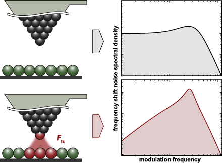
- increased due to a coupling of the phase-locked loop with the amplitude and the distance control loops. While noise in the amplitude control loop itself is essentially independent of the frequency shift noise without tip–sample interaction, amplitude and topography feedback loop noise are coupled into the
- ), the parameter βts can be obtained by using either the frequency shift set-point Δfset for the topography feedback or by the average frequency shift measured at the tip–sample distance zp with deactivated topography feedback loop. For the numerical evaluation of signal vs time traces and noise spectra
- and a significant slow-down of the step-response as shown in Figure 12 of appendix C. A small response time of the topography feedback loop causes a reduced noise in . Conclusions and System Optimisation We realise that the control and data acquisition system of a NC-AFM is a complex network of


![[Graphic 32]](/bjnano/content/inline/2190-4286-7-181-i73.png?max-width=637&scale=1.18182) wit...
wit...

![[Graphic 34]](/bjnano/content/inline/2190-4286-7-181-i75.png?max-width=637&scale=1.18182) wit...
wit...


Generalized Hertz model for bimodal nanomechanical mapping
Beilstein J. Nanotechnol. 2016, 7, 970–982, doi:10.3762/bjnano.7.89

- as amplitude-modulation (AM) AFM [18][19][20]), is one of the most commonly used parametric techniques, where the cantilever is driven on resonance and the cantilever–sample distance is adjusted by a feedback loop to maintain a constant oscillation amplitude at every image pixel. The time required


![[Graphic 4]](/bjnano/content/inline/2190-4286-7-89-i40.png?max-width=637&scale=1.18182) approximation applied to Equation 6 i...
approximation applied to Equation 6 i...


Large area scanning probe microscope in ultra-high vacuum demonstrated for electrostatic force measurements on high-voltage devices
Beilstein J. Nanotechnol. 2015, 6, 2485–2497, doi:10.3762/bjnano.6.258

- certain surface area. The tip height is controlled by a feedback loop correlating the tip–sample interaction with the deflection of the cantilever. However, the interaction force contains many different components which can only be partly suppressed (e.g., magnetic forces when inspecting non-magnetic


Sub-monolayer film growth of a volatile lanthanide complex on metallic surfaces
Beilstein J. Nanotechnol. 2015, 6, 2412–2416, doi:10.3762/bjnano.6.248

- temperature was kept at ≈5 K. The dI/dV spectra were taken using a standard lock-in amplifier technique with a 487 Hz modulation frequency and 20 mV modulation voltage with an open feedback loop. The dI/dV maps were recorded with the same lock-in parameters but with a closed feedback loop. A ball–stick model


Kelvin probe force microscopy for local characterisation of active nanoelectronic devices
Beilstein J. Nanotechnol. 2015, 6, 2193–2206, doi:10.3762/bjnano.6.225

- established technique that allows for the mapping of local electrostatic potentials with an atomic force microscope (AFM) [1][2][3]. In contrast to electrostatic force microscopy (EFM), which measures merely the effect of electrostatic forces on the oscillation of the tip, a feedback loop nullifies the
- on the number of layers. KFM has found widespread use in both vacuum and ambient environments. Most commercial instruments for operation in air include a scan mode based on amplitude modulation KFM (AM-KFM). In this mode, the feedback loop nullifies the cantilever oscillation that is excited by a
- shift Δf, exhibits a frequency component at the electrostatic modulation frequency, which is nullified by the Kelvin feedback loop. Frequency modulated KFM (FM-KFM) [16][17] thus provides a map of potentials required to minimise the electrostatic force gradient, proportional to Δf for small mechanical


![[Graphic 33]](/bjnano/content/inline/2190-4286-6-225-i48.png?max-width=637&scale=1.18182) for different modulation amplitu...
for different modulation amplitu...


Virtual reality visual feedback for hand-controlled scanning probe microscopy manipulation of single molecules
Beilstein J. Nanotechnol. 2015, 6, 2148–2153, doi:10.3762/bjnano.6.220

- tip was stabilized, the STM current feedback loop was opened and the control over the tip position was passed to the operator. The operator contacted the molecule by moving the tip in a strictly vertical trajectory (x,y tip coordinates frozen) until a sharp jump of the I and Δf bar indicators in the


Controlled switching of single-molecule junctions by mechanical motion of a phenyl ring
Beilstein J. Nanotechnol. 2015, 6, 2088–2095, doi:10.3762/bjnano.6.213

- surface normal. The tip was first positioned over the protrusion of the top molecule in (a) at a height corresponding to VS = 50 mV and I = 1 nA, and the feedback loop was turned off. Then the tip was laterally displaced in the [001] direction by 2 Å (indicated by the cross) and moved toward the molecule


Lower nanometer-scale size limit for the deformation of a metallic glass by shear transformations revealed by quantitative AFM indentation
Beilstein J. Nanotechnol. 2015, 6, 1721–1732, doi:10.3762/bjnano.6.176

- . In order to measure topography both amplitude and frequency shift are tracked by a feedback loop so as to keep the cantilever oscillation in resonance [15]. For indentation and imaging we used a diamond-coated silicon single crystalline cantilever (Type: CDT-NCLR, manufactured by NanoSensors). The


Enhanced fullerene–Au(111) coupling in (2√3 × 2√3)R30° superstructures with intermolecular interactions
Beilstein J. Nanotechnol. 2015, 6, 1421–1431, doi:10.3762/bjnano.6.147

- of the ac tunnelling current achieved by modulating the sample bias after switching off the feedback loop. The single crystal Au(111) substrate (MaTecK, Germany) was cleaned in UHV by cycles of Ne+ ion sputtering (1 kV, 10 min) and thermal annealing (600 °C, 20 min). The cleanliness was checked by


Nano-contact microscopy of supracrystals
Beilstein J. Nanotechnol. 2015, 6, 1229–1236, doi:10.3762/bjnano.6.126

- feedback is broadly comparable to that in dSTM, with the particles having the same approximate size and shape with little internal contrast. After completing the DFM scan, the tip was positioned over the centre of a nanocrystal and the feedback loop turned off. The same region was then imaged in constant
- voltage applied (4 V) on the setpoint “stabilisation” current (Is) used to acquire each of the spectra observed in Figure 3C. The stabilisation current is the setpoint value at which the feedback loop operates before the loop is disabled to allow the I(V) measurement to take place. Is therefore provides a

![[Graphic 1]](/bjnano/content/inline/2190-4286-6-126-i1.png?max-width=637&scale=1.18182) = 20 pA, ...
= 20 pA, ...


Closed-loop conductance scanning tunneling spectroscopy: demonstrating the equivalence to the open-loop alternative
Beilstein J. Nanotechnol. 2015, 6, 1116–1124, doi:10.3762/bjnano.6.113

- results and theoretical calculations, these effects only take place at tip–sample separations below 500 pm, i.e., in the z(V) regime of Figure 6. As such, any relaxation effects will be negated by the active feedback loop during z(V) measurements. If this were not the case, the onset of relaxation effects


Optimization of phase contrast in bimodal amplitude modulation AFM
Beilstein J. Nanotechnol. 2015, 6, 1072–1081, doi:10.3762/bjnano.6.108

- feedback loop keeps constant the amplitude of the first mode while the observables of the second mode have not feedback restrictions (bimodal AM). Here we study the conditions to enhance the compositional contrast in bimodal AM while imaging heterogeneous materials. The contrast has a maximum by decreasing
- that involve the attractive regime. The attractive forces have been modeled by van der Waals interactions with the Hamaker values given in Table 1. Phase contrast in the attractive regime (conservative force): A01 > A02 In bimodal AM the feedback loop operates on A1, consequently the amplitude of the


Electroburning of few-layer graphene flakes, epitaxial graphene, and turbostratic graphene discs in air and under vacuum
Beilstein J. Nanotechnol. 2015, 6, 711–719, doi:10.3762/bjnano.6.72

- feedback loop in order to stop the current immediately after the opening of the junction. We used the same method previously employed for the electromigration of gold nanowires [26]. A typical example of the process is visible in Figure 1a. Above a certain voltage value, the I–V curves become strongly non


A scanning probe microscope for magnetoresistive cantilevers utilizing a nested scanner design for large-area scans
Beilstein J. Nanotechnol. 2015, 6, 451–461, doi:10.3762/bjnano.6.46

- × 1024 pixels. Imaging was done in the intermittent contact mode of the AFM with a setpoint of 89% of the free amplitude of the cantilever. Due to the large step heights of up to 2 μm on the surface of the chip, and the corresponding high demands on the z-feedback loop the scan speed was set to 30 μm/s
- tracked with a phase-locked-loop (PLL) while its frequency shift was used as a feedback for the topography feedback loop [6]. As the frequency tracking loop feeds back the cantilevers resonance frequency to the driving signal at a 90°phase shift, the contrast in the phase signal disappears as shown Figure


Boosting the local anodic oxidation of silicon through carbon nanofiber atomic force microscopy probes
Beilstein J. Nanotechnol. 2015, 6, 215–222, doi:10.3762/bjnano.6.20

- present paper. As far as the tips did not make contact with the surface (either by particle contamination or the surface or problems with feedback loop control) we did not observe tip wear. Discussion In Figure 6 the main results of the kinetics study of LAO-AFM are summarized. Figure 6a shows the line


Kelvin probe force microscopy in liquid using electrochemical force microscopy
Beilstein J. Nanotechnol. 2015, 6, 201–214, doi:10.3762/bjnano.6.19

- previously reported [40][41][42][43]. In general, open loop-KPFM does not require the application of a DC bias via a feedback loop and can be performed by utilizing either (i) both AC voltage and DC bias (referred to here as open loop bias spectroscopy, OLBS) [44], or (ii) AC voltage alone (referred to here
- second harmonic cantilever amplitude (Aω and A2ω) and phase (θω and θ2ω) using lock-in techniques. Equation 2 predicts a linear dependence of Fω with respect to the probe–sample DC bias, which is minimized when Vdc = Vcpd. KPFM employs this principle via a feedback loop to minimize Aω. Depending on the
- result in similar, if not more catastrophic, bubble formation by virtue of the absence of a defined minimum, which may result in the application of large DC biases by the feedback loop. Figure 1 demonstrates that the universal application of KPFM across all materials, all bias ranges and all solutions is


![[Graphic 6]](/bjnano/content/inline/2190-4286-6-19-i11.png?max-width=637&scale=1.18182) response collected 200 nm above a grounded Au electrode in (a, b, c) air, (d, e, f) decane an...
response collected 200 nm above a grounded Au electrode in (a, b, c) air, (d, e, f) decane an...


![[Graphic 22]](/bjnano/content/inline/2190-4286-6-19-i27.png?max-width=637&scale=1.18182) spectra [bias-on] collected 500 nm above HOPG in aqueous solutions of increasing salt concent...
spectra [bias-on] collected 500 nm above HOPG in aqueous solutions of increasing salt concent...

![[Graphic 25]](/bjnano/content/inline/2190-4286-6-19-i30.png?max-width=637&scale=1.18182) spectra [bias-on] collected 500 nm above (a) HOPG and (b) Au in milli-Q water (vertical color...
spectra [bias-on] collected 500 nm above (a) HOPG and (b) Au in milli-Q water (vertical color...

![[Graphic 27]](/bjnano/content/inline/2190-4286-6-19-i32.png?max-width=637&scale=1.18182) spectra [bias-on] recorded 500 nm above a HOPG/Au boundary in milli-Q water. T...
spectra [bias-on] recorded 500 nm above a HOPG/Au boundary in milli-Q water. T...

Accurate, explicit formulae for higher harmonic force spectroscopy by frequency modulation-AFM
Beilstein J. Nanotechnol. 2015, 6, 149–156, doi:10.3762/bjnano.6.14

- formulae for both conservative and dissipative forces. In FM-AFM, a cantilever is oscillated at its resonance frequency using an external driving force and a feedback loop. The motion of the cantilever is often modelled as a driven damped harmonic oscillator with an additional force, Fts, stemming from tip


High-frequency multimodal atomic force microscopy
Beilstein J. Nanotechnol. 2014, 5, 2459–2467, doi:10.3762/bjnano.5.255

- scanner feedback loop is then closed by enforcing a higher drive amplitude than the free drive amplitude. As the tip–sample distance decreases, the force interaction becomes stronger and energy is lost from the cantilever oscillation. By using this technique, the non-monotonic tip–surface interaction


Patterning a hydrogen-bonded molecular monolayer with a hand-controlled scanning probe microscope
Beilstein J. Nanotechnol. 2014, 5, 1926–1932, doi:10.3762/bjnano.5.203

- contacting and the current feedback loop of the SPM software was opened. The contact to the molecule was established by approaching the tip vertically towards the surface; this approach was effected by downward movement of the hand of the operator. Over the course of HCM the current I flowing through the
- the tip with the removed PTCDA molecule hanging on its apex towards the Ag(111) surface and applying a voltage pulse of 0.6–1 V. Afterwards the current feedback loop was closed and the manipulation area was scanned in constant current STM mode (a movie that was made of the scanned STM images can be
- )-coordinates of the marker are extracted. These coordinates are converted into a set of three voltages vx, vy, vz that are further added to the ux, uy, uz voltages of the SPM software used to control the scanning piezo-elements of the microscope. In this way when the feedback loop is closed the position of the


Probing the electronic transport on the reconstructed Au/Ge(001) surface
Beilstein J. Nanotechnol. 2014, 5, 1463–1471, doi:10.3762/bjnano.5.159

- current Itrans through the surface while the third tip measures the STM topography and the potential, simultaneously. Therefore, a feedback loop adjusts the dc tunnelling voltage such that the dc tunnelling current becomes zero. Thus, for each lateral tip position the applied dc tunnelling voltage


Control theory for scanning probe microscopy revisited
Beilstein J. Nanotechnol. 2014, 5, 337–345, doi:10.3762/bjnano.5.38

- [13]. However, the details of the operation of the feedback loop have been incorrectly modelled, which results in a decreased stability and an exaggerated ringing at the resonant frequency of the piezoelectric actuator (z-piezo). Due to these errors, the feedback controller often cannot maintain
- tracking without a high derivative component [13], which is entirely at odds with experimental observations. This paper employs analysis of specific SPM PI controllers to provide a more appropriate method for modelling such systems. Results and Discussion When modelling an SPM feedback loop we must first
- SPM system we will first derive the model for the full SPM feedback system, and then set the transfer functions of unmodelled components to unity, to reduce the possibility for errors following their introduction. To avoid unnecessary generalisations we will discuss the feedback loop as it applies to


Manipulation of nanoparticles of different shapes inside a scanning electron microscope
Beilstein J. Nanotechnol. 2014, 5, 133–140, doi:10.3762/bjnano.5.13

- ). During the manipulation, the tip moved parallel to the surface along a straight line without feedback loop. At the end of every manipulation event the tip was abruptly retracted from the NP to avoid sticking of the particle to the tip. Two different modes of the tip oscillation direction were used in


