Search results
Search for "composites" in Full Text gives 41 result(s) in Beilstein Journal of Organic Chemistry.
Advantages of PROTACs in achieving selective degradation of homologous protein families
- Luxi Yang,
- Xinfei Mao,
- Jingyi Zhang,
- Jing Shu,
- Wenhai Huang,
- Xiaowu Dong,
- Yinqiao Chen and
- Mingfei Wu
Beilstein J. Org. Chem. 2026, 22, 628–661, doi:10.3762/bjoc.22.49


Graphical Abstract

Figure 1: Mechanism of a PROTAC-mediated targeted protein degradation. Created in BioRender. Wu, M. (2026) ht...

Figure 2: CDK4/6 PROTACs with alkyl or PEG chains as linkers.

Figure 3: CDK4/6 PROTACs with triazole-containing linkers.

Figure 4: Structures of AT-7519 (7) and FN-1501 (8), and CDK9 degrading PROTACs based on compound 8 with vari...

Figure 5: CDK9 PROTACs with alkane chain as linkers or triazole linkers.

Figure 6: Structures of HDAC6 inhibitors ACY1215 (17) and ACY-241 (18), as well as the structure of PROTACs 1...

Figure 7: C4-linked-series and C5-linked-series of HDAC6 PROTACs.

Figure 8: Structures of VHL-based degraders.

Figure 9: Structures of VHL-based and CRBN-based selective HDAC PROTACs.

Figure 10: Structures of the “amide series” and “phenyl series” PROTACs studied by Crews et al.

Figure 11: Structures of the “amide series” PROTACs.

Figure 12: Structures of the “phenyl series” PROTACs.

Figure 13: Structures of JQ1 (34) and MZ1 (35).

Figure 14: Structures of macro-PROTAC-1 and SHD913.

Figure 15: Commonly utilized thalidomide-derived CRBN ligands and possible linker attachment styles. A1, A2: p...

Figure 16: VHL ligands frequently used in PROTACs. Linker attachment options are represented with curly bonds ...

Figure 17: Varying the inhibitor warhead and the recruited E3 ligase permits targets to be accessed for degrad...

Figure 18: Structures of YX-2-233 (42) and YX-2-107 (43).

Figure 19: Structures of compounds 44 and 45.

Figure 20: Design of the SGK3 PROTACs.

Figure 21: CRBN, VHL, and IAP ligands used when designing HDAC-PROTACs.

Figure 22: CDK4/6-PROTACs with different E3 ligands targeting the same E3 ubiquitin ligase.

Figure 23: Structural basis for the selective degradation of CDK6 over CDK4 by PROTAC 2. (A) CDK4–molecule 2–C...

Figure 24: Regarding the PPI-driven selectivity mechanism of two PROTAC molecules, SJF-α and SJF-δ, for p38α a...

Figure 25: Co-crystal structure and ultra-high selectivity of the STAT6 PROTAC degrader AK-1690. (A) STAT6–AK-...
C2 to C6 biobased carbonyl platforms for fine chemistry
- Jingjing Jiang,
- Muhammad Noman Haider Tariq,
- Florence Popowycz,
- Yanlong Gu and
- Yves Queneau
Beilstein J. Org. Chem. 2025, 21, 2103–2172, doi:10.3762/bjoc.21.165


Graphical Abstract

Figure 1: C2–C6 biobased carbonyl building blocks.

Scheme 1: Proposed (2 + 2) route to glycolaldehyde and glycolic acid from erythritol by Cu/AC catalyst (AC = ...

Scheme 2: Reductive amination of GCA.

Scheme 3: N-Formylation of secondary amines by reaction with GCA.

Scheme 4: Synthesis and conversion of hydroxy acetals to cyclic acetals.

Scheme 5: Synthesis of 3-(indol-3-yl)-2,3-dihydrofurans via three-component reaction of glycolaldehyde, indol...

Scheme 6: BiCl3-catalyzed synthesis of benzo[a]carbazoles from 2-arylindoles and α-bromoacetaldehyde ethylene...

Scheme 7: Cu/NCNSs-based conversion of glycerol to glycolic acid and other short biobased acids.

Scheme 8: E. coli-based biotransformation of C1 source molecules (CH4, CO2 and CO) towards C2 glycolic acid.

Scheme 9: N-Formylation of amines with C2 (a) or C3 (b) biomass-based feedstocks.

Scheme 10: Methods for the formation of propanoic acid (PA) from lactic acid (LA).

Scheme 11: Co-polymerization of biobased lactic acid and glycolic acid via a bicatalytic process.

Scheme 12: Oxidation of α-hydroxy acids by tetrachloroaurate(III) in acetic acid–sodium acetate buffer medium.

Figure 2: Selective catalytic pathways for the conversion of lactic acid (LA).

Scheme 13: Synthesis of 1,3-PDO via cross-aldol reaction between formaldehyde and acetaldehyde to 3-hydroxypro...

Scheme 14: Hydrothermal conversion of 1,3-dihydroxy-2-propane and 2,3-dihydroxypropanal to methylglyoxal.

Scheme 15: FLS-catalyzed formose reaction to synthesize GA and DHA.

Scheme 16: GCA and DHA oxidation products of glycerol and isomerization of GCA to DHA under flow conditions us...

Scheme 17: Acid-catalyzed reactions of DHA with alcohols.

Scheme 18: Synthesis of dihydroxyacetone phosphate from dihydroxyacetone.

Scheme 19: Bifunctional acid–base catalyst DHA conversion into lactic acid via pyruvaldehyde or fructose forma...

Scheme 20: Catalytic one-pot synthesis of GA and co-synthesis of formamides and formates from DHA.

Scheme 21: (a) Synthesis of furan derivatives and (b) synthesis of thiophene derivative by cascade [3 + 2] ann...

Scheme 22: Brønsted acidic ionic liquid catalyzed synthesis of benzo[a]carbazole from renewable acetol and 2-p...

Scheme 23: Asymmetric hydrogenation of α-hydroxy ketones to 1,2-diols.

Scheme 24: Synthesis of novel 6-(substituted benzylidene)-2-methylthiazolo [2,3-b]oxazol-5(6H)-one from 1-hydr...

Scheme 25: ʟ-Proline-catalyzed synthesis of anti-diols from hydroxyacetone and aldehydes.

Scheme 26: C–C-bond-formation reactions of a biomass-based feedstock aromatic aldehyde (C5) and hydroxyacetone...

Scheme 27: Ethanol upgrading to C4 bulk chemicals via the thiamine (VB1)-catalyzed acetoin condensation.

Scheme 28: One-pot sequential chemoenzymatic synthesis of 2-aminobutane-1,4-diol and 1,2,4-butanetriol via 1,4...

Scheme 29: Synthesis of 1,4-dihydroxybutan-2-one by microbial transformation.

Scheme 30: Conversion of polyols by [neocuproine)Pd(OAc)]2(OTf)2] to α-hydroxy ketones.

Scheme 31: Chemoselective oxidation of alcohols with chiral palladium-based catalyst 2.

Scheme 32: Electrochemical transformation of furfural to 5-hydroxy-2(5H)-furanone (HFO).

Scheme 33: Selective hydrodeoxygenation of HFO and oxidation to γ-butyrolactone (GBL).

Scheme 34: Photosensitized oxygenation of furan towards HFO via ozonide intermediates.

Scheme 35: Conversion of furfural to HFO and MAN by using mesoporous carbon nitride (SGCN) as photocatalyst.

Scheme 36: Synthesis of HFO from furan derivatives.

Scheme 37: Photooxidation of furfural to 5-hydroxy-2(5H)-furanone (HFO).

Scheme 38: Synthesis of Friedel–Crafts indole adduct from HFO.

Scheme 39: Conversion of HFO to α,γ-substituted chiral γ-lactones.

Scheme 40: Tautomeric transformation of HFO to formylacrylic acid.

Scheme 41: Hydrolysis of HFO to succinic acid in aqueous solution.

Scheme 42: Substitution and condensation reactions of 5-hydroxy-2(5H)-furanone (HFO).

Scheme 43: (a) Conversion of HFO towards valuable C4 chemicals and (b) anodic oxidation of 5-hydroxy-2(5H)-fur...

Figure 3: Conversion of HFO towards other natural and synthetic substances.

Scheme 44: Conversion of furfural to maleic anhydride (reaction a: VOx/Al2O3; reaction b: VPO).

Scheme 45: Conversion of furfural into succinic acid.

Scheme 46: Electro‑, photo‑, and biocatalysis for one-pot selective conversions of furfural into C4 chemicals.

Scheme 47: Production route of furfural from hemicellulose.

Scheme 48: Mechanism for xylose dehydration to furfural through a choline xyloside intermediate.

Scheme 49: Conversion of furfural to furfuryl alcohol and its derivatives.

Scheme 50: Conversion of furfural to furfuryl alcohol and 3-(2-furyl)acrolein.

Scheme 51: The aerobic oxidative condensation of biomass-derived furfural and linear alcohols.

Scheme 52: The single-step synthesis of 2-pentanone from furfural.

Scheme 53: Electrocatalytic coupling reaction of furfural and levulinic acid.

Scheme 54: Conversion of furfural to m-xylylenediamine.

Scheme 55: Conversion of furfural to tetrahydrofuran-derived amines.

Scheme 56: Formation of trans-4,5-diamino-cyclopent-2-enones from furfural.

Scheme 57: Production of pyrrole and proline from furfural.

Scheme 58: Synthesis of 1‑(trifluoromethyl)-8-oxabicyclo[3.2.1]oct-3-en-2-ones from furfural.

Scheme 59: Conversion of furfural to furfural-derived diacids.

Scheme 60: A telescope protocol derived from furfural and glycerol.

Scheme 61: A tandem cyclization of furfural and 5,5-dimethyl-1,3-cyclohexanedione.

Scheme 62: A Ugi four-component reaction to construct furfural-based polyamides.

Scheme 63: One-pot synthesis of γ-acyloxy-Cy7 from furfural.

Scheme 64: Dimerization–Piancatelli sequence toward humins precursors from furfural.

Scheme 65: Conversion of furfural to CPN.

Scheme 66: Synthesis of jet fuels range cycloalkanes from CPN and lignin-derived vanillin.

Scheme 67: Solar-energy-driven synthesis of high-density biofuels from CPN.

Scheme 68: Reductive amination of CPN to cyclopentylamine.

Scheme 69: Asymmetric hydrogenation of C=O bonds of exocyclic α,β-unsaturated cyclopentanones.

Scheme 70: Preparation of levulinic acid via the C5 route (route a) or C6 route (routes b1 and b2).

Scheme 71: Mechanism of the rehydration of HMF to levulinic acid and formic acid.

Scheme 72: Important levulinic acid-derived chemicals.

Scheme 73: Direct conversion of levulinic acid to pentanoic acid.

Scheme 74: Catalytic aerobic oxidation of levulinic acid to citramalic acid.

Scheme 75: Conversion of levulinic acid to 1,4-pentanediol (a) see ref. [236]; b) see ref. [237]; c) see ref. [238]; d) see r...

Scheme 76: Selective production of 2-butanol through hydrogenolysis of levulinic acid.

Scheme 77: General reaction pathways proposed for the formation of 5MPs from levulinic acid.

Scheme 78: Selective reductive amination of levulinic acid to N-substituted pyrroles.

Scheme 79: Reductive amination of levulinic acid to chiral pyrrolidinone.

Scheme 80: Reductive amination of levulinic acid to non-natural chiral γ-amino acid.

Scheme 81: Nitrogen-containing chemicals derived from levulinic acid.

Scheme 82: Preparation of GVL from levulinic acid by dehydration and hydrogenation.

Scheme 83: Ruthenium-catalyzed levulinic acid to chiral γ-valerolactone.

Scheme 84: Catalytic asymmetric hydrogenation of levulinic acid to chiral GVL.

Scheme 85: Three steps synthesis of ε-caprolactam from GVL.

Scheme 86: Multistep synthesis of nylon 6,6 from GVL.

Scheme 87: Preparation of MeGVL by α-alkylation of GVL.

Scheme 88: Ring-opening polymerization of five-membered lactones.

Scheme 89: Synthesis of GVL-based ionic liquids.

Scheme 90: Preparation of butene isomers from GVL under Lewis acid conditions.

Scheme 91: Construction of C5–C12 fuels from GVL over nano-HZSM-5 catalysts.

Scheme 92: Preparation of alkyl valerate from GVL via ring opening/reduction/esterification sequence.

Scheme 93: Construction of 4-acyloxypentanoic acids from GVL.

Scheme 94: Synthesis of 1,4-pentanediol (PDO) from GVL.

Scheme 95: Construction of novel cyclic hemiketal platforms via self-Claisen condensation of GVL.

Scheme 96: Copper-catalyzed lactamization of GVL.

Figure 4: Main scaffolds obtained from HMF.

Scheme 97: Biginelli reactions towards HMF-containing dihydropyrimidinones.

Scheme 98: Hantzsch dihydropyridine synthesis involving HMF.

Scheme 99: The Kabachnik–Fields reaction involving HMF.

Scheme 100: Construction of oxazolidinone from HMF.

Scheme 101: Construction of rhodamine-furan hybrids from HMF.

Scheme 102: A Groebke–Blackburn–Bienaymé reaction involving HMF.

Scheme 103: HMF-containing benzodiazepines by [4 + 2 + 1] cycloadditions.

Scheme 104: Synthesis of fluorinated analogues of α-aryl ketones.

Scheme 105: Synthesis of HMF derived disubstituted γ-butyrolactone.

Scheme 106: Functionalized aromatics from furfural and HMF.

Scheme 107: Diels–Alder adducts from HMF or furfural with N-methylmaleimide.

Scheme 108: Pathway of the one-pot conversion of HMF into phthalic anhydride.

Scheme 109: Photocatalyzed preparation of humins (L-H) from HMF mixed with spoiled HMF residues (LMW-H) and fur...

Scheme 110: Asymmetric dipolar cycloadditions on HMF.

Scheme 111: Dipolar cycloadditions of HMF based nitrones to 3,4- and 3,5-substituted isoxazolidines.

Scheme 112: Production of δ-lactone-fused cyclopenten-2-ones from HMF.

Scheme 113: Aza-Piancatelli access to aza-spirocycles from HMF-derived intermediates.

Scheme 114: Cross-condensation of furfural, acetone and HMF into C13, C14 and C15 products.

Scheme 115: Base-catalyzed aldol condensation/dehydration sequences from HMF.

Scheme 116: Condensation of HMF and active methylene nitrile.

Scheme 117: MBH reactions involving HMF.

Scheme 118: Synthesis of HMF-derived ionic liquids.

Scheme 119: Reductive amination/enzymatic acylation sequence towards HMF-based surfactants.

Scheme 120: The formation of 5-chloromethylfurfural (CMF).

Scheme 121: Conversion of CMF to HMF, levulinic acid, and alkyl levulinates.

Scheme 122: Conversion of CMF to CMFCC and FDCC.

Scheme 123: Conversion of CMF to BHMF.

Scheme 124: Conversion of CMF to DMF.

Scheme 125: CMF chlorine atom substitutions toward HMF ethers and esters.

Scheme 126: Introduction of carbon nucleophiles in CMF.

Scheme 127: NHC-catalyzed remote enantioselective Mannich-type reactions of CMF.

Scheme 128: Conversion of CMF to promising biomass-derived dyes.

Scheme 129: Radical transformation of CMF with styrenes.

Scheme 130: Synthesis of natural herbicide δ-aminolevulinic acid from CMF.

Scheme 131: Four step synthesis of the drug ranitidine from CMF.

Scheme 132: Pd/CO2 cooperative catalysis for the production of HHD and HXD.

Scheme 133: Different ruthenium (Ru) catalysts for the ring-opening of 5-HMF to HHD.

Scheme 134: Proposed pathways for preparing HXD from HMF.

Scheme 135: MCP formation and uses.

Scheme 136: Cu(I)-catalyzed highly selective oxidation of HHD to 2,5-dioxohexanal.

Scheme 137: Synthesis of N‑substituted 3‑hydroxypyridinium salts from 2,5-dioxohexanal.

Scheme 138: Ru catalyzed hydrogenations of HHD to 1,2,5-hexanetriol (a) see ref. [396]; b) see ref. [397]).

Scheme 139: Aviation fuel range quadricyclanes produced by HXD.

Scheme 140: Synthesis of HDGK from HXD and glycerol as a chain extender.

Scheme 141: Synthesis of serinol pyrrole from HXD and serinol.

Scheme 142: Synthesis of pyrroles from HXD and nitroarenes.

Scheme 143: Two-step production of PX from cellulose via HXD.

Scheme 144: Preparation of HCPN from HMF via hydrogenation and ring rearrangement.

Scheme 145: Suggested pathways from HMF to HCPN.

Scheme 146: α-Alkylation of HCPN with ethylene gas.

Scheme 147: Synthesis of 3-(hydroxymethyl)cyclopentylamine from HMF via reductive amination of HCPN.

Scheme 148: Production of LGO and Cyrene® from biomass.

Scheme 149: Synthesis of HBO from LGO and other applications.

Scheme 150: Construction of m-Cyrene® homopolymer.

Scheme 151: Conversion of Cyrene® to THFDM and 1,6-hexanediol.

Scheme 152: RAFT co-polymerization of LGO and butadienes.

Scheme 153: Polycondensation of HO-LGOL and diols with dimethyl adipate.

Scheme 154: Self-condensation of Cyrene® and Claisen–Schmidt reactions.

Scheme 155: Synthesis of 5-amino-2-(hydroxymethyl)tetrahydropyran from Cyrene®.
Applications of microscopy and small angle scattering techniques for the characterisation of supramolecular gels
- Connor R. M. MacDonald and
- Emily R. Draper
Beilstein J. Org. Chem. 2024, 20, 2608–2634, doi:10.3762/bjoc.20.220


Graphical Abstract

Figure 1: Hierarchical assembly occurring across length scales. Molecular interactions result in fibres which...

Figure 2: Three-dimensional CLSM image of a multicomponent supramolecular structure. The three-dimensional CL...

Figure 3: AFM images of air-dried aqueous Fmoc-FF, Fmoc-S, and 1:1 Fmoc-FF:Fmoc-S solutions. Figure 3 was reprinted f...

Figure 4: (a) 3D CLSM images of macroscopically a self-sorting gel network, where all fibres were stained gre...

Figure 5: (a) 3D AFM topographic image of dried elastin fibre. (b) Indicative height and diameter profile plo...

Figure 6: The nano-to-micro imaging range of SEM and TEM [30]. Cartoons represent the nanoparticles, pores, nanow...

Figure 7: Cartoon of artifacts caused by blotting and thinning. a) Alignment of threadlike micelles (left) [32] a...

Figure 8: (a) Chemical structures of monomer compounds and a schematic of the resulting chiral helical struct...

Figure 9: Commonly observed entanglements of urea-based supramolecular helices. (a) Double helix, (b) quadrup...

Figure 10: (a) SEM image of a single three-stranded braid showing a defect in which the braid separates into s...

Figure 11: Visualization of individual atoms at 1.25 Å resolution. Three apoferritin residues are shown at hig...

Figure 12: Cartoon of a general small-angle scattering setup.

Figure 13: (a) SAXS data and fits for solution in H2O (open symbols) and D2O (closed symbols). Cryo-TEM data f...

Figure 14: (a) A cartoon illustrating the orientation phases caused by shear alignment of WLMs. (b) Rheologica...

Figure 15: (a) Chemical structure of 2NapFF and (b) a cartoon cross-section of the hollow cylinder structure f...

Figure 16: Length scales of scattering and imaging techniques [16,54,55].

Figure 17: A schematic of a hydrogel network showing the significance of various parameters extracted from SAN...

Figure 18: The morphologies of a co-assembled complex dependent on the solvent composition. Figure 18 is from [89] and was ...

Figure 19: Allowed and forbidden crossings of entangled helices. Figure 19 is from [44] and was adapted by permission from ...

Figure 20: (a) Cryo-TEM density map of self-assembled (ʟ,ʟ)-2NapFF. (b) Computational model fit to cryo-TEM ma...

Figure 21: Map showing an incomplete list of global scientific centres providing access to (a) cryo-EM in red ...

Figure 22: SANS at a range of times. Solid lines are fits to a hollow cylinder model (T = 114 min and T = 202 ...

Figure 23: SAXS data of 5 mg/mL alanine-functionalised perylene bisimide (PBI-A) in 20 v/v % MeOH at pH (a) 2;...

Figure 24: Cryo-TEM sample prepared using plunge freezing in liquid nitrogen slush and sublimed for 30 minutes...
Green and sustainable approaches for the Friedel–Crafts reaction between aldehydes and indoles
- Periklis X. Kolagkis,
- Eirini M. Galathri and
- Christoforos G. Kokotos
Beilstein J. Org. Chem. 2024, 20, 379–426, doi:10.3762/bjoc.20.36

- . immobilized carbon nanotubes on sulfonated polyacrylamide creating polymer/carbon nanotube composites, which could also be employed in the synthesis of BIMs [115][116]. This methodology used a catalyst loading of 5 mol % under reflux conditions (85 °C) in acetonitrile for 30–40 minutes with product yields

Graphical Abstract

Scheme 1: Examples of BIMs used for their medicinal properties.

Scheme 2: Mechanisms for the synthesis of BIMs using protic or Lewis acids as catalysts.

Scheme 3: Synthesis of bis(indolyl)methanes using DBDMH.

Scheme 4: Competition experiments and synthesis of bis(indolyl)methanes using DBDMH.

Scheme 5: Proposed mechanism for formation of BIM of using DBDMH.

Scheme 6: Synthesis of bis(indolyl)methanes using I2.

Scheme 7: General reaction mechanism upon halogen bonding.

Scheme 8: Synthesis of bis(indolyl)methanes using I2, introduced by Ji.

Scheme 9: Synthesis of bis(indolyl)methanes using Br2 in CH3CN.

Scheme 10: Βidentate halogen-bond donors.

Scheme 11: Synthesis of bis(indolyl)methanes using bidentate halogen-bond donor 26.

Scheme 12: Proposed reaction mechanism.

Scheme 13: Synthesis of bis(indolyl)methanes using iodoalkyne as catalyst.

Scheme 14: Proposed reaction mechanism.

Scheme 15: Optimized reaction conditions used by Ramshini.

Scheme 16: Activation of the carbonyl group by HPA/TPI-Fe3O4.

Scheme 17: Synthesis of BIMs in the presence of nanoAg-Pt/SiO2-doped silicate.

Scheme 18: Mechanism of action proposed by Khalafi-Nezhad et al.

Scheme 19: Activation of the carbonyl group by the Cu–isatin Schiff base complex.

Scheme 20: Optimum reaction conditions published by Jain.

Scheme 21: Organocatalytic protocol utilizing nanoparticles introduced by Bankar.

Scheme 22: Activation of the carbonyl group by the AlCl3·6H2O-SDS-SiO2 complex.

Scheme 23: Optimal reaction conditions for the aforementioned nano-Fe3O4 based catalysts.

Scheme 24: Nanocatalytic protocol proposed by Kaur et al.

Scheme 25: Microwave approach introduced by Yuan.

Scheme 26: Microwave approach introduced by Zahran et al.

Scheme 27: Microwave irradiation protocol introduced by Bindu.

Scheme 28: Silica-supported microwave irradiation protocol.

Scheme 29: Proposed mechanism for formation of BIM by Nongkhlaw.

Scheme 30: Microwave-assisted synthesis of BIMs catalyzed by succinic acid.

Scheme 31: Proposed mechanism of action of MMO-4.

Scheme 32: Catalytic approach introduced by Muhammadpoor-Baltork et al.

Scheme 33: Reaction conditions used by Xiao-Ming.

Scheme 34: Ultrasonic irradiation-based protocol published by Saeednia.

Scheme 35: Pyruvic acid-mediated synthesis of BIMs proposed by Thopate.

Scheme 36: Synthesis of BIMs using [bmim]BF4 or [bmim]PF6 ionic liquids.

Scheme 37: Synthesis of BIMs utilizing In(OTf)3 in octylmethylimidazolium hexafluorophosphate as ionic liquid.

Scheme 38: FeCl3·6H2O-catalyzed synthesis of BIMs with use of ionic liquid.

Scheme 39: Synthesis of BIMs utilizing the [hmim]HSO4/EtOH catalytic system.

Scheme 40: Synthesis of BIMs utilizing acidic ionic liquid immobilized on silica gel (ILIS-SO2Cl).

Scheme 41: The [bmim][MeSO4]-catalyzed reaction of indole with various aldehydes.

Scheme 42: The role of [bmim][MeSO4] in catalyzing the reaction of indole with aldehydes.

Scheme 43: Synthesis of BIMs utilizing FeCl3-based ionic liquid ([BTBAC]Cl-FeCl3) as catalyst.

Scheme 44: Synthesis of BIMs using [Msim]Cl at room temperature.

Scheme 45: [Et3NH][H2PO4]-catalyzed synthesis of bis(indolyl)methanes.

Scheme 46: PILs-catalyzed synthesis of bis(indolyl)methanes.

Scheme 47: FSILs-mediated synthesis of bis(indolyl)methanes.

Scheme 48: Possible “release and catch” catalytic process.

Scheme 49: Synthesis of bis(indolyl)methanes by [DABCO-H][HSO4].

Scheme 50: Synthesis of bis(indolyl)methanes by [(THA)(SO4)].

Scheme 51: Synthesis of BBSI-Cl and BBSI-HSO4.

Scheme 52: Synthesis of BIMs in the presence of BBSI-Cl and BBSI-HSO4.

Scheme 53: Chemoselectivity of the present method.

Scheme 54: Synthesis of BIMs catalyzed by chitosan-supported ionic liquid.

Scheme 55: Proposed mechanism of action of CSIL.

Scheme 56: Optimization of the reaction in DESs.

Scheme 57: Synthesis of BIMs using ChCl/SnCl2 as DES.

Scheme 58: Synthesis of BIMs derivatives in presence of DES.

Scheme 59: BIMs synthesis in choline chloride/urea (CC/U).

Scheme 60: Flow chemistry-based synthesis of BIMs by Ley.

Scheme 61: Flow chemistry-based synthesis of BIMs proposed by Nam et al.

Scheme 62: Amino-catalyzed reaction of indole with propionaldehyde.

Scheme 63: Aminocatalytic synthesis of BIMs.

Scheme 64: Proposed mechanism for the aminocatalytic synthesis of BIMs.

Scheme 65: Enzymatic reaction of indole with aldehydes.

Scheme 66: Proposed mechanism for the synthesis of BIMs catalyzed by TLIM.

Scheme 67: Proposed reaction mechanism by Badsara.

Scheme 68: Mechanism proposed by D’Auria.

Scheme 69: Photoinduced thiourea catalysis.

Scheme 70: Proposed mechanism of photoacid activation.

Scheme 71: Proposed mechanism of action for CF3SO2Na.

Scheme 72: Proposed mechanism for the synthesis of BIMs by Mandawad.

Scheme 73: Proposed mechanism for the (a) acid generation and (b) synthesis of BIMs.

Scheme 74: a) Reaction conditions employed by Khaksar and b) activation of the carbonyl group by HFIP.

Scheme 75: Activation of the carbonyl group by the PPy@CH2Br through the formation of a halogen bond.

Scheme 76: Reaction conditions utilized by Mhaldar et al.

Scheme 77: a) Reaction conditions employed by López and b) activation of the carbonyl group by thiourea.

Scheme 78: Infrared irradiation approach introduced by Luna-Mora and his research group.

Scheme 79: Synthesis of BIMs with the use of the Fe–Zn BMOF.
Facile access to pyridinium-based bent aromatic amphiphiles: nonionic surface modification of nanocarbons in water
- Lorenzo Catti,
- Shinji Aoyama and
- Michito Yoshizawa
Beilstein J. Org. Chem. 2024, 20, 32–40, doi:10.3762/bjoc.20.5

- guest-derived absorption bands around 340 nm and 420–650 nm, confirming the solubilization of C60 in water (Figure 4b). Similar host–guest composites were also obtained using PA-CH3, PA-OH, and PA-Im under the same conditions. It is noteworthy that the C60-solubilization efficiency varied depending on
- size of these nanocarbons, the resultant host–guest composites were subjected to UV–visible analysis without further filtration following centrifugation (16,000g, ≈10 min). The obtained UV–visible spectra of the blackish, clear solutions of (PA-OCH3)n·(GN)m, (PA-OCH3)n·(s-CNT)m, and (PA-OCH3)n·(m-CNT)m
- thus enabled the efficient water-solubilization of nanocarbons independent of their size and shape (i.e., spherical, planar, and tubular objects). Electrostatic surface properties of hosts and host–guest composites Zeta potential (ZP) measurements were employed to further study the electrostatic

Graphical Abstract

Figure 1: a) Previous methods for the water-solubilization and modification of nanocarbons (NCs). b) Bent aro...

Figure 2: a) Synthetic route toward prePA and PA-CH3, including the optimized structure (DFT) of PA-CH3. b) S...

Figure 3: 1H NMR spectra (500 MHz, rt, 0.5 mM and 1.0 mM based on PA-CH3 and PA-OCH3, respectively, TMS in CD...

Figure 4: a) General protocol for the noncovalent encircling of C60 and s-CNT by PA-R. b) UV–visible spectra ...

Figure 5: 1H NMR spectra (500 MHz, D2O, rt, 0.5 mM based on PA-Im) of (PA-Im)n·(C60)m a) before and b) after ...

Figure 6: a) Protocol for the noncovalent encircling of g-C3N4 by PA-OCH3 and subsequent deposit of g-C3N4 on...
Enabling artificial photosynthesis systems with molecular recycling: A review of photo- and electrochemical methods for regenerating organic sacrificial electron donors
- Grace A. Lowe
Beilstein J. Org. Chem. 2023, 19, 1198–1215, doi:10.3762/bjoc.19.88
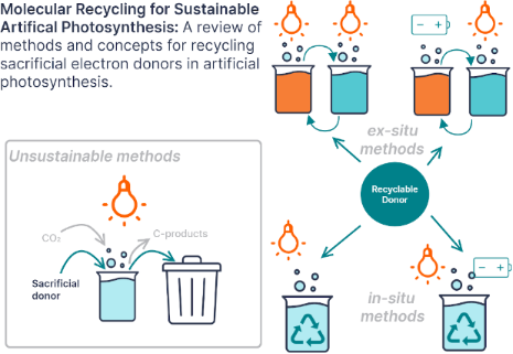
- photocatalyst composites, such as decorated quantum dots [4]. Most of the particulate Z-schemes use inorganic rather than organic redox mediators [2]. Interestingly, soluble redox mediators can be replaced by conducting substrates in inorganic Z-schemes to create ‘redox mediator-free’ schemes [2][4]. For

Graphical Abstract

Figure 1: Diagram comparing the two reaction pathways for sacrificial electron donors (SD) in photocatalyzed ...

Figure 2: Diagram showing water-splitting systems developed by Girault, Scanlon, and co-workers that employ i...

Figure 3: Diagram illustrating the transfer of electrons in a photocatalytic particulate suspensions Z-scheme...

Figure 4: A. Structures of the molecules represented in part B. The numbers in brackets correspond to the com...

Figure 5: A. Structures of the molecules represented in part B. The numbers in brackets correspond to the com...
Cyclodextrins as building blocks for new materials
- Miriana Kfoury and
- Sophie Fourmentin
Beilstein J. Org. Chem. 2023, 19, 889–891, doi:10.3762/bjoc.19.66

- , and so on [14][15][16][17]. In addition to bearing a rigid skeleton, CDs act as versatile multitasking agents. They add value to these composites as their cavities remain generally available to accommodate active substances, or they work as supramolecular catalysts or molecular concealers. Due to the
From amines to (form)amides: a simple and successful mechanochemical approach
- Federico Casti,
- Rita Mocci and
- Andrea Porcheddu
Beilstein J. Org. Chem. 2022, 18, 1210–1216, doi:10.3762/bjoc.18.126

- assistance with the generation of the 1H, 13C NMR, and GC–MS spectroscopic data. Funding This research was funded by MIUR Italy, PRIN 2017 project (grant number: 2017B7MMJ5_001) “MultIFunctional poLymer cOmposites based on groWn matERials (MIFLOWER) and Fondazione di Sardegna (FdS, F72F20000230007).
A trustworthy mechanochemical route to isocyanides
- Francesco Basoccu,
- Federico Cuccu,
- Federico Casti,
- Rita Mocci,
- Claudia Fattuoni and
- Andrea Porcheddu
Beilstein J. Org. Chem. 2022, 18, 732–737, doi:10.3762/bjoc.18.73

- Ricerca d'Ateneo) core facility of the University of Cagliari and Dr. Sandrina Lampis for assistance with the generation of the 1H and 13C NMR spectroscopic data. Funding This research was funded by MIUR Italy, PRIN 2017 project (grant number: 2017B7MMJ5_001) “MultIFunctional poLymer cOmposites based on

Graphical Abstract

Scheme 1: Historic synthetic approaches.

Figure 1: Resonance forms of isocyanides.

Scheme 2: Comparison between the previous mechanochemical synthetic pathway [24] and the new adapted one in this ...

Scheme 3: The scope of our isocyanide synthesis using aliphatic and aromatic primary formamides. Reaction con...

Figure 2: The purification process of a brownish isocyanide on a short silica pad.

Scheme 4: Suggested proton transfer mechanism.
Adjusting the length of supramolecular polymer bottlebrushes by top-down approaches
- Tobias Klein,
- Franka V. Gruschwitz,
- Maren T. Kuchenbrod,
- Ivo Nischang,
- Stephanie Hoeppener and
- Johannes C. Brendel
Beilstein J. Org. Chem. 2021, 17, 2621–2628, doi:10.3762/bjoc.17.175

- forces. DAC has mainly been used to create drug composites but recently found application in the formulation of liposomes or the direct nanodispersion of pharmaceutically active ingredients [24][25][26][27][28]. The technique resembles nanomilling methods but allows a much smaller sample scale, which

Graphical Abstract

Figure 1: Schematic representation of the chemical structures of BTU and BTP and the supramolecular self-asse...

Figure 2: cryoTEM images of A) BTU DAC (10 min, 1,000 rpm) and C) BTP DAC (10 min, 1,000 rpm). The correspond...

Figure 3: AF4 elution profiles showing the stability against dual centrifugation over different time ranges a...

Figure 4: AF4−UV elution profiles after US for the cumulated time of 0 s (black), 1 s (red), 5 s (blue), 10 s...
An initiator- and catalyst-free hydrogel coating process for 3D printed medical-grade poly(ε-caprolactone)
- Jochen Löblein,
- Thomas Lorson,
- Miriam Komma,
- Tobias Kielholz,
- Maike Windbergs,
- Paul D. Dalton and
- Robert Luxenhofer
Beilstein J. Org. Chem. 2021, 17, 2095–2101, doi:10.3762/bjoc.17.136

- ]. Interestingly, PCL frames made with MEW were used to build up soft network composites [41][42][43] with outstanding mechanical properties, also with weak matrices of interest for tissue engineering applications [44]. Conclusion SIPGP is an interesting complementary technique to modify the surface of MEW printed

Graphical Abstract

Scheme 1: Schematic representation of the self-initiated photografting and photopolymerization (SIPGP) of 2-h...

Figure 1: A) Graph showing change in the static contact angle with time on a pristine PCL scaffold with a 500...

Figure 2: A) Optical photograph of an SIPGP-coated sample. B) 3D topography reconstruction of the SIPGP-coate...

Figure 3: A) SEM image of pristine, uncoated PCL MEW scaffolds with a hatch spacing of 150 µm × 200 µm and in...
Towards new NIR dyes for free radical photopolymerization processes
- Haifaa Mokbel,
- Guillaume Noirbent,
- Didier Gigmes,
- Frédéric Dumur and
- Jacques Lalevée
Beilstein J. Org. Chem. 2021, 17, 2067–2076, doi:10.3762/bjoc.17.133

- mechanical properties of the generated polymers and composites will be provided in the forthcoming works. Visible–NIR spectra of NIR dyes in ACN. A) (1) CBPh1, (2) CBPh2, (3) CBPh3, (4) CBPh4, (5) Ca, (6) Cb, and (7) CNa. B) (1) CI1, (2) CI2, (3) CI3, (4) CI4, (5) CI5, (6) CI6, (7) CI7, (8) CI8, (9) CI9, and

Graphical Abstract

Scheme 1: Investigated NIR dyes.

Scheme 2: Other used chemicals.

Scheme 3: Synthetic routes to compounds Ca, Cb, and CNa.

Scheme 4: Synthetic routes to CI1, CI3, CI4, and CI6–CI9.

Scheme 5: The metathesis reaction enabling the formation of “soft” salts CBPh1-CBPh4.

Figure 1: Visible–NIR spectra of NIR dyes in ACN. A) (1) CBPh1, (2) CBPh2, (3) CBPh3, (4) CBPh4, (5) Ca, (6) ...

Figure 2: Photopolymerization profiles of PETIA monomer under air (acrylate functions conversion vs irradiati...

Figure 3: Photopolymerization profiles of PETIA monomer under air (acrylate functions conversion vs irradiati...

Scheme 6: Pictures of polymers obtained for a thickness of 1.4 mm, using a NIR dye/iod/amine 0.1:3:2, %w/w/w ...

Scheme 7: Proposed mechanism for the photochemical reactivity of NIR dyes in a three-component PIS.

Figure 4: A) Photopolymerization profiles of PETIA/epoxy blend 1:1, w/w under air (acrylate and epoxy functio...
Recent advances in the application of isoindigo derivatives in materials chemistry
- Andrei V. Bogdanov and
- Vladimir F. Mironov
Beilstein J. Org. Chem. 2021, 17, 1533–1564, doi:10.3762/bjoc.17.111

- accordingly improves the morphological and photophysical characteristics of the OSC [50]. For comparison, it should be noted that the OSC based on phenanthroquinoxaline derivative 33d showed an efficiency of only 0.3%. The study of composites based on mixtures of compounds 34 with PC71BM demonstrated the
- -coupling reaction (Scheme 19). However, the OSC of such a cell showed an efficiency of only 1%. Using polymeric isoindigo 35b as an acceptor component, a nonfullerene OSC was also obtained, which showed a record efficiency of 12.03% among the composites based on isoindigo described to date [55]. Polymeric

Graphical Abstract

Scheme 1: Representatives of isomeric bisoxindoles.

Scheme 2: Isoindigo-based OSCs with the best efficiency.

Scheme 3: Monoisoindigos with preferred 6,6'-substitution.

Scheme 4: Possibility of aromatic–quinoid structural transition.

Scheme 5: Isoindigo structures with incorporated acceptor nitrogen heterocycles.

Scheme 6: Monoisoindigos bearing pyrenyl substituents.

Scheme 7: p-Alkoxyphenylene-embedded thienylisoindigo with different acceptor anchor units.

Scheme 8: Nonfullerene OSC based on perylene diimide-derived isoindigo.

Scheme 9: Isoindigo as an additive in all-polymer OSCs.

Scheme 10: Bisisoindigos with different linker structures.

Scheme 11: Nonthiophene oligomeric monoisoindigos for OSCs.

Scheme 12: The simplest examples of polymers with a monothienylisoindigo monomeric unit.

Scheme 13: Monothienylisoindigos bearing π-extended electron-donor backbones.

Scheme 14: Role of fluorination and the molecular weight on OSC efficiency on the base of the bithiopheneisoin...

Scheme 15: Trithiopheneisoindigo polymers with variation in the substituent structure.

Scheme 16: Polymeric thienyl-linked bisisoindigos for OSCs.

Scheme 17: Isoindigo bearing the thieno[3,2-b]thiophene structural motif as donor component of OSCs.

Scheme 18: Thienylisoindigos with incorporated aromatic unit.

Scheme 19: One-component nonfullerene OSCs on the base of isoindigo.

Scheme 20: Isoindigo-based nonthiophene aza aromatic polymers as acceptor components of OSCs.

Scheme 21: Polymers with isoindigo substituent as side-chain photon trap.

Scheme 22: Isoindigo derivatives for OFET technology with the best mobility.

Scheme 23: Monoisoindigos as low-molecular-weight semiconductors.

Scheme 24: Polymeric bithiopheneisoindigos for OFET creation.

Scheme 25: Fluorination as a tool to improve isoindigo-based OFET devices.

Scheme 26: Diversely DPP–isoindigo-conjugated polymers for OFETs.

Scheme 27: Isoindigoid homopolymers with differing rigidity.

Scheme 28: Isoindigo-based materials with extended π-conjugation.

Scheme 29: Poly(isoindigothiophene) compounds as sensors for ammonia.

Scheme 30: Sensor devices based on poly(isoindigoaryl) compounds.

Scheme 31: Isoindigo polymers for miscellaneous applications.

Scheme 32: Mono-, rod-like, and polymeric isoindigos as agents for photoacoustic and photothermal cancer thera...
Valorisation of plastic waste via metal-catalysed depolymerisation
- Francesca Liguori,
- Carmen Moreno-Marrodán and
- Pierluigi Barbaro
Beilstein J. Org. Chem. 2021, 17, 589–621, doi:10.3762/bjoc.17.53


Graphical Abstract

Figure 1: Potential classification of plastic recycling processes. The area covered by the present review is ...

Figure 2: EG produced during glycolytic depolymerisation of PET using DEG + DPG as solvent and titanium(IV) n...

Scheme 1: Simplified representation of the conversion of 1,4-PBD to C16–C44 macrocycles using Ru metathesis c...

Figure 3: Main added-value monomers obtainable by catalytic depolymerisation of PET via chemolytic methods.

Scheme 2: Hydrogenolytic depolymerisation of PET by ruthenium complexes.

Scheme 3: Depolymerisation of PET via catalytic hydrosilylation by Ir(III) pincer complex.

Scheme 4: Catalytic hydrolysis (top) and methanolysis (bottom) reactions of PET.

Scheme 5: Depolymerisation of PET by glycolysis with ethylene glycol.

Figure 4: Glycolysis of PET: evolution of BHET yield over time, with and without zinc acetate catalyst (196 °...

Scheme 6: Potential activated complex for the glycolysis reaction of PET catalysed by metallated ILs and evol...

Scheme 7: One-pot, two-step process for PET repurposing via chemical recycling.

Scheme 8: Synthetic routes to PLA.

Scheme 9: Structures of the zinc molecular catalysts used for PLA-methanolysis in various works. a) See [265], b) ...

Scheme 10: Depolymerisation of PLLA by Zn–N-heterocyclic carbene complex.

Scheme 11: Salalen ligands.

Scheme 12: Catalytic hydrogenolysis of PLA.

Scheme 13: Catalytic hydrosilylation of PLA.

Scheme 14: Hydrogenative depolymerisation of PBT and PCL by molecular Ru catalysts.

Scheme 15: Glycolysis reaction of PCT by diethylene glycol.

Scheme 16: Polymerisation–depolymerisation cycle of 3,4-T6GBL.

Scheme 17: Polymerisation–depolymerisation cycle of 2,3-HDB.

Scheme 18: Hydrogenative depolymerisation of PBPAC by molecular Ru catalysts.

Scheme 19: Catalytic hydrolysis (top), alcoholysis (middle) and aminolysis (bottom) reactions of PBPAC.

Scheme 20: Hydrogenative depolymerisation of PPC (top) and PEC (bottom) by molecular Ru catalysts.

Scheme 21: Polymerisation-depolymerisation cycle of BEP.

Scheme 22: Hydrogenolysis of polyamides using soluble Ru catalysts.

Scheme 23: Catalytic depolymerisation of epoxy resin/carbon fibres composite.

Scheme 24: Depolymerisation of polyethers with metal salt catalysts and acyl chlorides.

Scheme 25: Proposed mechanism for the iron-catalysed depolymerisation reaction of polyethers. Adapted with per...
Activated carbon as catalyst support: precursors, preparation, modification and characterization
- Melanie Iwanow,
- Tobias Gärtner,
- Volker Sieber and
- Burkhard König
Beilstein J. Org. Chem. 2020, 16, 1188–1202, doi:10.3762/bjoc.16.104

- a mist of micron-sized droplets. These droplets are transported into a furnace by an inert gas stream, where the solvent evaporates and the precursor decomposes. The formed carbon sphere/salt composites are collected in water bubblers. The salt is dissolved in the collection solvent and byproducts

Graphical Abstract

Figure 1: Experimental setup of ultrasonic spray pyrolysis. Reprinted with permission from [95], copyright 2006 T...

Figure 2: Overview of nitrogen-containing functional groups on the surface of activated carbons. Scheme was d...
A systematic review on silica-, carbon-, and magnetic materials-supported copper species as efficient heterogeneous nanocatalysts in “click” reactions
- Pezhman Shiri and
- Jasem Aboonajmi
Beilstein J. Org. Chem. 2020, 16, 551–586, doi:10.3762/bjoc.16.52

- was grown one or two times by repeating the above-mentioned process to generate G2-AAA–SBA-15 and G3-AAA–SBA-15 composites, respectively. Generally, x and AAA in Gx-AAA–SBA-15 refer to the dendron generation and diamine (AMP for dendrons containing 4-aminomethylpiperidine and PIP for dendrons

Graphical Abstract

Scheme 1: Chemical structure of the catalysts 1a and 1b and their catalytic application in CuAAC reactions.

Scheme 2: Synthetic route to the catalyst 11 and its catalytic application in CuAAC reactions.

Scheme 3: Synthetic route of dendrons, illustrated using G2-AMP 23.

Scheme 4: The catalytic application of CuYAu–Gx-AAA–SBA-15 in a CuAAC reaction.

Scheme 5: Synthetic route to the catalyst 36.

Scheme 6: Application of the catalyst 36 in CuAAC reactions.

Scheme 7: The synthetic route to the catalyst 45 and catalytic application of 45 in “click” reactions.

Scheme 8: Synthetic route to the catalyst 48 and catalytic application of 48 in “click” reactions.

Scheme 9: Synthetic route to the catalyst 58 and catalytic application of 58 in “click” reactions.

Scheme 10: Synthetic route to the catalyst 64 and catalytic application of 64 in “click” reactions.

Scheme 11: Chemical structure of the catalyst 68 and catalytic application of 68 in “click” reactions.

Scheme 12: Chemical structure of the catalyst 69 and catalytic application of 69 in “click” reactions.

Scheme 13: Synthetic route to, and chemical structure of the catalyst 74.

Scheme 14: Application of the cayalyst 74 in “click” reactions.

Scheme 15: Synthetic route to, and chemical structure of the catalyst 78 and catalytic application of 78 in “c...

Scheme 16: Synthetic route to the catalyst 85.

Scheme 17: Application of the catalyst 85 in “click” reactions.

Scheme 18: Synthetic route to the catalyst 87 and catalytic application of 87 in “click” reactions.

Scheme 19: Chemical structure of the catalyst 88 and catalytic application of 88 in “click” reactions.

Scheme 20: Synthetic route to the catalyst 90 and catalytic application of 90 in “click” reactions.

Scheme 21: Synthetic route to the catalyst 96 and catalytic application of 96 in “click” reactions.

Scheme 22: Synthetic route to the catalyst 100 and catalytic application of 100 in “click” reactions.

Scheme 23: Synthetic route to the catalyst 102 and catalytic application of 23 in “click” reactions.

Scheme 24: Synthetic route to the catalysts 108–111.

Scheme 25: Catalytic application of 108–111 in “click” reactions.

Scheme 26: Synthetic route to the catalyst 121 and catalytic application of 121 in “click” reactions.

Scheme 27: Synthetic route to 125 and application of 125 in “click” reactions.

Scheme 28: Synthetic route to the catalyst 131 and catalytic application of 131 in “click” reactions.

Scheme 29: Synthetic route to the catalyst 136.

Scheme 30: Application of the catalyst 136 in “click” reactions.

Scheme 31: Synthetic route to the catalyst 141 and catalytic application of 141 in “click” reactions.

Scheme 32: Synthetic route to the catalyst 144 and catalytic application of 144 in “click” reactions.

Scheme 33: Synthetic route to the catalyst 149 and catalytic application of 149 in “click” reactions.

Scheme 34: Synthetic route to the catalyst 153 and catalytic application of 153 in “click” reactions.

Scheme 35: Synthetic route to the catalyst 155 and catalytic application of 155 in “click” reactions.

Scheme 36: Synthetic route to the catalyst 157 and catalytic application of 157 in “click” reactions.

Scheme 37: Synthetic route to the catalyst 162.

Scheme 38: Application of the catalyst 162 in “click” reactions.

Scheme 39: Synthetic route to the catalyst 167 and catalytic application of 167 in “click” reactions.

Scheme 40: Synthetic route to the catalyst 169 and catalytic application of 169 in “click” reactions.

Scheme 41: Synthetic route to the catalyst 172.

Scheme 42: Application of the catalyst 172 in “click” reactions.
Metal-free mechanochemical oxidations in Ertalyte® jars
- Andrea Porcheddu,
- Francesco Delogu,
- Lidia De Luca,
- Claudia Fattuoni and
- Evelina Colacino
Beilstein J. Org. Chem. 2019, 15, 1786–1794, doi:10.3762/bjoc.15.172

- : multifunctional polymer composites based on grown materials). A. P. is grateful to MIUR for “Finanziamento delle Attività Base di Ricerca (FABR 2017)“.

Graphical Abstract

Scheme 1: Oxidation of 3-pheny-1-propanol (1a) with N-chlorosuccinimide (NCS) in the presence of (2,2,6,6-tet...

Scheme 2: Hypothesized pathways for the TEMPO-assisted oxidation of alcohols in a) basic or b) acidic reactio...

Scheme 3: TEMPO-assisted oxidation of 3-pheny-1-propanol (1a) under mechanical activation conditions. aPercen...

Scheme 4: Scope of primary alcohol oxidation under mechanical activation conditions. aAll yields refer to iso...

Scheme 5: Proposed mechanism for the oxidation of benzylic alcohols 6a and 7a under mechanochemical condition...

Scheme 6: Scope of secondary alcohols in the oxidation under mechanical activation conditions. aAll yields re...

Scheme 7: Possible mechanism for the TEMPO-mediated oxidation of primary and secondary alcohols by using NaOC...
N-doped carbon dots covalently functionalized with pillar[5]arenes for Fe3+ sensing
- Jia Gao,
- Ming-Xue Wu,
- Dihua Dai,
- Zhi Cai,
- Yue Wang,
- Wenhui Fang,
- Yan Wang and
- Ying-Wei Yang
Beilstein J. Org. Chem. 2019, 15, 1262–1267, doi:10.3762/bjoc.15.123

- composites, and the highly selective sensing towards Fe3+ is also related to the binding of Fe3+ with CP[5] ring (Figure 3f) [24][27][28]. Conclusion In summary, a promising fluorescent chemical sensing material (CCDs) was synthesized for the first time by covalently attaching CP[5] macrocycles onto the

Graphical Abstract

Scheme 1: Schematic illustration of the synthesis of CCDs and its use for Fe3+ sensing.

Figure 1: TEM images of a) CCDs and b) CN-dots. c) UV–vis spectra of CP5, CN-dots, and CCDs. d) FTIR spectra ...

Figure 2: a) Photographs of CN-dots and CCDs in aqueous media in natural light, and under excitation with a U...

Figure 3: Fluorescence quenching degrees of a) CCDs and b) CN-dots in the presence of different metal ions. T...
Fabrication, characterization and adsorption properties of cucurbit[7]uril-functionalized polycaprolactone electrospun nanofibrous membranes
- Changzhong Chen,
- Fengbo Liu,
- Xiongzhi Zhang,
- Zhiyong Zhao and
- Simin Liu
Beilstein J. Org. Chem. 2019, 15, 992–999, doi:10.3762/bjoc.15.97

- temperature range of 25–650 °C are depicted in Figure S7 (Supporting Information File 1). From the TG/DTG curves, the thermal decomposition temperatures of the PCL/CB[7] nanofibers are higher than that of CB[7] alone, demonstrating a better thermal stability of the PCL/CB[7] nanofiber composites. Methylene

Graphical Abstract

Scheme 1: Schematic illustration of the fabricating process of PCL/CB[7] composite nanofibers and the adsorpt...

Figure 1: Representative SEM images and the corresponding diameter distribution of the nanofibers: (a) neat P...

Figure 2: XRD curves of PCL, CB[7] and the PCL/CB[7] nanofibers.

Figure 3: DSC thermograms of nanofibers for the melting cycle (A) and cooling cycle (B). (a) neat PCL; (b) PC...

Figure 4: Adsorption kinetics curve of the adsorption of methylene blue (MB) by the electrospun nanofibrous m...

Figure 5: Adsorption isotherms (a) and the corresponding Langmuir plot (b) and Freundlich plot (c) for MB ads...
Organometallic vs organic photoredox catalysts for photocuring reactions in the visible region
- Aude-Héloise Bonardi,
- Frédéric Dumur,
- Guillaume Noirbent,
- Jacques Lalevée and
- Didier Gigmes
Beilstein J. Org. Chem. 2018, 14, 3025–3046, doi:10.3762/bjoc.14.282

- of sectors such as coatings, adhesives, paints, inks, composites, 3D-printing, dentistry, data storage ... [5][6][7]. Review 1 Photopolymerization processes and uses of photocatalysts (PCs) Traditionally, polymer manufacturing is made through thermal curing. However, this route has many limitations
- ) and the low content required. All these works on PC pave the way for highly reactive photosensitive systems that can be used for high tech applications: functional coatings, smart materials, new 3D printing resins, preparation of composites. Other development of PC can be expected in near future

Graphical Abstract

Figure 1: Typical oxidative and reductive cycle for a photoredox catalyst (PC).

Figure 2: Transitions involved in absorbing species containing π, σ and n electrons.

Figure 3: Ligand to metal charge transfer (illustrated here for a d6 metal complex).

Figure 4: Metal to ligand charge transfer (illustrated here for a d5 metal complex).

Scheme 1: Structures of additives involved in the photoredox catalytic cycles.

Figure 5: Catalytic cycles involved with iodonium salt and (A) (TMS)3SiH, (B) NVK and (C) EDB.

Scheme 2: Structures of photoredox metal-based catalysts.

Scheme 3: Photocatalytical cycle for the Ru complex.

Scheme 4: Structures of photoredox organocatalysts.

Scheme 5: Diversity of the chemical structures of photoredox organocatalysts.

Scheme 6: Structures of benchmarked monomers.

Scheme 7: Structure of the CARET additive.

Scheme 8: Photoredox catalysis mechanism of a visible light-mediated living radical polymerization. (Abbrevia...
An overview on recent advances in the synthesis of sulfonated organic materials, sulfonated silica materials, and sulfonated carbon materials and their catalytic applications in chemical processes
- Hashem Sharghi,
- Pezhman Shiri and
- Mahdi Aberi
Beilstein J. Org. Chem. 2018, 14, 2745–2770, doi:10.3762/bjoc.14.253

- sulfonated polymer-carbon nanotubes composites (CNT-P-SO3H) 100–102 were described as outstanding catalysts for liquid phase transesterification of triglycerides 103 with methanol. The catalysts were also used for the esterification of oleic acid (106) with methanol. The important feature of this study is

Graphical Abstract

Figure 1: Different types of sulfonated materials as acid catalysts.

Scheme 1: Synthetic route of 3-methyl-1-sulfo-1H-imidazolium metal chloride ILs and their catalytic applicati...

Scheme 2: Synthetic route of 1,3-disulfo-1H-imidazolium transition metal chloride ILs and their catalytic app...

Scheme 3: Synthetic route of 1,3-disulfoimidazolium carboxylate ILs and their catalytic applications in the s...

Scheme 4: Synthetic route of [BiPy](HSO3)2Cl2 and [Dsim]HSO4 ILs and their catalytic applications for the syn...

Scheme 5: The catalytic applications of (C4(DABCO-SO3H)2·4Cl) IL for the synthesis of spiro-isatin derivative...

Scheme 6: The catalytic applications of (C4(DABCO-SO3H)2·4Cl) IL for the synthesis of bis 2-amino-4H-pyran de...

Scheme 7: The synthetic route of N,N-disulfo-1,1,3,3-tetramethylguanidinium carboxylate ILs and their catalyt...

Scheme 8: The catalytic application of 1-methyl-3-sulfo-1H-imidazolium tetrachloroferrate IL in the synthesis...

Scheme 9: The synthetic route of 3-sulfo-1H-imidazolopyrimidinium hydrogen sulfate IL and its catalytic appli...

Scheme 10: The results for the synthesis of bis(indolyl)methanes and di(bis(indolyl)methyl)benzenes in the pre...

Scheme 11: The catalytic applications of 1-(1-sulfoalkyl)-3-methylimidazolium chloride acidic ILs for the hydr...

Scheme 12: The synthetic route of immobilized 1,4-diazabicyclo[2.2.2]octanesulfonic acid chloride on SiO2 and ...

Scheme 13: The catalytic application of a silica-bonded sulfoimidazolium chloride for the synthesis of 12-aryl...

Scheme 14: The synthetic route of the SBA-15-Ph-SO3H and its catalytic applications for the synthesis of 2H-in...

Scheme 15: The synthetic route for heteropolyanion-based ionic liquids immobilized on mesoporous silica SBA-15...

Scheme 16: Some mechanism aspects of SSA catalyst for the protection of amine derivatives.

Scheme 17: The synthetic route for MWCNT-SO3H and its catalytic application for the synthesis of N-substituted...

Scheme 18: The sulfonic acid-functionalized polymers (P-SO3H) covalently grafted on multi-walled carbon nanotu...

Scheme 19: The transesterification reaction in the presence of S-MWCNTs.

Scheme 20: The synthetic route for the new hypercrosslinked supermicroporous polymer via the Friedel–Crafts al...

Scheme 21: The synthetic route for a new microporous copolymer via the Friedel–Crafts alkylation reaction of t...

Scheme 22: The synthetic route for sulfonated polynaphthalene and its catalytic application for the amidoalkyl...

Scheme 23: The synthetic route of the acidic carbon material and its catalytic application in the etherificatio...

Scheme 24: The synthetic route of the acidic carbon materials and their catalytic applications for the esterif...

Scheme 25: The sulfonated MWCNTs.

Scheme 26: The sulfonated nanoscaled diamond powder for the dehydration of D-xylose into furfural.

Scheme 27: The synthetic route and catalytic application of the GR-SO3H.
Assessing the possibilities of designing a unified multistep continuous flow synthesis platform
- Mrityunjay K. Sharma,
- Roopashri B. Acharya,
- Chinmay A. Shukla and
- Amol A. Kulkarni
Beilstein J. Org. Chem. 2018, 14, 1917–1936, doi:10.3762/bjoc.14.166

- compounds [1][2][3][4][5][6], complex large molecular weight medicinal drugs [7][8][9][10][11][12], polymeric materials [13][14][15], nanomaterials (metallic, bimetallic, composites, metal oxides, etc.) [16][17][18], catalysts [7][19], etc. In the recent times, the applicability of this tool has been

Graphical Abstract

Figure 1: Key features of different approaches for unified multistep synthesis platform.

Figure 2: Schematic representation of a unified platform for the flow synthesis (P1–P14 pumps, PBR packed bed...

Figure 3: Layout of a unified synthesis platform (including all the component) for multiple drug molecules (a...

Figure 4: Layout for synthesis of 4 molecules on a single platform (approach 2).

Scheme 1: The overall process for the synthesis of diphenhydramine hydrochloride.

Figure 5: Approach 3 for a unified platform for multistep synthesis. M1–M9 = mixers, R1–R4 = tubular reactors...
Hyper-reticulated calixarene polymers: a new example of entirely synthetic nanosponge materials
- Alberto Spinella,
- Marco Russo,
- Antonella Di Vincenzo,
- Delia Chillura Martino and
- Paolo Lo Meo
Beilstein J. Org. Chem. 2018, 14, 1498–1507, doi:10.3762/bjoc.14.127

- composites loaded with quercetin may show improved cytotoxic activity towards some human breast cancer cell lines [32], likely due to a synergistic action between the polyphenol nutraceutic guest molecule and triazole derivatives coming from the progressive disgregation of the co-polymer carrier. From the

Graphical Abstract

Scheme 1: Structures of: a) calixarene Ca-OP; b) alkyl diazides A1–A4.

Scheme 2: Structures of p-nitroaniline derivatives 1–5 and dyes 6–10.

Figure 1: FTIR spectra of Ca-OP (red), A2 (green) and CaNS2 (blue).

Figure 2: a) 13C{1H} CP-MAS NMR spectra of CaNSs; b) signal attributions.

Figure 3: Selection of SEM micrographs for materials for CaNS1 (a), CaNS2 (b), CaNS3 (c) and CaNS4 (d).
A recursive microfluidic platform to explore the emergence of chemical evolution
- David Doran,
- Marc Rodriguez-Garcia,
- Rebecca Turk-MacLeod,
- Geoffrey J. T. Cooper and
- Leroy Cronin
Beilstein J. Org. Chem. 2017, 13, 1702–1709, doi:10.3762/bjoc.13.164

- chemical units to undergo a process like evolution at the chemical level. Evolution of life from non-living, complex chemistry via chemical evolution of complex chemical composites towards increasing complexity. A transition to biological evolution occurs when composites become sufficiently complex to
- transition from chemical to biological units. Green arrows indicate continuous adaptation and complexification under selection pressure; the purple arrow indicates the transition from evolving chemical composites to evolving living units after exceeding a complexity threshold. Schematic describing the

Graphical Abstract

Figure 1: Evolution of life from non-living, complex chemistry via chemical evolution of complex chemical com...

Figure 2: Schematic describing the evolutionary process. The inner circle represents the robotic process and ...

Figure 3: Recursive size-based selection and recirculation of droplets. Monodisperse droplets loaded with com...

Figure 4: Osmotic exchange and coarsening of co-incubating aqueous microdroplets. 50 mM glycylglycine and pur...

Figure 5: Real-time, LabVIEWTM tracking of osmosis-driven coarsening of 50 mM glycylglycine and pure water dr...

Figure 6: Process of the automated microfluidic platform, in which recursive evolution is applied at both ind...

Figure 7: The proposed device for droplet selection and evolution. The device is comprised of the following m...

Figure 8: Photographic images of individual microfluidic modules, fabricated our laboratory in PDMS from stan...
Mechanochemistry-assisted synthesis of hierarchical porous carbons applied as supercapacitors
- Desirée Leistenschneider,
- Nicolas Jäckel,
- Felix Hippauf,
- Volker Presser and
- Lars Borchardt
Beilstein J. Org. Chem. 2017, 13, 1332–1341, doi:10.3762/bjoc.13.130

- solvent during the mechanochemical synthesis does not influence the porosity of the composite materials, since both composites (Comp-SF-3 and Comp-LA-3) provide the same pore volume (0.2 cm3 g−1) and SSA (300 m2 g−1, Table 1). However, the carbons derived after carbochlorination differ in their porosities

Graphical Abstract

Figure 1: Synthesis of hierarchical porous carbons by mechanochemical polymerization of ethylene glycol (EG) ...

Figure 2: Infrared spectra of the monomers ethylene glycol (EG, blue) and citric acid (CA, green blue), the m...

Figure 3: SEM (A) and TEM (B) images of the Carb-SF-3 sample.

Figure 4: XRD-pattern of the polymeric precursor (Polymer-SF-3, orange), the carbonized composite (Comp-SF-3,...

Figure 5: Nitrogen physisorption isotherms for carbon samples achieved from (A) different amounts of ethylene...

Figure 6: Volume histogram of the different samples calculated using a QSDFT-kernel for slit, cylindrical and...

Figure 7: Cyclic voltammograms performed with different scan rates in (A) 1 M TEA-BF4 (ACN) and (B) EMIM-BF4;...