Search results
Search for "sputtering" in Full Text gives 356 result(s) in Beilstein Journal of Nanotechnology. Showing first 200.
Optimizing PMMA solutions to suppress contamination in the transfer of CVD graphene for batch production
Beilstein J. Nanotechnol. 2022, 13, 796–806, doi:10.3762/bjnano.13.70

- : C4 PMMA; Wafer 2: B2 PMMA). Both wafers started with the patterning of Cr/Au contacts (deposited by magnetron sputtering) using direct-write laser lithography and ion milling. The fabrication of the two wafers followed slightly different steps, as described below. Wafer 1: A stopping layer (Al2O3
- /TiWN/AlSiCu/TiWN) was patterned by lift-off, followed by the CVD growth of a multi-stack layer of SiO2 and Si3N4 to passivate the current lines. After this, a thin Al2O3 layer was deposited by sputtering and patterned by wet etching to protect the gate during the graphene etch. The C4 PMMA/graphene


Direct measurement of surface photovoltage by AC bias Kelvin probe force microscopy
Beilstein J. Nanotechnol. 2022, 13, 712–720, doi:10.3762/bjnano.13.63

- . The tip was cleaned by Ar+ sputtering (0.8 keV, 5 × 10⁻⁷ Torr, 5 min) to remove the contaminants and the native oxide layer. We used a rutile TiO2(110) sample to demonstrate the AC-KPFM. TiO2 is one of the promising photocatalytic materials [38][39][40] and has been widely studied using AFM and KPFM
- [41][42][43][44]. Rutile TiO2 has a bandgap of 3.0 eV [45] and shows the SPV under UV illumination [46][47][48]. A clean rutile TiO2(110) surface (Crystal Base) was prepared by several cycles of Ar+ sputtering (1 keV, 1 × 10⁻⁶ Torr, 15 min) and annealing (993 K, less than 2 × 10⁻¹⁰ Torr, 30 min


Influence of thickness and morphology of MoS2 on the performance of counter electrodes in dye-sensitized solar cells
Beilstein J. Nanotechnol. 2022, 13, 528–537, doi:10.3762/bjnano.13.44

- investigated using various techniques such as chemical bath deposition [1], sputtering [2], hydrothermal synthesis [10][11][12][13], wet chemistry [14], thermal reduction [15], and electrodeposition (ED) [20]. Among these methods, ED shows many advances thank to its simplicity and rapidity. Additionally, it


Zinc oxide nanostructures for fluorescence and Raman signal enhancement: a review
Beilstein J. Nanotechnol. 2022, 13, 472–490, doi:10.3762/bjnano.13.40

- ordered hybrid nanostructured substrates, ranging from more expensive and laborious ones, such as pulsed laser deposition or hydrothermal growth, followed by sputtering processes [31] or electron beam lithography to more cost-efficient and simple ones, such as photochemical deposition of metallic NPs or a
- metallic layer [32], chemical synthesis [33], or nanosphere lithography. Usually, ZnO nanostructures are fabricated first, followed by the decoration with metallic nanostructures or a metallic layer, which is added by physical vapour deposition, including sputtering processes [6][34], ion sputtering, which
- allowed for the decoration of vertically aligned cone-shaped ZnO nanorods with Ag NPs on their sides and their top ends [35], and magnetron sputtering [7][36]. Electron beam evaporation of, for example, a 30 nm Au layer on ZnO nanopillars arrays [37] or of ZnO-elevated Au dimer nanostructures (Figure 2a,b


Investigation of electron-induced cross-linking of self-assembled monolayers by scanning tunneling microscopy
Beilstein J. Nanotechnol. 2022, 13, 462–471, doi:10.3762/bjnano.13.39

- Au(111) surface was prepared by argon sputtering for 10 min at 1 keV with a pressure of 3 × 10⁻⁶ mbar. Secondly, the treated substrate was annealed at 673 K for 1 h in order to obtain a flat substrate surface characterized by large gold terraces. When required, successive sputtering/annealing cycles
- were performed. Immediately after sputtering, the gold substrate was exposed to the molecular beam from a quartz crucible inside a Knudsen-type organic evaporator (TCE-BSC, Kentax). The crucible was filled with TPT crystals previously purified by sublimation. The sublimation temperature was set to 398


Selected properties of AlxZnyO thin films prepared by reactive pulsed magnetron sputtering using a two-element Zn/Al target
Beilstein J. Nanotechnol. 2022, 13, 344–354, doi:10.3762/bjnano.13.29

- magnetron sputtering. A two-element Zn/Al planar target was used as source material prepared in the form of a Zn disc (100 mm diameter) with Al rings pressed into its surface. The sputtering processes were carried out in a mixture of argon and oxygen. The films were deposited with a discharge power of PE
- : aluminium zinc oxide; magnetron sputtering; thin film; transparent conducting oxide; transparent electronics; Introduction Aluminium-doped zinc oxide (AZO) is a potential alternative to indium tin oxide (ITO) for transparent conducting oxide (TCO) electrodes in transparent electronic and photovoltaic
- are strongly desired. Magnetron sputtering is one of the most widely used methods for obtaining thin films with different properties for different purposes and is one of the most commonly used methods for industrial production. However, the manufacturing of AZO thin films is a challenge and requires


A broadband detector based on series YBCO grain boundary Josephson junctions
Beilstein J. Nanotechnol. 2022, 13, 325–333, doi:10.3762/bjnano.13.27

- technology of YBaCuO magnetron sputtering on a bicrystal substrate for a temperature of 77 K, a NEP in the region of can be obtained. It is possible to improve the match between the Josephson junction chain and the antenna of the receiving system by reducing the size of the JJs and the meander-type


Investigation of a memory effect in a Au/(Ti–Cu)Ox-gradient thin film/TiAlV structure
Beilstein J. Nanotechnol. 2022, 13, 265–273, doi:10.3762/bjnano.13.21

- analysis of resistive switching properties observed in a Au/(Ti–Cu)Ox/TiAlV structure with a gradient distribution of Cu and Ti along the (Ti–Cu)Ox thin film thickness. Thin films were prepared via multisource reactive magnetron co-sputtering. The programmed profile of the pulse width modulation
- coefficient during sputtering of the Cu target allowed us to obtain the designed gradient U-shape profile of the Cu concentration in the deposited thin film. Electrical measurements of the Au/(Ti–Cu)Ox/TiAlV structure showed the presence of nonpinched hysteresis loops in the voltage–current plane testifying a
- investigations allowed us to conclude about the possible mechanism for the observed resistive switching mechanism. Keywords: gradient thin film; magnetron sputtering; memory effect; resistive switching; Introduction In recent years, significant development has been observed in design, simulation, manufacturing


Influence of magnetic domain walls on all-optical magnetic toggle switching in a ferrimagnetic GdFe film
Beilstein J. Nanotechnol. 2022, 13, 74–81, doi:10.3762/bjnano.13.5

- thickness, deposited at room temperature using magnetron sputtering (base pressure <10−8 mbar) from elemental targets. The Ar sputter pressure was kept constant at 3.5 × 10⁻³ mbar during the deposition process. The film was prepared with 5 nm Pt as a seed layer on a Si(100) substrate with a 100 nm thick


Sputtering onto liquids: a critical review
Beilstein J. Nanotechnol. 2022, 13, 10–53, doi:10.3762/bjnano.13.2
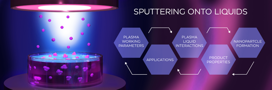
- , Czech Republic 10.3762/bjnano.13.2 Abstract Sputter deposition of atoms onto liquid substrates aims at producing colloidal dispersions of small monodisperse ultrapure nanoparticles (NPs). Since sputtering onto liquids combines the advantages of the physical vapor deposition technique and classical
- reported data; we will address the influence of the sputtering parameters (sputter power, current, voltage, sputter time, working gas pressure, and the type of sputtering plasma) and host liquid properties (composition, temperature, viscosity, and surface tension) on the NP formation as well as a detailed
- overview of the properties and applications of the produced NPs. Keywords: low-pressure plasmas; magnetron; nanoparticles; nanoparticle formation; sputtering; sputtering onto liquids; Introduction According to the general terminology, nanoparticles (NPs) are objects that have a size of less than 100 nm


Topographic signatures and manipulations of Fe atoms, CO molecules and NaCl islands on superconducting Pb(111)
Beilstein J. Nanotechnol. 2022, 13, 1–9, doi:10.3762/bjnano.13.1

- Sample preparation The Pb(111) single crystal, purchased from Mateck GmbH, was cleaned by several sputtering and annealing cycles in ultra-high vacuum (UHV). CO dosing on the cold substrate was done in the microscope chamber by increasing the pressure via a leak valve up to p ≈ 1 × 10⁻⁷ mbar for one
- ) and Pb(110) Figure 1 shows STM images of CO molecules adsorbed on Pb(111). With a lattice parameter of aPb = 4.95 Å, the height of monoatomic steps of the Pb(111) surface is expected to be hPb = = 2.85 Å. Experimentally, a pristine Pb(111) sample (Figure 1a) shows, after sputtering and annealing
- nm with an apparent depression of 0.14 Å. They result from the interference of bulk electrons with trapped subsurface Ar gas bubbles after sputtering [52][53]. After CO dosing in the microscope chamber (see section “Sample preparation”), a coverage of 0.1–0.2 monolayers is expected to adsorb on the


Chemical vapor deposition of germanium-rich CrGex nanowires
Beilstein J. Nanotechnol. 2021, 12, 1365–1371, doi:10.3762/bjnano.12.100

- species, Ar+ ion sputtering was used. The initial atomic elemental ratio was [Cr]/[Ge]/[O] = 1:7.33:11.61; after 90 s of Ar+ ion sputtering the ratio was [Cr]/[Ge]/[O] = 1:4.41:2.43. The presence of oxygen indicated oxidation after the experiment. The [Cr]/[Ge] atomic elemental ratio of 1:4.41 was
- 5.0 × 10⁻⁷ Pa) was used with a polychromatic Mg X-ray source (Mg Kα, 1253.4 eV). A standard superficial surface sputtering with Ar+ ions was applied using 1 kV of acceleration voltage. The Shirley background was subtracted for all spectra. The morphology of each sample was analyzed by a scanning
- (b) the Cr 2p3/2 region after 90 s of Ar+ ion sputtering. (a) I–V characteristics of the nanowire–deposit system; (b) SEM image of a contacted single CrGex nanowire before the resistivity measurement. Supporting Information Supporting Information File 94: Analysis of CrGex nanowires, experimental


Nonmonotonous temperature dependence of Shapiro steps in YBCO grain boundary junctions
Beilstein J. Nanotechnol. 2021, 12, 1279–1285, doi:10.3762/bjnano.12.95

- discussed, and the measurement results are compared with the results of numerical calculations. Experimental Setup and Numerical Model The samples of grain boundary Josephson junctions were fabricated by on-axis dc magnetron sputtering [28][29][30][31] of YBa2Cu3O7−δ (YBCO) film on the surface of 24°[001


Plasmon-enhanced photoluminescence from TiO2 and TeO2 thin films doped by Eu3+ for optoelectronic applications
Beilstein J. Nanotechnol. 2021, 12, 1271–1278, doi:10.3762/bjnano.12.94

- thermal annealing of the gold thin film. Thermal dewetting of gold film results in spherical gold nanostructures with average dimensions of 50 nm. Both, luminescent TiO2:Eu and TeO2:Eu films were deposited by RF magnetron sputtering from mosaic targets. The morphology of the gold nanostructures was
- ethanol and dried at 50 °C. Plasmonic nanostructures were prepared by thermal dewetting of gold thin films. Thin Au films with a thickness of 2.8 nm were deposited using a tabletop DC magnetron sputtering coater (EM SCD 500, Leica) in pure Ar plasma (argon, Air Products, 99.999%) at a pressure of 0.2 Pa
- was conducted at 200 °C. The second kind of dielectric layer was TiO2. It was prepared by radio frequency (RF) reactive magnetron sputtering using an Omicron Nanotechnology four targets sputter system. A Ti target (99.9%) was sputtered in an argon–oxygen atmosphere (Ar/O2 flow ratio: 5 sccm:30 sccm


Is the Ne operation of the helium ion microscope suitable for electron backscatter diffraction sample preparation?
Beilstein J. Nanotechnol. 2021, 12, 965–983, doi:10.3762/bjnano.12.73

- interaction types is illustrated in Figure 1. The ions, irrespective of the ion species, interact with the sample atoms via nuclear and electronic interactions. The electronic interactions lead to secondary electron emission and polymerization while the nuclear interactions lead to sputtering, sample atom
- ideal candidate for sputtering applications. Neon interacts almost equally via electronic and nuclear interactions at those energies and allows for fast material removal per incident ion. As an inert ion species, neon has been proven advantageous for processing semiconducting materials in which Ga
- induces sample alterations and material behavior changes due to doping [22]. Not all nuclear interactions lead to sputtering. If the sample atom cannot be removed from the sample because of insufficient energy transfer or because the sample atom cannot exit the sample due to its sub-surface position


Uniform arrays of gold nanoelectrodes with tuneable recess depth
Beilstein J. Nanotechnol. 2021, 12, 957–964, doi:10.3762/bjnano.12.72

- deposited by magnetron sputtering onto the bottom side of the AAO template. Electrodeposition of metals into channels of the AAO template was performed in a three-electrode cell with an electrodeposition area of 0.2 cm2 and a volume of 50 mL at room temperature in a potentiostatic mode. A platinum ring


In situ transport characterization of magnetic states in Nb/Co superconductor/ferromagnet heterostructures
Beilstein J. Nanotechnol. 2021, 12, 913–923, doi:10.3762/bjnano.12.68

- layers composing a single pseudo spin valve. A more complex S2, Nb(50 nm)/[Co(1.5 nm)/Nb(6 nm)/Co(2.5 nm)/Nb(6 mn)]3Co(1.5 nm)/Nb(6 nm)/Si (the structure in square brackets is repeated three times) has five Co layers. MLs are deposited by magnetron sputtering in a single deposition cycle without breaking


9.1% efficient zinc oxide/silicon solar cells on a 50 μm thick Si absorber
Beilstein J. Nanotechnol. 2021, 12, 766–774, doi:10.3762/bjnano.12.60

- environmentally friendly solar cells are cells based on zinc oxide (ZnO). ZnO thin films can be obtained using many technologies, including molecular beam epitaxy, RF magnetron sputtering, pulsed laser deposition, chemical vapor deposition, and atomic layer deposition (ALD) [3]. ALD attracts the attention of many
- deposited as a low-resistivity ohmic contact via sputtering. To improve the contact parameters, the samples were annealed at 500 °C for 5 min in argon atmosphere via rapid thermal processing. Si/Al substrates were prepared in two different ways, A and B. On the surface of sample A, zinc oxide nanorods
- hole of 0.1 cm in diameter was placed on the samples. Then, Al was deposited on top via sputtering. The simple point contact was used on top of the structure. To improve the light collection from full-size ZnO/Si SCs, grid-like contacts should be used. The resulting solar cell structures are shown in


Recent progress in actuation technologies of micro/nanorobots
Beilstein J. Nanotechnol. 2021, 12, 756–765, doi:10.3762/bjnano.12.59

- sputtering, and the actuation mechanism of the robot is self-electrophoretic. Because the shape of the micro/nanorobot was different, the Z-shaped micro/nanorobot can use two opposite forces on different sides to actuate rotation. In addition, new research has found that the measured actuation force is of


A review of defect engineering, ion implantation, and nanofabrication using the helium ion microscope
Beilstein J. Nanotechnol. 2021, 12, 633–664, doi:10.3762/bjnano.12.52

- with neon, sputtering at higher rates is made possible while retaining a small probe size. This has also opened the door to in situ materials analysis in the HIM using secondary ion mass spectrometry [8]. Further forms of materials analysis using the HIM include techniques based on the collection of
- irradiation effects, such as defect formation and ion implantation, are used to locally change the properties of the material, and at higher doses, nanofabrication is performed using localized material removal (by sputtering) or addition (by gas-assisted deposition). Sometimes, lower-dose irradiation effects
- depth in the material (see Figure 1b). This means that defect creation, implantation, sputtering, and deposition can all be very localized. Correspondingly, the secondary electrons that are generated (escape depth of a few nanometers) emanate from an area not that much larger than the original impact


High-yield synthesis of silver nanowires for transparent conducting PET films
Beilstein J. Nanotechnol. 2021, 12, 624–632, doi:10.3762/bjnano.12.51

- toxic composition. Moreover, the sputtering process is time-consuming and sputtering make the films brittle, which limits the application in flexible applications [5]. Numerous materials are under consideration to overcome these challenges. In the past few years, certain materials, such as graphene


Impact of GaAs(100) surface preparation on EQE of AZO/Al2O3/p-GaAs photovoltaic structures
Beilstein J. Nanotechnol. 2021, 12, 578–592, doi:10.3762/bjnano.12.48

- -cycles. Each multi-cycle, in turn, consisted of one aluminum oxide creation cycle (TMA + H2O) and 24 cycles of zinc oxide deposition (diethylzinc/Zn(C2H5)2, DEZ, CAS:557-20-0) + H2O [2]. In the final fabrication process, a top point contact was deposited (70 nm) by aluminum-target sputtering (Kurt J
- , were chosen for detailed studies. The results of elemental content are collected in Table 1 for A2 (left) and B1 (right) samples as a function of the sputtering time. Due a very wide interface we did not convert the sputtering time to nanometers. The difference in the width of the interface among the
- analyzed samples is most striking when comparing the data in Table 1. The substrate was revealed after 96 min of sputtering of sample A2 but already after 64 min of sputtering of sample B1. The changes in elemental concentration appeared after 30 min of sputtering. In the case of A2, first the changes in


Local stiffness and work function variations of hexagonal boron nitride on Cu(111)
Beilstein J. Nanotechnol. 2021, 12, 559–565, doi:10.3762/bjnano.12.46

- acquisition. Sample preparation: A Cu(111) single crystal (MaTeck GmbH) is cleaned via repeated cycles of Ar-ion sputtering at room temperature followed by annealing to 1020 K in an ultrahigh-vacuum preparation chamber. A partial layer of h-BN is grown by chemical vapour deposition by heating the Cu(111


Influence of electrospray deposition on C60 molecular assemblies
Beilstein J. Nanotechnol. 2021, 12, 552–558, doi:10.3762/bjnano.12.45

- ) single crystals (Mateck GmbH) were prepared under UHV conditions by several cycles of Ar+ sputtering and annealing at 750 K. KBr(001) crystals (Mateck GmbH) were prepared either by cleavage in air and quick introduction in UHV or by cleavage under UHV conditions. Subsequently, annealing at 350 K for 2 h
- nm, and f2 = 1 MHz, A2 = 400–800 pm. Their preparation consisted of annealing for 1 h at 400 K followed by tip Ar+ sputtering for 90 s at 680 eV at an Ar+ pressure of 3 × 10⁻⁶ mbar. The base pressure of the UHV system during AFM measurements is maintained at 2 × 10⁻¹¹ mbar. Electrospray deposition


Determining amplitude and tilt of a lateral force microscopy sensor
Beilstein J. Nanotechnol. 2021, 12, 517–524, doi:10.3762/bjnano.12.42

- , Germany) operating in ultra-high vacuum at 5.6 K equipped with a qPlus sensor [25]. The sensor was equipped with an etched tungsten tip, which was repeatedly poked into a Cu(111) surface to generate well-defined tip apex configurations. Cu(111) was cleaned by standard sputtering and annealing cycles


