Search results
Search for "alkanes" in Full Text gives 110 result(s) in Beilstein Journal of Organic Chemistry.
Visible-light-mediated copper photocatalysis for organic syntheses
- Yajing Zhang,
- Qian Wang,
- Zongsheng Yan,
- Donglai Ma and
- Yuguang Zheng
Beilstein J. Org. Chem. 2021, 17, 2520–2542, doi:10.3762/bjoc.17.169

- functionalization of stable alkanes C(sp3)–H is generally difficult. In 2020, the König group [97] explored the photoinduced copperII catalyzed N–H alkylation of a broad range of nitrogen-containing compounds 61 with unactivated alkanes 62. A tert-butoxy radical abstracted a hydrogen atom from the alkane via the

Graphical Abstract

Scheme 1: Photoredox catalysis mechanism of [Ru(bpy)3]2+.

Scheme 2: Photoredox catalysis mechanism of CuI.

Scheme 3: Ligands and CuI complexes.

Scheme 4: Mechanism of CuI-based photocatalysis.

Scheme 5: Mechanisms of CuI–substrate complexes.

Scheme 6: Mechanism of CuII-base photocatalysis.

Scheme 7: Olefinic C–H functionalization and allylic alkylation.

Scheme 8: Cross-coupling of unactivated alkenes and CF3SO2Cl.

Scheme 9: Chlorosulfonylation/cyanofluoroalkylation of alkenes.

Scheme 10: Hydroamination of alkenes.

Scheme 11: Cross-coupling reaction of alkenes, alkyl halides with nucleophiles.

Scheme 12: Cross-coupling of alkenes with oxime esters.

Scheme 13: Oxo-azidation of vinyl arenes.

Scheme 14: Azidation/difunctionalization of vinyl arenes.

Scheme 15: Photoinitiated copper-catalyzed Sonogashira reaction.

Scheme 16: Alkyne functionalization reactions.

Scheme 17: Alkynylation of dihydroquinoxalin-2-ones with terminal alkynes.

Scheme 18: Decarboxylative alkynylation of redox-active esters.

Scheme 19: Aerobic oxidative C(sp)–S coupling reaction.

Scheme 20: Copper-catalyzed alkylation of carbazoles with alkyl halides.

Scheme 21: C–N coupling of organic halides with amides and aliphatic amines.

Scheme 22: Copper-catalyzed C–X (N, S, O) bond formation reactions.

Scheme 23: Arylation of C(sp2)–H bonds of azoles.

Scheme 24: C–C cross-coupling of aryl halides and heteroarenes.

Scheme 25: Benzylic or α-amino C–H functionalization.

Scheme 26: α-Amino C–H functionalization of aromatic amines.

Scheme 27: C–H functionalization of aromatic amines.

Scheme 28: α-Amino-C–H and alkyl C–H functionalization reactions.

Scheme 29: Other copper-photocatalyzed reactions.

Scheme 30: Cross-coupling of oxime esters with phenols or amines.

Scheme 31: Alkylation of heteroarene N-oxides.
Photoredox catalysis in nickel-catalyzed C–H functionalization
- Lusina Mantry,
- Rajaram Maayuri,
- Vikash Kumar and
- Parthasarathy Gandeepan
Beilstein J. Org. Chem. 2021, 17, 2209–2259, doi:10.3762/bjoc.17.143

- quantities of sodium tungstate were found to be beneficial for the formation of the desired cross-coupling products 77. The authors’ investigations suggested that tungstate is acting as a base rather than a photocatalyst. A variety of C–H substrates including unactivated alkanes, amines, and ethers were
- xanthone as the photocatalyst and NiCl2·6H2O as the nickel catalyst can efficiently catalyze the transformation of methylarenes 25 into arylacetic acids 91 under UV light irradiation (Scheme 47). Furthermore, the authors also applied this methodology to functionalize unactivated alkanes such as cyclohexane
- alkanes 16, alkenes 92, and aryl bromides 3 (Scheme 48) [140]. Here, TBADT enables the generation of alkyl radicals from various alkane substrates via a HAT process under near-ultraviolet light irradiation. Both cyclic and linear alkanes were found to be suitable under the reaction conditions. Linear

Graphical Abstract

Scheme 1: Nickel-catalyzed cross-coupling versus C‒H activation.

Figure 1: Oxidative and reductive quenching cycles of a photocatalyst. [PC] = photocatalyst, A = acceptor, D ...

Scheme 2: Photoredox nickel-catalyzed C(sp3)–H arylation of dimethylaniline (1a).

Scheme 3: Photoredox nickel-catalyzed arylation of α-amino, α-oxy and benzylic C(sp3)‒H bonds with aryl bromi...

Figure 2: Proposed catalytic cycle for the photoredox-mediated HAT and nickel catalysis enabled C(sp3)‒H aryl...

Scheme 4: Photoredox arylation of α-amino C(sp3)‒H bonds with aryl iodides.

Figure 3: Proposed mechanism for photoredox nickel-catalyzed α-amino C‒H arylation with aryl iodides.

Scheme 5: Nickel-catalyzed α-oxy C(sp3)−H arylation of cyclic and acyclic ethers.

Figure 4: Proposed catalytic cycle for the C(sp3)−H arylation of cyclic and acyclic ethers.

Scheme 6: Photochemical nickel-catalyzed C–H arylation of ethers.

Figure 5: Proposed catalytic cycle for the nickel-catalyzed arylation of ethers with aryl bromides.

Scheme 7: Nickel-catalyzed α-amino C(sp3)‒H arylation with aryl tosylates.

Scheme 8: Arylation of α-amino C(sp3)‒H bonds by in situ generated aryl tosylates from phenols.

Scheme 9: Formylation of aryl chlorides through redox-neutral 2-functionalization of 1,3-dioxolane (13).

Scheme 10: Photochemical C(sp3)–H arylation via a dual polyoxometalate HAT and nickel catalytic manifold.

Figure 6: Proposed mechanism for C(sp3)–H arylation through dual polyoxometalate HAT and nickel catalytic man...

Scheme 11: Photochemical nickel-catalyzed α-hydroxy C‒H arylation.

Scheme 12: Photochemical synthesis of fluoxetine (21).

Scheme 13: Photochemical nickel-catalyzed allylic C(sp3)‒H arylation with aryl bromides.

Figure 7: Proposed mechanism for the photochemical nickel-catalyzed allylic C(sp3)‒H arylation with aryl brom...

Scheme 14: Photochemical C(sp3)‒H arylation by the synergy of ketone HAT catalysis and nickel catalysis.

Figure 8: Proposed mechanism for photochemical C(sp3)‒H arylation by the synergy of ketone HAT catalysis and ...

Scheme 15: Benzophenone- and nickel-catalyzed photoredox benzylic C–H arylation.

Scheme 16: Benzaldehyde- and nickel-catalyzed photoredox C(sp3)–H arylation.

Scheme 17: Photoredox and nickel-catalyzed enantioselective benzylic C–H arylation.

Figure 9: Proposed mechanism for the photoredox and nickel-catalyzed enantioselective benzylic C–H arylation.

Scheme 18: Photoredox nickel-catalyzed α-(sp3)‒H arylation of secondary benzamides with aryl bromides.

Scheme 19: Enantioselective sp3 α-arylation of benzamides.

Scheme 20: Nickel-catalyzed decarboxylative vinylation/C‒H arylation of cyclic oxalates.

Figure 10: Proposed mechanism for the nickel-catalyzed decarboxylative vinylation/C‒H arylation of cyclic oxal...

Scheme 21: C(sp3)−H arylation of bioactive molecules using mpg-CN photocatalysis and nickel catalysis.

Figure 11: Proposed mechanism for the mpg-CN/nickel photocatalytic C(sp3)–H arylation.

Scheme 22: Nickel-catalyzed synthesis of 1,1-diarylalkanes from alkyl bromides and aryl bromides.

Figure 12: Proposed mechanism for photoredox nickel-catalyzed C(sp3)–H alkylation via polarity-matched HAT.

Scheme 23: Photoredox nickel-catalyzed C(sp3)‒H alkylation via polarity-matched HAT.

Scheme 24: Benzaldehyde- and nickel-catalyzed photoredox C(sp3)‒H alkylation of ethers.

Scheme 25: Benzaldehyde- and nickel-catalyzed photoredox C(sp3)‒H alkylation of amides and thioethers.

Scheme 26: Photoredox and nickel-catalyzed C(sp3)‒H alkylation of benzamides with alkyl bromides.

Scheme 27: CzIPN and nickel-catalyzed C(sp3)‒H alkylation of ethers with alkyl bromides.

Figure 13: Proposed mechanism for the CzIPN and nickel-catalyzed C(sp3)‒H alkylation of ethers.

Scheme 28: Nickel/photoredox-catalyzed methylation of (hetero)aryl chlorides and acid chlorides using trimethy...

Figure 14: Proposed catalytic cycle for the nickel/photoredox-catalyzed methylation of (hetero)aryl chlorides ...

Scheme 29: Photochemical nickel-catalyzed C(sp3)–H methylations.

Scheme 30: Photoredox nickel catalysis-enabled alkylation of unactivated C(sp3)–H bonds with alkyl bromides.

Scheme 31: Photochemical C(sp3)–H alkenylation with alkenyl tosylates.

Scheme 32: Photoredox nickel-catalyzed hydroalkylation of internal alkynes.

Figure 15: Proposed mechanism for the photoredox nickel-catalyzed hydroalkylation of internal alkynes.

Scheme 33: Photoredox nickel-catalyzed hydroalkylation of activated alkynes with C(sp3)−H bonds.

Scheme 34: Allylation of unactivated C(sp3)−H bonds with allylic chlorides.

Scheme 35: Photochemical nickel-catalyzed α-amino C(sp3)–H allylation of secondary amides with trifluoromethyl...

Scheme 36: Photoredox δ C(sp3)‒H allylation of secondary amides with trifluoromethylated alkenes.

Scheme 37: Photoredox nickel-catalyzed acylation of α-amino C(sp3)‒H bonds of N-arylamines.

Figure 16: Proposed mechanism for the photoredox nickel-catalyzed acylation of α-amino C(sp3)–H bonds of N-ary...

Scheme 38: Photocatalytic α‑acylation of ethers with acid chlorides.

Figure 17: Proposed mechanism for the photocatalytic α‑acylation of ethers with acid chlorides.

Scheme 39: Photoredox and nickel-catalyzed C(sp3)‒H esterification with chloroformates.

Scheme 40: Photoredox nickel-catalyzed dehydrogenative coupling of benzylic and aldehydic C–H bonds.

Figure 18: Proposed reaction pathway for the photoredox nickel-catalyzed dehydrogenative coupling of benzylic ...

Scheme 41: Photoredox nickel-catalyzed enantioselective acylation of α-amino C(sp3)–H bonds with carboxylic ac...

Scheme 42: Nickel-catalyzed C(sp3)‒H acylation with N-acylsuccinimides.

Figure 19: Proposed mechanism for the nickel-catalyzed C(sp3)–H acylation with N-acylsuccinimides.

Scheme 43: Nickel-catalyzed benzylic C–H functionalization with acid chlorides 45.

Scheme 44: Photoredox nickel-catalyzed benzylic C–H acylation with N-acylsuccinimides 84.

Scheme 45: Photoredox nickel-catalyzed acylation of indoles 86 with α-oxoacids 87.

Scheme 46: Nickel-catalyzed aldehyde C–H functionalization.

Figure 20: Proposed catalytic cycle for the photoredox nickel-catalyzed aldehyde C–H functionalization.

Scheme 47: Photoredox carboxylation of methylbenzenes with CO2.

Figure 21: Proposed mechanism for the photoredox carboxylation of methylbenzenes with CO2.

Scheme 48: Decatungstate photo-HAT and nickel catalysis enabled alkene difunctionalization.

Figure 22: Proposed catalytic cycle for the decatungstate photo-HAT and nickel catalysis enabled alkene difunc...

Scheme 49: Diaryl ketone HAT catalysis and nickel catalysis enabled dicarbofunctionalization of alkenes.

Figure 23: Proposed catalytic mechanism for the diaryl ketone HAT catalysis and nickel catalysis enabled dicar...

Scheme 50: Overview of photoredox nickel-catalyzed C–H functionalizations.
Recent advances in the syntheses of anthracene derivatives
- Giovanni S. Baviera and
- Paulo M. Donate
Beilstein J. Org. Chem. 2021, 17, 2028–2050, doi:10.3762/bjoc.17.131

- [11][12], the 2,2’-bianthracene derivative 3 provides a green and fluorescent OLED [13], 2,2’-bianthracenyl (4) has been employed as an organic semiconductor in an OFET device [14], and di-n-alkoxyanthracenes have gelling properties with diverse solvents, mainly alkanes and alcohols [4]. Furthermore

Graphical Abstract

Figure 1: Examples of anthracene derivatives and their applications.

Scheme 1: Rhodium-catalyzed oxidative coupling reactions of arylboronic acids with internal alkynes.

Scheme 2: Rhodium-catalyzed oxidative benzannulation reactions of 1-adamantoyl-1-naphthylamines with internal...

Scheme 3: Gold/bismuth-catalyzed cyclization of o-alkynyldiarylmethanes.

Scheme 4: [2 + 2 + 2] Cyclotrimerization reactions with alkynes/nitriles in the presence of nickel and cobalt...

Scheme 5: Cobalt-catalyzed [2 + 2 + 2] cyclotrimerization reactions with bis(trimethylsilyl)acetylene (23).

Scheme 6: [2 + 2 + 2] Alkyne-cyclotrimerization reactions catalyzed by a CoCl2·6H2O/Zn reagent.

Scheme 7: Pd(II)-catalyzed sp3 C–H alkenylation of diphenyl carboxylic acids with acrylates.

Scheme 8: Pd(II)-catalyzed sp3 C–H arylation with o-tolualdehydes and aryl iodides.

Scheme 9: Alkylation of arenes with aromatic aldehydes in the presence of acetyl bromide and ZnBr2/SiO2.

Scheme 10: BF3·H2O-catalyzed hydroxyalkylation of arenes with aromatic dialdehyde 44.

Scheme 11: Bi(OTf)3-promoted Friedel–Crafts alkylation of triarylmethanes and aromatic acylals and of arenes a...

Scheme 12: Reduction of anthraquinones by using Zn/pyridine or Zn/NaOH reductive methods.

Scheme 13: Two-step route to novel substituted Indenoanthracenes.

Scheme 14: Synthesis of 1,8-diarylanthracenes through Suzuki–Miyaura coupling reaction in the presence of Pd-P...

Scheme 15: Synthesis of five new substituted anthracenes by using LAH as reducing agent.

Scheme 16: One-pot procedure to synthesize substituted 9,10-dicyanoanthracenes.

Scheme 17: Reduction of bromoanthraquinones with NaBH4 in alkaline medium.

Scheme 18: In(III)-catalyzed reductive-dehydration intramolecular cycloaromatization of 2-benzylic aromatic al...

Scheme 19: Acid-catalyzed cyclization of new O-protected ortho-acetal diarylmethanols.

Scheme 20: Lewis acid-mediated regioselective cyclization of asymmetric diarylmethine dipivalates and diarylme...

Scheme 21: BF3·OEt2/CF3SO3H-mediated cyclodehydration reactions of 2-(arylmethyl)benzaldehydes and 2-(arylmeth...

Scheme 22: Synthesis of 2,3,6,7-anthracenetetracarbonitrile (90) by double Wittig reaction followed by deprote...

Scheme 23: Homo-elongation protocol for the synthesis of substituted acene diesters/dinitriles.

Scheme 24: Synthesis of two new parental BN anthracenes via borylative cyclization.

Scheme 25: Synthesis of substituted anthracenes from a bifunctional organomagnesium alkoxide.

Scheme 26: Palladium-catalyzed tandem C–H activation/bis-cyclization of propargylic carbonates.

Scheme 27: Ruthenium-catalyzed C–H arylation of acetophenone derivatives with arenediboronates.

Scheme 28: Pd-catalyzed intramolecular cyclization of (Z,Z)-p-styrylstilbene derivatives.

Scheme 29: AuCl-catalyzed double cyclization of diiodoethynylterphenyl compounds.

Scheme 30: Iodonium-induced electrophilic cyclization of terphenyl derivatives.

Scheme 31: Oxidative photocyclization of 1,3-distyrylbenzene derivatives.

Scheme 32: Oxidative cyclization of 2,3-diphenylnaphthalenes.

Scheme 33: Suzuki-Miyaura/isomerization/ring closing metathesis strategy to synthesize benz[a]anthracenes.

Scheme 34: Green synthesis of oxa-aza-benzo[a]anthracene and oxa-aza-phenanthrene derivatives.

Scheme 35: Triple benzannulation of substituted naphtalene via a 1,3,6-naphthotriyne synthetic equivalent.

Scheme 36: Zinc iodide-catalyzed Diels–Alder reactions with 1,3-dienes and aroyl propiolates followed by intra...

Scheme 37: H3PO4-promoted intramolecular cyclization of substituted benzoic acids.

Scheme 38: Palladium-catalyzed intermolecular direct acylation of aromatic aldehydes and o-iodoesters.

Scheme 39: Cycloaddition/oxidative aromatization of quinone and β-enamino esters.

Scheme 40: ʟ-Proline-catalyzed [4 + 2] cycloaddition reaction of naphthoquinones and α,β-unsaturated aldehydes....

Scheme 41: Iridium-catalyzed [2 + 2 + 2] cycloaddition of a 1,2-bis(propiolyl)benzene derivative with alkynes.

Scheme 42: Synthesis of several anthraquinone derivatives by using InCl3 and molecular iodine.

Scheme 43: Indium-catalyzed multicomponent reactions employing 2-hydroxy-1,4-naphthoquinone (186), β-naphthol (...

Scheme 44: Synthesis of substituted anthraquinones catalyzed by an AlCl3/MeSO3H system.

Scheme 45: Palladium(II)-catalyzed/visible light-mediated synthesis of anthraquinones.

Scheme 46: [4 + 2] Anionic annulation reaction for the synthesis of substituted anthraquinones.
On the application of 3d metals for C–H activation toward bioactive compounds: The key step for the synthesis of silver bullets
- Renato L. Carvalho,
- Amanda S. de Miranda,
- Mateus P. Nunes,
- Roberto S. Gomes,
- Guilherme A. M. Jardim and
- Eufrânio N. da Silva Júnior
Beilstein J. Org. Chem. 2021, 17, 1849–1938, doi:10.3762/bjoc.17.126

- numbers. The V(II) and V(V) species are reducing and oxidizing agents, respectively, whereas V(IV) is often encountered, mainly in the form of dioxovanadium ion VO2+ center [76]. Vanadium-based compounds have been reported to mediate the oxidation of alkanes to alcohols and ketones [76]. The reactions are
- have been used as additives in these reactions and are suggested to act as ligands, assist proton transfer and promote the formation of oligovanadates by decreasing the pH value of the solution. The mechanisms of some vanadium-mediated oxidation reactions of alkanes have been studied, most of them
- reaction suggested it goes through a radical pathway. Similar to the oxidation of alkanes to give alcohols and carbonyl compounds, vanadium complexes have been reported to mediate the hydroxylation of arenes, including the obtaining of phenol from benzene. However, most mechanistic studies provided

Graphical Abstract

Scheme 1: Schematic overview of transition metals studied in C–H activation processes.

Scheme 2: (A) Known biological activities related to benzimidazole-based compounds; (B and C) an example of a...

Scheme 3: (A) Known biological activities related to quinoline-based compounds; (B and C) an example of a sca...

Scheme 4: (A) Known biological activities related to sulfur-containing compounds; (B and C) an example of a s...

Scheme 5: (A) Known biological activities related to aminoindane derivatives; (B and C) an example of a scand...

Scheme 6: (A) Known biological activities related to norbornane derivatives; (B and C) an example of a scandi...

Scheme 7: (A) Known biological activities related to aniline derivatives; (B and C) an example of a titanium-...

Scheme 8: (A) Known biological activities related to cyclohexylamine derivatives; (B) an example of an intram...

Scheme 9: (A) Known biologically active benzophenone derivatives; (B and C) photocatalytic oxidation of benzy...

Scheme 10: (A) Known bioactive fluorine-containing compounds; (B and C) vanadium-mediated C(sp3)–H fluorinatio...

Scheme 11: (A) Known biologically active Lythraceae alkaloids; (B) synthesis of (±)-decinine (30).

Scheme 12: (A) Synthesis of (R)- and (S)-boehmeriasin (31); (B) synthesis of phenanthroindolizidines by vanadi...

Scheme 13: (A) Known bioactive BINOL derivatives; (B and C) vanadium-mediated oxidative coupling of 2-naphthol...

Scheme 14: (A) Known antiplasmodial imidazopyridazines; (B) practical synthesis of 41.

Scheme 15: (A) Gold-catalyzed drug-release mechanism using 2-alkynylbenzamides; (B and C) chromium-mediated al...

Scheme 16: (A) Examples of anti-inflammatory benzaldehyde derivatives; (B and C) chromium-mediated difunctiona...

Scheme 17: (A and B) Manganese-catalyzed chemoselective intramolecular C(sp3)–H amination; (C) late-stage modi...

Scheme 18: (A and B) Manganese-catalyzed C(sp3)–H amination; (C) late-stage modification of a leelamine deriva...

Scheme 19: (A) Known bioactive compounds containing substituted N-heterocycles; (B and C) manganese-catalyzed ...

Scheme 20: (A) Known indoles that present GPR40 full agonist activity; (B and C) manganese-catalyzed C–H alkyl...

Scheme 21: (A) Examples of known biaryl-containing drugs; (B and C) manganese-catalyzed C–H arylation through ...

Scheme 22: (A) Known zidovudine derivatives with potent anti-HIV properties; (B and C) manganese-catalyzed C–H...

Scheme 23: (A and B) Manganese-catalyzed C–H organic photo-electrosynthesis; (C) late-stage modification.

Scheme 24: (A) Example of a known antibacterial silylated dendrimer; (B and C) manganese-catalyzed C–H silylat...

Scheme 25: (A and B) Fe-based small molecule catalyst applied for selective aliphatic C–H oxidations; (C) late...

Scheme 26: (A) Examples of naturally occurring gracilioethers; (B) the first total synthesis of gracilioether ...

Scheme 27: (A and B) Selective aliphatic C–H oxidation of amino acids; (C) late-stage modification of proline-...

Scheme 28: (A) Examples of Illicium sesquiterpenes; (B) first chemical synthesis of (+)-pseudoanisatin (80) in...

Scheme 29: (A and B) Fe-catalyzed deuteration; (C) late-stage modification of pharmaceuticals.

Scheme 30: (A and B) Biomimetic Fe-catalyzed aerobic oxidation of methylarenes to benzaldehydes (PMHS, polymet...

Scheme 31: (A) Known tetrahydroquinolines with potential biological activities; (B and C) redox-selective Fe c...

Scheme 32: (A) Known drugs containing a benzofuran unit; (B and C) Fe/Cu-catalyzed tandem O-arylation to acces...

Scheme 33: (A) Known azaindolines that act as M4 muscarinic acetylcholine receptor agonists; (B and C) intramo...

Scheme 34: (A) Known indolinones with anticholinesterase activity; (B and C) oxidative C(sp3)–H cross coupling...

Scheme 35: (A and B) Cobalt-catalyzed C–H alkenylation of C-3-peptide-containing indoles; (C) derivatization b...

Scheme 36: (A) Cobalt-Cp*-catalyzed C–H methylation of known drugs; (B and C) scope of the o-methylated deriva...

Scheme 37: (A) Known lasalocid A analogues; (B and C) three-component cobalt-catalyzed C–H bond addition; (D) ...

Scheme 38: (A and B) Cobalt-catalyzed C(sp2)–H amidation of thiostrepton.

Scheme 39: (A) Known 4H-benzo[d][1,3]oxazin-4-one derivatives with hypolipidemic activity; (B and C) cobalt-ca...

Scheme 40: (A and B) Cobalt-catalyzed C–H arylation of pyrrole derivatives; (C) application for the synthesis ...

Scheme 41: (A) Known 2-phenoxypyridine derivatives with potent herbicidal activity; (B and C) cobalt-catalyzed...

Scheme 42: (A) Natural cinnamic acid derivatives; (B and C) cobalt-catalyzed C–H carboxylation of terminal alk...

Scheme 43: (A and B) Cobalt-catalyzed C–H borylation; (C) application to the synthesis of flurbiprofen.

Scheme 44: (A) Benzothiazoles known to present anticonvulsant activities; (B and C) cobalt/ruthenium-catalyzed...

Scheme 45: (A and B) Cobalt-catalyzed oxygenation of methylene groups towards ketone synthesis; (C) synthesis ...

Scheme 46: (A) Known anticancer tetralone derivatives; (B and C) cobalt-catalyzed C–H difluoroalkylation of ar...

Scheme 47: (A and B) Cobalt-catalyzed C–H thiolation; (C) application in the synthesis of quetiapine (153).

Scheme 48: (A) Known benzoxazole derivatives with anticancer, antifungal, and antibacterial activities; (B and...

Scheme 49: (A and B) Cobalt-catalyzed C–H carbonylation of naphthylamides; (C) BET inhibitors 158 and 159 tota...

Scheme 50: (A) Known bioactive pyrrolo[1,2-a]quinoxalin-4(5H)-one derivatives; (B and C) cobalt-catalyzed C–H ...

Scheme 51: (A) Known antibacterial cyclic sulfonamides; (B and C) cobalt-catalyzed C–H amination of propargyli...

Scheme 52: (A and B) Cobalt-catalyzed intramolecular 1,5-C(sp3)–H amination; (C) late-stage functionalization ...

Scheme 53: (A and B) Cobalt-catalyzed C–H/C–H cross-coupling between benzamides and oximes; (C) late-state syn...

Scheme 54: (A) Known anticancer natural isoquinoline derivatives; (B and C) cobalt-catalyzed C(sp2)–H annulati...

Scheme 55: (A) Enantioselective intramolecular nickel-catalyzed C–H activation; (B) bioactive obtained motifs;...

Scheme 56: (A and B) Nickel-catalyzed α-C(sp3)–H arylation of ketones; (C) application of the method using kno...

Scheme 57: (A and B) Nickel-catalyzed C(sp3)–H acylation of pyrrolidine derivatives; (C) exploring the use of ...

Scheme 58: (A) Nickel-catalyzed C(sp3)–H arylation of dioxolane; (B) library of products obtained from biologi...

Scheme 59: (A) Intramolecular enantioselective nickel-catalyzed C–H cycloalkylation; (B) product examples, inc...

Scheme 60: (A and B) Nickel-catalyzed C–H deoxy-arylation of azole derivatives; (C) late-stage functionalizati...

Scheme 61: (A and B) Nickel-catalyzed decarbonylative C–H arylation of azole derivatives; (C) application of t...

Scheme 62: (A and B) Another important example of nickel-catalyzed C–H arylation of azole derivatives; (C) app...

Scheme 63: (A and B) Another notable example of a nickel-catalyzed C–H arylation of azole derivatives; (C) lat...

Scheme 64: (A and B) Nickel-based metalorganic framework (MOF-74-Ni)-catalyzed C–H arylation of azole derivati...

Scheme 65: (A) Known commercially available benzothiophene-based drugs; (B and C) nickel-catalyzed C–H arylati...

Scheme 66: (A) Known natural tetrahydrofuran-containing substances; (B and C) nickel-catalyzed photoredox C(sp3...

Scheme 67: (A and B) Another notable example of a nickel-catalyzed photoredox C(sp3)–H alkylation/arylation; (...

Scheme 68: (A) Electrochemical/nickel-catalyzed C–H alkoxylation; (B) achieved scope, including three using na...

Scheme 69: (A) Enantioselective photoredox/nickel catalyzed C(sp3)–H arylation; (B) achieved scope, including ...

Scheme 70: (A) Known commercially available trifluoromethylated drugs; (B and C) nickel-catalyzed C–H trifluor...

Scheme 71: (A and B) Stereoselective nickel-catalyzed C–H difluoroalkylation; (C) late-stage functionalization...

Scheme 72: (A) Cu-mediated ortho-amination of oxalamides; (B) achieved scope, including derivatives obtained f...

Scheme 73: (A) Electro-oxidative copper-mediated amination of 8-aminoquinoline-derived amides; (B) achieved sc...

Scheme 74: (A and B) Cu(I)-mediated C–H amination with oximes; (C) derivatization using telmisartan (241) as s...

Scheme 75: (A and B) Cu-mediated amination of aryl amides using ammonia; (C) late-stage modification of proben...

Scheme 76: (A and B) Synthesis of purine nucleoside analogues using copper-mediated C(sp2)–H activation.

Scheme 77: (A) Copper-mediated annulation of acrylamide; (B) achieved scope, including the synthesis of the co...

Scheme 78: (A) Known bioactive compounds containing a naphthyl aryl ether motif; (B and C) copper-mediated eth...

Scheme 79: (A and B) Cu-mediated alkylation of N-oxide-heteroarenes; (C) late-stage modification.

Scheme 80: (A) Cu-mediated cross-dehydrogenative coupling of polyfluoroarenes and alkanes; (B) scope from know...

Scheme 81: (A) Known anticancer acrylonitrile compounds; (B and C) Copper-mediated cyanation of unactivated al...

Scheme 82: (A) Cu-mediated radiofluorination of 8-aminoquinoline-derived aryl amides; (B) achieved scope, incl...

Scheme 83: (A) Examples of natural β-carbolines; (B and C) an example of a zinc-catalyzed C–H functionalizatio...

Scheme 84: (A) Examples of anticancer α-aminophosphonic acid derivatives; (B and C) an example of a zinc-catal...
Methodologies for the synthesis of quaternary carbon centers via hydroalkylation of unactivated olefins: twenty years of advances
- Thiago S. Silva and
- Fernando Coelho
Beilstein J. Org. Chem. 2021, 17, 1565–1590, doi:10.3762/bjoc.17.112

- of the potential of ATR in olefin hydrofunctionalization is the methodology developed by the Liu group [119], in which a carbon-centered radical is generated from simple alkanes instead of the more usual halogenated compounds. The authors reported that, in the presence of dicumyl peroxide (DCP) as a
- radical initiator and a copper salt as an additive, the reaction between unactivated olefins and alkanes (in large excess, 50 mL/mmol) afforded anti-Markovnikov hydroalkylation products at high temperature (110 °C) (Scheme 37). Two examples of the synthesis of quaternary carbon centers were reported using

Graphical Abstract

Figure 1: Some examples of natural products and drugs containing quaternary carbon centers.

Scheme 1: Simplified mechanism for olefin hydrofunctionalization using an electrophilic transition metal as a...

Scheme 2: Selected examples of quaternary carbon centers formed by the intramolecular hydroalkylation of β-di...

Scheme 3: Control experiments and the proposed mechanism for the Pd(II)-catalyzed intermolecular hydroalkylat...

Scheme 4: Intermolecular olefin hydroalkylation of less reactive ketones under Pd(II) catalysis using HCl as ...

Scheme 5: A) Selected examples of Pd(II)-mediated quaternary carbon center synthesis by intermolecular hydroa...

Scheme 6: Selected examples of quaternary carbon center synthesis by gold(III) catalysis. This is the first r...

Scheme 7: Selected examples of inter- (A) and intramolecular (B) olefin hydroalkylations promoted by a silver...

Scheme 8: A) Intermolecular hydroalkylation of N-alkenyl β-ketoamides under Au(I) catalysis in the synthesis ...

Scheme 9: Asymmetric pyrrolidine synthesis through intramolecular hydroalkylation of α-substituted N-alkenyl ...

Scheme 10: Proposed mechanism for the chiral gold(I) complex promotion of the intermolecular olefin hydroalkyl...

Scheme 11: Selected examples of carbon quaternary center synthesis by gold and evidence of catalytic system pa...

Scheme 12: Synthesis of a spiro compound via an aza-Michael addition/olefin hydroalkylation cascade promoted b...

Scheme 13: A selected example of quaternary carbon center synthesis using an Fe(III) salt as a catalyst for th...

Scheme 14: Intermolecular hydroalkylation catalyzed by a cationic iridium complex (Fuji (2019) [47]).

Scheme 15: Generic example of an olefin hydrofunctionalization via MHAT (Shenvi (2016) [51]).

Scheme 16: The first examples of olefin hydrofunctionalization run under neutral conditions (Mukaiyama (1989) [56]...

Scheme 17: A) Aryl olefin dimerization catalyzed by vitamin B12 and triggered by HAT. B) Control experiment to...

Scheme 18: Generic example of MHAT diolefin cycloisomerization and possible competitive pathways. Shenvi (2014...

Scheme 19: Selected examples of the MHAT-promoted cycloisomerization reaction of unactivated olefins leading t...

Scheme 20: Regioselective carbocyclizations promoted by an MHAT process (Norton (2008) [76]).

Scheme 21: Selected examples of quaternary carbon centers synthetized via intra- (A) and intermolecular (B) MH...

Scheme 22: A) Proposed mechanism for the Fe(III)/PhSiH3-promoted radical conjugate addition between olefins an...

Scheme 23: Examples of cascade reactions triggered by HAT for the construction of trans-decalin backbone uniti...

Scheme 24: A) Selected examples of the MHAT-promoted radical conjugate addition between olefins and p-quinone ...

Scheme 25: A) MHAT triggered radical conjugate addition/E1cB/lactonization (in some cases) cascade between ole...

Scheme 26: A) Spirocyclization promoted by Fe(III) hydroalkylation of unactivated olefins. B) Simplified mecha...

Scheme 27: A) Selected examples of the construction of a carbon quaternary center by the MHAT-triggered radica...

Scheme 28: Hydromethylation of unactivated olefins under iron-mediated MHAT (Baran (2015) [95]).

Scheme 29: The hydroalkylation of unactivated olefins via iron-mediated reductive coupling with hydrazones (Br...

Scheme 30: Selected examples of the Co(II)-catalyzed bicyclization of dialkenylarenes through the olefin hydro...

Scheme 31: Proposed mechanism for the bicyclization of dialkenylarenes triggered by a MHAT process (Vanderwal ...

Scheme 32: Enantioconvergent cross-coupling between olefins and tertiary halides (Fu (2018) [108]).

Scheme 33: Proposed mechanism for the Ni-catalyzed cross-coupling reaction between olefins and tertiary halide...

Scheme 34: Proposed catalytic cycles for a MHAT/Ni cross-coupling reaction between olefins and halides (Shenvi...

Scheme 35: Selected examples of the hydroalkylation of olefins by a dual catalytic Mn/Ni system (Shenvi (2019) ...

Scheme 36: A) Selected examples of quaternary carbon center synthesis by reductive atom transfer; TBC: 4-tert-...

Scheme 37: A) Selected examples of quaternary carbon centers synthetized by radical addition to unactivated ol...

Scheme 38: A) Selected examples of organophotocatalysis-mediated radical polyene cyclization via a PET process...

Scheme 39: A) Sc(OTf)3-mediated carbocyclization approach for the synthesis of vicinal quaternary carbon cente...

Scheme 40: Scope of the Lewis acid-catalyzed methallylation of electron-rich styrenes. Method A: B(C6F5)3 (5.0...

Scheme 41: The proposed mechanism for styrene methallylation (Oestreich (2019) [123]).
A comprehensive review of flow chemistry techniques tailored to the flavours and fragrances industries
- Guido Gambacorta,
- James S. Sharley and
- Ian R. Baxendale
Beilstein J. Org. Chem. 2021, 17, 1181–1312, doi:10.3762/bjoc.17.90


Graphical Abstract

Figure 1: Representative shares of the global F&F market (2018) segmented on their applications [1].

Figure 2: General structure of an international fragrance company [2].

Figure 3: The Michael Edwards fragrance wheel.

Figure 4: Examples of oriental (1–3), woody (4–7), fresh (8–10), and floral (11 and 12) notes.

Figure 5: A basic depiction of batch vs flow.

Scheme 1: Examples of reactions for which flow processing outperforms batch.

Scheme 2: Some industrially important aldol-based transformations.

Scheme 3: Biphasic continuous aldol reactions of acetone and various aldehydes.

Scheme 4: Aldol synthesis of 43 in flow using LiHMDS as the base.

Scheme 5: A semi-continuous synthesis of doravirine (49) involving a key aldol reaction.

Scheme 6: Enantioselective aldol reaction using 5-(pyrrolidin-2-yl)tetrazole (51) as catalyst in a microreact...

Scheme 7: Gröger's example of asymmetric aldol reaction in aqueous media.

Figure 6: Immobilised reagent column reactor types.

Scheme 8: Photoinduced thiol–ene coupling preparation of silica-supported 5-(pyrrolidin-2-yl)tetrazole 63 and...

Scheme 9: Continuous-flow approach for enantioselective aldol reactions using the supported catalyst 67.

Scheme 10: Ötvös’ employment of a solid-supported peptide aldol catalyst in flow.

Scheme 11: The use of proline tetrazole packed in a column for aldol reaction between cyclohexanone (65) and 2...

Scheme 12: Schematic diagram of an aminosilane-grafted Si-Zr-Ti/PAI-HF reactor for continuous-flow aldol and n...

Scheme 13: Continuous-flow condensation for the synthesis of the intermediate 76 to nabumetone (77) and Microi...

Scheme 14: Synthesis of ψ-Ionone (80) in continuous-flow via aldol condensation between citral (79) and aceton...

Scheme 15: Synthesis of β-methyl-ionones (83) from citral (79) in flow. The steps are separately described, an...

Scheme 16: Continuous-flow synthesis of 85 from 84 described by Gavriilidis et al.

Scheme 17: Continuous-flow scCO2 apparatus for the synthesis of 2-methylpentanal (87) and the self-condensed u...

Scheme 18: Chen’s two-step flow synthesis of coumarin (90).

Scheme 19: Pechmann condensation for the synthesis of 7-hydroxyxcoumarin (93) in flow. The setup extended to c...

Scheme 20: Synthesis of the dihydrojasmonate 35 exploiting nitro derivative proposed by Ballini et al.

Scheme 21: Silica-supported amines as heterogeneous catalyst for nitroaldol condensation in flow.

Scheme 22: Flow apparatus for the nitroaldol condensation of p-hydroxybenzaldehyde (102) to nitrostyrene 103 a...

Scheme 23: Nitroaldol reaction of 64 to 105 employing a quaternary ammonium functionalised PANF.

Scheme 24: Enantioselective nitroaldol condensation for the synthesis of 108 under flow conditions.

Scheme 25: Enatioselective synthesis of 1,2-aminoalcohol 110 via a copper-catalysed nitroaldol condensation.

Scheme 26: Examples of Knoevenagel condensations applied for fragrance components.

Scheme 27: Flow apparatus for Knoevenagel condensation described in 1989 by Venturello et al.

Scheme 28: Knoevenagel reaction using a coated multichannel membrane microreactor.

Scheme 29: Continuous-flow apparatus for Knoevenagel condensation employing sugar cane bagasse as support deve...

Scheme 30: Knoevenagel reaction for the synthesis of 131–135 in flow using an amine-functionalised silica gel. ...

Scheme 31: Continuous-flow synthesis of compound 137, a key intermediate for the synthesis of pregabalin (138)...

Scheme 32: Continuous solvent-free apparatus applied for the synthesis of compounds 140–143 using a TSE. Throu...

Scheme 33: Lewis et al. developed a spinning disc reactor for Darzens condensation of 144 and a ketone to furn...

Scheme 34: Some key industrial applications of conjugate additions in the F&F industry.

Scheme 35: Continuous-flow synthesis of 4-(2-hydroxyethyl)thiomorpholine 1,1-dioxide (156) via double conjugat...

Scheme 36: Continuous-flow system for Michael addition using CsF on alumina as the catalyst.

Scheme 37: Calcium chloride-catalysed asymmetric Michael addition using an immobilised chiral ligand.

Scheme 38: Continuous multistep synthesis for the preparation of (R)-rolipram (173). Si-NH2: primary amine-fun...

Scheme 39: Continuous-flow Michael addition using ion exchange resin Amberlyst® A26.

Scheme 40: Preparation of the heterogeneous catalyst 181 developed by Paixão et al. exploiting Ugi multicompon...

Scheme 41: Continuous-flow system developed by the Paixão’s group for the preparation of Michael asymmetric ad...

Scheme 42: Continuous-flow synthesis of nitroaldols catalysed by supported catalyst 184 developed by Wennemers...

Scheme 43: Heterogenous polystyrene-supported catalysts developed by Pericàs and co-workers.

Scheme 44: PANF-supported pyrrolidine catalyst for the conjugate addition of cyclohexanone (65) and trans-β-ni...

Scheme 45: Synthesis of (−)-paroxetine precursor 195 developed by Ötvös, Pericàs, and Kappe.

Scheme 46: Continuous-flow approach for the 5-step synthesis of (−)-oseltamivir (201) as devised by Hayashi an...

Scheme 47: Continuous-flow enzyme-catalysed Michael addition.

Scheme 48: Continuous-flow copper-catalysed 1,4 conjugate addition of Grignard reagents to enones. Reprinted w...

Scheme 49: A collection of commonly encountered hydrogenation reactions.

Figure 7: The ThalesNano H-Cube® continuous-flow hydrogenator.

Scheme 50: Chemoselective reduction of an α,β-unsaturated ketone using the H-Cube® reactor.

Scheme 51: Incorporation of Lindlar’s catalyst into the H-Cube® reactor for the reduction of an alkyne.

Scheme 52: Continuous-flow semi-hydrogenation of alkyne 208 to 209 using SACs with H-Cube® system.

Figure 8: The standard setups for tube-in-tube gas–liquid reactor units.

Scheme 53: Homogeneous hydrogenation of olefins using a tube-in-tube reactor setup.

Scheme 54: Recyclable heterogeneous flow hydrogenation system.

Scheme 55: Leadbeater’s reverse tube-in-tube hydrogenation system for olefin reductions.

Scheme 56: a) Hydrogenation using a Pd-immobilised microchannel reactor (MCR) and b) a representation of the i...

Scheme 57: Hydrogenation of alkyne 238 exploiting segmented flow in a Pd-immobilised capillary reactor.

Scheme 58: Continuous hydrogenation system for the preparation of cyrene (241) from (−)-levoglucosenone (240).

Scheme 59: Continuous hydrogenation system based on CSMs developed by Hornung et al.

Scheme 60: Chemoselective reduction of carbonyls (ketones over aldehydes) in flow.

Scheme 61: Continuous system for the semi-hydrogenation of 256 and 258, developed by Galarneau et al.

Scheme 62: Continuous synthesis of biodiesel fuel 261 from lignin-derived furfural acetone (260).

Scheme 63: Continuous synthesis of γ-valerolacetone (263) via CTH developed by Pineda et al.

Scheme 64: Continuous hydrogenation of lignin-derived biomass (products 265, 266, and 267) using a sustainable...

Scheme 65: Ru/C or Rh/C-catalysed hydrogenation of arene in flow as developed by Sajiki et al.

Scheme 66: Polysilane-immobilized Rh–Pt-catalysed hydrogenation of arenes in flow by Kobayashi et al.

Scheme 67: High-pressure in-line mixing of H2 for the asymmetric reduction of 278 at pilot scale with a 73 L p...

Figure 9: Picture of the PFR employed at Eli Lilly & Co. for the continuous hydrogenation of 278 [287]. Reprinted ...

Scheme 68: Continuous-flow asymmetric hydrogenation using Oppolzer's sultam 280 as chiral auxiliary.

Scheme 69: Some examples of industrially important oxidation reactions in the F&F industry. CFL: compact fluor...

Scheme 70: Gold-catalysed heterogeneous oxidation of alcohols in flow.

Scheme 71: Uozumi’s ARP-Pt flow oxidation protocol.

Scheme 72: High-throughput screening of aldehyde oxidation in flow using an in-line GC.

Scheme 73: Permanganate-mediated Nef oxidation of nitroalkanes in flow with the use of in-line sonication to p...

Scheme 74: Continuous-flow aerobic anti-Markovnikov Wacker oxidation.

Scheme 75: Continuous-flow oxidation of 2-benzylpyridine (312) using air as the oxidant.

Scheme 76: Continuous-flow photo-oxygenation of monoterpenes.

Scheme 77: A tubular reactor design for flow photo-oxygenation.

Scheme 78: Glucose oxidase (GOx)-mediated continuous oxidation of glucose using compressed air and the FFMR re...

Scheme 79: Schematic continuous-flow sodium hypochlorite/TEMPO oxidation of alcohols.

Scheme 80: Oxidation using immobilised TEMPO (344) was developed by McQuade et al.

Scheme 81: General protocol for the bleach/catalytic TBAB oxidation of aldehydes and alcohols.

Scheme 82: Continuous-flow PTC-assisted oxidation using hydrogen peroxide. The process was easily scaled up by...

Scheme 83: Continuous-flow epoxidation of cyclohexene (348) and in situ preparation of m-CPBA.

Scheme 84: Continuous-flow epoxidation using DMDO as oxidant.

Scheme 85: Mukayama aerobic epoxidation optimised in flow mode by the Favre-Réguillon group.

Scheme 86: Continuous-flow asymmetric epoxidation of derivatives of 359 exploiting a biomimetic iron catalyst.

Scheme 87: Continuous-flow enzymatic epoxidation of alkenes developed by Watts et al.

Scheme 88: Engineered multichannel microreactor for continuous-flow ozonolysis of 366.

Scheme 89: Continuous-flow synthesis of the vitamin D precursor 368 using multichannel microreactors. MFC: mas...

Scheme 90: Continuous ozonolysis setup used by Kappe et al. for the synthesis of various substrates employing ...

Scheme 91: Continuous-flow apparatus for ozonolysis as developed by Ley et al.

Scheme 92: Continuous-flow ozonolysis for synthesis of vanillin (2) using a film-shear flow reactor.

Scheme 93: Examples of preparative methods for ajoene (386) and allicin (388).

Scheme 94: Continuous-flow oxidation of thioanisole (389) using styrene-based polymer-supported peroxytungstat...

Scheme 95: Continuous oxidation of thiosulfinates using Oxone®-packed reactor.

Scheme 96: Continuous-flow electrochemical oxidation of thioethers.

Scheme 97: Continuous-flow oxidation of 400 to cinnamophenone (235).

Scheme 98: Continuous-flow synthesis of dehydrated material 401 via oxidation of methyl dihydrojasmonate (33).

Scheme 99: Some industrially important transformations involving Grignard reagents.

Scheme 100: Grachev et al. apparatus for continuous preparation of Grignard reagents.

Scheme 101: Example of fluidized Mg bed reactor with NMR spectrometer as on-line monitoring system.

Scheme 102: Continuous-flow synthesis of Grignard reagents and subsequent quenching reaction.

Figure 10: Membrane-based, liquid–liquid separator with integrated pressure control [52]. Adapted with permission ...

Scheme 103: Continuous-flow synthesis of 458, an intermediate to fluconazole (459).

Scheme 104: Continuous-flow synthesis of ketones starting from benzoyl chlorides.

Scheme 105: A Grignard alkylation combining CSTR and PFR technologies with in-line infrared reaction monitoring....

Scheme 106: Continuous-flow preparation of 469 from Grignard addition of methylmagnesium bromide.

Scheme 107: Continuous-flow synthesis of Grignard reagents 471.

Scheme 108: Preparation of the Grignard reagent 471 using CSTR and the continuous process for synthesis of the ...

Scheme 109: Continuous process for carboxylation of Grignard reagents in flow using tube-in-tube technology.

Scheme 110: Continuous synthesis of propargylic alcohols via ethynyl-Grignard reagent.

Scheme 111: Silica-supported catalysed enantioselective arylation of aldehydes using Grignard reagents in flow ...

Scheme 112: Acid-catalysed rearrangement of citral and dehydrolinalool derivatives.

Scheme 113: Continuous stilbene isomerisation with continuous recycling of photoredox catalyst.

Scheme 114: Continuous-flow synthesis of compound 494 as developed by Ley et al.

Scheme 115: Selected industrial applications of DA reaction.

Scheme 116: Multistep flow synthesis of the spirocyclic structure 505 via employing DA cycloaddition.

Scheme 117: Continuous-flow DA reaction developed in a plater flow reactor for the preparation of the adduct 508...

Scheme 118: Continuous-flow DA reaction using a silica-supported imidazolidinone organocatalyst.

Scheme 119: Batch vs flow for the DA reaction of (cyclohexa-1,5-dien-1-yloxy)trimethylsilane (513) with acrylon...

Scheme 120: Continuous-flow DA reaction between 510 and 515 using a shell-core droplet system.

Scheme 121: Continuous-flow synthesis of bicyclic systems from benzyne precursors.

Scheme 122: Continuous-flow synthesis of bicyclic scaffolds 527 and 528 for further development of potential ph...

Scheme 123: Continuous-flow inverse-electron hetero-DA reaction to pyridine derivatives such as 531.

Scheme 124: Comparison between batch and flow for the synthesis of pyrimidinones 532–536 via retro-DA reaction ...

Scheme 125: Continuous-flow coupled with ultrasonic system for preparation of ʟ-ascorbic acid derivatives 539 d...

Scheme 126: Two-step continuous-flow synthesis of triazole 543.

Scheme 127: Continuous-flow preparation of triazoles via CuAAC employing 546-based heterogeneous catalyst.

Scheme 128: Continuous-flow synthesis of compounds 558 through A3-coupling and 560 via AgAAC both employing the...

Scheme 129: Continuous-flow photoinduced [2 + 2] cycloaddition for the preparation of bicyclic derivatives of 5...

Scheme 130: Continuous-flow [2 + 2] and [5 + 2] cycloaddition on large scale employing a flow reactor developed...

Scheme 131: Continuous-flow preparation of the tricyclic structures 573 and 574 starting from pyrrole 570 via [...

Scheme 132: Continuous-flow [2 + 2] photocyclization of cinnamates.

Scheme 133: Continuous-flow preparation of cyclobutane 580 on a 5-plates photoreactor.

Scheme 134: Continuous-flow [2 + 2] photocycloaddition under white LED lamp using heterogeneous PCN as photocat...

Figure 11: Picture of the parallel tube flow reactor (PTFR) "The Firefly" developed by Booker-Milburn et al. a...

Scheme 135: Continuous-flow acid-catalysed [2 + 2] cycloaddition between silyl enol ethers and acrylic esters.

Scheme 136: Continuous synthesis of lactam 602 using glass column reactors.

Scheme 137: In situ generation of ketenes for the Staudinger lactam synthesis developed by Ley and Hafner.

Scheme 138: Application of [2 + 2 + 2] cycloadditions in flow employed by Ley et al.

Scheme 139: Examples of FC reactions applied in F&F industry.

Scheme 140: Continuous-flow synthesis of ibuprofen developed by McQuade et al.

Scheme 141: The FC acylation step of Jamison’s three-step ibuprofen synthesis.

Scheme 142: Synthesis of naphthalene derivative 629 via FC acylation in microreactors.

Scheme 143: Flow system for rapid screening of catalysts and reaction conditions developed by Weber et al.

Scheme 144: Continuous-flow system developed by Buorne, Muller et al. for DSD optimisation of the FC acylation ...

Scheme 145: Continuous-flow FC acylation of alkynes to yield β-chlorovinyl ketones such as 638.

Scheme 146: Continuous-flow synthesis of tonalide (619) developed by Wang et al.

Scheme 147: Continuous-flow preparation of acylated arene such as 290 employing Zr4+-β-zeolite developed by Kob...

Scheme 148: Flow system applied on an Aza-FC reaction catalysed by the thiourea catalyst 648.

Scheme 149: Continuous hydroformylation in scCO2.

Scheme 150: Two-step flow synthesis of aldehyde 655 through a sequential Heck reaction and subsequent hydroform...

Scheme 151: Single-droplet (above) and continuous (below) flow reactors developed by Abolhasani et al. for the ...

Scheme 152: Continuous hydroformylation of 1-dodecene (655) using a PFR-CSTR system developed by Sundmacher et ...

Scheme 153: Continuous-flow synthesis of the aldehyde 660 developed by Eli Lilly & Co. [32]. Adapted with permissio...

Scheme 154: Continuous asymmetric hydroformylation employing heterogenous catalst supported on carbon-based sup...

Scheme 155: Examples of acetylation in F&F industry: synthesis of bornyl (S,R,S-664) and isobornyl (S,S,S-664) ...

Scheme 156: Continuous-flow preparation of bornyl acetate (S,R,S-664) employing the oscillating flow reactor.

Scheme 157: Continuous-flow synthesis of geranyl acetate (666) from acetylation of geraniol (343) developed by ...

Scheme 158: 12-Ttungstosilicic acid-supported silica monolith-catalysed acetylation in flow.

Scheme 159: Continuous-flow preparation of cyclopentenone 676.

Scheme 160: Two-stage synthesis of coumarin (90) via acetylation of salicylaldehyde (88).

Scheme 161: Intensification process for acetylation of 5-methoxytryptamine (677) to melatonin (678) developed b...

Scheme 162: Examples of macrocyclic musky odorants both natural (679–681) and synthetic (682 and 683).

Scheme 163: Flow setup combined with microwave for the synthesis of macrocycle 686 via RCM.

Scheme 164: Continuous synthesis of 2,5-dihydro-1H-pyrroles via ring-closing metathesis.

Scheme 165: Continuous-flow metathesis of 485 developed by Leadbeater et al.

Figure 12: Comparison between RCM performed using different routes for the preparation of 696. On the left the...

Scheme 166: Continuous-flow RCM of 697 employed the solid-supported catalyst 698 developed by Grela, Kirschning...

Scheme 167: Continuous-flow RORCM of cyclooctene employing the silica-absorbed catalyst 700.

Scheme 168: Continuous-flow self-metathesis of methyl oleate (703) employing SILP catalyst 704.

Scheme 169: Flow apparatus for the RCM of 697 using a nanofiltration membrane for the recovery and reuse of the...

Scheme 170: Comparison of loadings between RCMs performed with different routes for the synthesis of 709.
N-tert-Butanesulfinyl imines in the asymmetric synthesis of nitrogen-containing heterocycles
- Joseane A. Mendes,
- Paulo R. R. Costa,
- Miguel Yus,
- Francisco Foubelo and
- Camilla D. Buarque
Beilstein J. Org. Chem. 2021, 17, 1096–1140, doi:10.3762/bjoc.17.86


Graphical Abstract

Scheme 1: General strategy for the enantioselective synthesis of N-containing heterocycles from N-tert-butane...

Scheme 2: Methodologies for condensation of aldehydes and ketones with tert-butanesulfinamides (1).

Scheme 3: Transition models for cis-aziridines and trans-aziridines.

Scheme 4: Mechanism for the reduction of N-tert-butanesulfinyl imines.

Scheme 5: Transition models for the addition of organomagnesium and organolithium compounds to N-tert-butanes...

Scheme 6: Synthesis of 2,2-dibromoaziridines 15 from aldimines 14 and bromoform, and proposed non-chelation-c...

Scheme 7: Diastereoselective synthesis of aziridines from tert-butanesulfinyl imines.

Scheme 8: Synthesis of vinylaziridines 22 from aldimines 14 and 1,3-dibromopropene 23, and proposed chelation...

Scheme 9: Synthesis of vinylaziridines 27 from aldimines 14 and α-bromoesters 26, and proposed transition sta...

Scheme 10: Synthesis of 2-chloroaziridines 28 from aldimines 14 and dichloromethane, and proposed transition s...

Scheme 11: Synthesis of cis-vinylaziridines 30 and 31 from aldimines 14 and bromomethylbutenolide 29.

Scheme 12: Synthesis of 2-chloro-2-aroylaziridines 36 and 32 from aldimines 14, arylnitriles 34, and silyldich...

Scheme 13: Synthesis of trifluoromethylaziridines 39 and proposed transition state of the aziridination.

Scheme 14: Synthesis of aziridines 42 and proposed state transition.

Scheme 15: Synthesis of 1-substituted 2-azaspiro[3.3]heptanes, 1-phenyl-2-azaspiro[3.4]octane and 1-phenyl-2-a...

Scheme 16: Synthesis of 1-substituted 2,6-diazaspiro[3.3]heptanes 48 from chiral imines 14 and 1-Boc-azetidine...

Scheme 17: Synthesis of β-lactams 52 from chiral imines 14 and dimethyl malonate (49).

Scheme 18: Synthesis of spiro-β-lactam 57 from chiral (RS)-N-tert-butanesulfinyl isatin ketimine 53 and ethyl ...

Scheme 19: Synthesis of β-lactam 60, a precursor of (−)-batzelladine D (61) and (−)-13-epi-batzelladine D (62)...

Scheme 20: Rhodium-catalyzed asymmetric synthesis of 3-substituted pyrrolidines 66 from chiral imine (RS)-63 a...

Scheme 21: Asymmetric synthesis of 1,3-disubstituted isoindolines 69 and 70 from chiral imine 67.

Scheme 22: Asymmetric synthesis of cis-2,5-disubstituted pyrrolidines 73 from chiral imine (RS)-71.

Scheme 23: Asymmetric synthesis of 3-hydroxy-5-substituted pyrrolidin-2-ones 77 from chiral imine (RS)-74.

Scheme 24: Asymmetric synthesis of 4-hydroxy-5-substituted pyrrolidin-2-ones 80 from chiral imines 79.

Scheme 25: Asymmetric synthesis of 3-pyrrolines 82 from chiral imines 14 and ethyl 4-bromocrotonate (81).

Scheme 26: Asymmetric synthesis of γ-amino esters 84, and tetramic acid derivative 86 from chiral imines (RS)-...

Scheme 27: Asymmetric synthesis of α-methylene-γ-butyrolactams 90 from chiral imines (Z,SS)-87 and ethyl 2-bro...

Scheme 28: Asymmetric synthesis of methylenepyrrolidines 92 from chiral imines (RS)-14 and 2-(trimethysilylmet...

Scheme 29: Synthesis of dibenzoazaspirodecanes from cyclic N-tert-butanesulfinyl imines.

Scheme 30: Stereoselective synthesis of cyclopenta[c]proline derivatives 103 from β,γ-unsaturated α-amino acid...

Scheme 31: Stereoselective synthesis of alkaloids (−)-angustureine (107) and (−)-cuspareine (108).

Scheme 32: Stereoselective synthesis of alkaloids (−)-pelletierine (112) and (+)-coniine (117).

Scheme 33: Synthesis of piperidine alkaloids (+)-dihydropinidine (122a), (+)-isosolenopsin (122b) and (+)-isos...

Scheme 34: Stereoselective synthesis of the alkaloids(+)-sedamine (125) from chiral imine (SS)-119.

Scheme 35: Stereoselective synthesis of trans-5-hydroxy-6-substituted-2-piperidinones 127 and 129 from chiral ...

Scheme 36: Stereoselective synthesis of trans-5-hydroxy-6-substituted ethanone-2-piperidinones 132 from chiral...

Scheme 37: Stereoselective synthesis of trans-3-benzyl-5-hydroxy-6-substituted-2-piperidinones 136 from chiral...

Scheme 38: Stereoselective synthesis of trans-5-hydroxy-6-substituted 2-piperidinones 139 from chiral imine 138...

Scheme 39: Stereoselective synthesis of ʟ-hydroxypipecolic acid 145 from chiral imine 144.

Scheme 40: Synthesis of 1-substituted isoquinolones 147, 149 and 151.

Scheme 41: Stereoselective synthesis of 3-substituted dihydrobenzo[de]isoquinolinones 154.

Scheme 42: Enantioselective synthesis of alkaloids (S)-1-benzyl-6,7-dimethoxy-1,2,3,4-tetrahydroisoquinoline (...

Scheme 43: Enantioselective synthesis of alkaloids (−)-cermizine B (171) and (+)-serratezomine E (172) develop...

Scheme 44: Stereoselective synthesis of (+)-isosolepnosin (177) and (+)-solepnosin (178) from homoallylamine d...

Scheme 45: Stereoselective synthesis of tetrahydroquinoline derivatives 184, 185 and 187 from chiral imines (RS...

Scheme 46: Stereoselective synthesis of pyridobenzofuran and pyridoindole derivatives 193 from homopropargylam...

Scheme 47: Stereoselective synthesis of 2-substituted 1,2,5,6-tetrahydropyridines 196 from chiral imines (RS)-...

Scheme 48: Stereoselective synthesis of 2-substituted trans-2,6-disubstituted piperidine 199 from chiral imine...

Scheme 49: Stereoselective synthesis of cis-2,6-disubstituted piperidines 200, and alkaloid (+)-241D, from chi...

Scheme 50: Stereoselective synthesis of 6-substituted piperidines-2,5-diones 206 and 1,7-diazaspiro[4.5]decane...

Scheme 51: Stereoselective synthesis of spirocyclic oxindoles 210 from chiral imines (RS)-53.

Scheme 52: Stereoselective synthesis of azaspiro compound 213 from chiral imine 211.

Scheme 53: Stereoselective synthesis of tetrahydroisoquinoline derivatives from chiral imines (RS)-214.

Scheme 54: Stereoselective synthesis of (−)-crispine A 223 from chiral imine (RS)-214.

Scheme 55: Synthesis of (−)-harmicine (228) using tert-butanesulfinamide through haloamide cyclization.

Scheme 56: Stereoselective synthesis of tetraponerines T1–T8.

Scheme 57: Stereoselective synthesis of phenanthroindolizidines 246a and (−)-tylophorine (246b), and phenanthr...

Scheme 58: Stereoselective synthesis of indoline, tetrahydroquinoline and tetrahydrobenzazepine derivatives 253...

Scheme 59: Stereoselective synthesis of (+)-epohelmin A (258) and (+)-epohelmin B (260) from aldimine (RS)-79.

Scheme 60: Stereoselective synthesis of (−)-epiquinamide (266) from chiral aldimine (SS)-261.

Scheme 61: Synthesis synthesis of (–)-hippodamine (273) and (+)-epi-hippodamine (272) using chiral sulfinyl am...

Scheme 62: Stereoselective synthesis of (+)-grandisine D (279) and (+)-amabiline (283).

Scheme 63: Stereoselective synthesis of (−)-epiquinamide (266) and (+)-swaisonine (291) from aldimine (SS)-126....

Scheme 64: Stereoselective synthesis of (+)-C(9a)-epi-epiquinamide (294).

Scheme 65: Stereoselective synthesis of (+)-lasubine II (298) from chiral aldimine (SS)-109.

Scheme 66: Stereoselective synthesis of (−)-epimyrtine (300a) and (−)-lasubine II (ent-302) from β-amino keton...

Scheme 67: Stereoselective synthesis of (−)-tabersonine (310), (−)-vincadifformine (311), and (−)-aspidospermi...

Scheme 68: Stereoselective synthesis of (+)-epohelmin A (258) and (+)-epohelmin B (260) from aldehyde 313 and ...

Scheme 69: Total synthesis of (+)-lysergic acid (323) from N-tert-butanesulfinamide (RS)-1.
Valorisation of plastic waste via metal-catalysed depolymerisation
- Francesca Liguori,
- Carmen Moreno-Marrodán and
- Pierluigi Barbaro
Beilstein J. Org. Chem. 2021, 17, 589–621, doi:10.3762/bjoc.17.53

- scission of C–C bonds into radicals, which leads to a complex mixture of olefinic and cross-linked compounds [143]. In a few cases, good selectivity to a liquid fraction was achieved. For instance, nanostructured BaTiO3 doped with Pb provided a mixture of liquid products, which includes alkanes (73.4

Graphical Abstract

Figure 1: Potential classification of plastic recycling processes. The area covered by the present review is ...

Figure 2: EG produced during glycolytic depolymerisation of PET using DEG + DPG as solvent and titanium(IV) n...

Scheme 1: Simplified representation of the conversion of 1,4-PBD to C16–C44 macrocycles using Ru metathesis c...

Figure 3: Main added-value monomers obtainable by catalytic depolymerisation of PET via chemolytic methods.

Scheme 2: Hydrogenolytic depolymerisation of PET by ruthenium complexes.

Scheme 3: Depolymerisation of PET via catalytic hydrosilylation by Ir(III) pincer complex.

Scheme 4: Catalytic hydrolysis (top) and methanolysis (bottom) reactions of PET.

Scheme 5: Depolymerisation of PET by glycolysis with ethylene glycol.

Figure 4: Glycolysis of PET: evolution of BHET yield over time, with and without zinc acetate catalyst (196 °...

Scheme 6: Potential activated complex for the glycolysis reaction of PET catalysed by metallated ILs and evol...

Scheme 7: One-pot, two-step process for PET repurposing via chemical recycling.

Scheme 8: Synthetic routes to PLA.

Scheme 9: Structures of the zinc molecular catalysts used for PLA-methanolysis in various works. a) See [265], b) ...

Scheme 10: Depolymerisation of PLLA by Zn–N-heterocyclic carbene complex.

Scheme 11: Salalen ligands.

Scheme 12: Catalytic hydrogenolysis of PLA.

Scheme 13: Catalytic hydrosilylation of PLA.

Scheme 14: Hydrogenative depolymerisation of PBT and PCL by molecular Ru catalysts.

Scheme 15: Glycolysis reaction of PCT by diethylene glycol.

Scheme 16: Polymerisation–depolymerisation cycle of 3,4-T6GBL.

Scheme 17: Polymerisation–depolymerisation cycle of 2,3-HDB.

Scheme 18: Hydrogenative depolymerisation of PBPAC by molecular Ru catalysts.

Scheme 19: Catalytic hydrolysis (top), alcoholysis (middle) and aminolysis (bottom) reactions of PBPAC.

Scheme 20: Hydrogenative depolymerisation of PPC (top) and PEC (bottom) by molecular Ru catalysts.

Scheme 21: Polymerisation-depolymerisation cycle of BEP.

Scheme 22: Hydrogenolysis of polyamides using soluble Ru catalysts.

Scheme 23: Catalytic depolymerisation of epoxy resin/carbon fibres composite.

Scheme 24: Depolymerisation of polyethers with metal salt catalysts and acyl chlorides.

Scheme 25: Proposed mechanism for the iron-catalysed depolymerisation reaction of polyethers. Adapted with per...
Identification of volatiles from six marine Celeribacter strains
- Anuj Kumar Chhalodia,
- Jan Rinkel,
- Dorota Konvalinkova,
- Jörn Petersen and
- Jeroen S. Dickschat
Beilstein J. Org. Chem. 2021, 17, 420–430, doi:10.3762/bjoc.17.38

- source temperature: 230 °C, 3) quadrupole temperature: 150 °C, and 4) electron energy: 70 eV. Retention indices were calculated from retention times in comparison to those of a homologous series of n-alkanes (C7–C40). General synthetic and analytical methods Reactions were carried out in oven-dried

Graphical Abstract

Scheme 1: Sulfur metabolism in bacteria from the roseobacter group. A) DMSP demethylation by DmdABCD, B) DMSP...

Figure 1: Total ion chromatograms of headspace extracts from A) C. marinus DSM 100036T, B) C. neptunius DSM 2...

Figure 2: Structures of the identified volatile compounds in the headspace extracts from six Celeribacter typ...

Figure 3: EI mass spectra of A) unlabeled 2-(methyldisulfanyl)benzothiazole (41) and of labeled 41 after feed...

Scheme 2: Synthesis of sulfur-containing compounds detected in the Celeribacter headspace extracts. A) Synthe...
Supramolecular polymers with reversed viscosity/temperature profile for application in motor oils
- Jan-Erik Ostwaldt,
- Christoph Hirschhäuser,
- Stefan K. Maier,
- Carsten Schmuck and
- Jochen Niemeyer
Beilstein J. Org. Chem. 2021, 17, 105–114, doi:10.3762/bjoc.17.11

- provide the desired RVT effect. However, for the desired application, a substantial solubility in motor oils is necessary. In this study, two motor oils were tested: Nynas NS8 (a motor oil based on naphthenic structures) and Nexbase 3020 (a motor oil based on C15 to C30 alkanes). Unfortunately, GCP

Graphical Abstract

Figure 1: a) VII systems described by Sijbesma and Meijer, featuring two ureidopyrimidone BUs which are linke...

Figure 2: a) GCP and ACP motif, as charged and neutral BUs and BINAM as precoordinating LU. b) Compounds 1, 2...

Figure 3: Synthesis of compounds 1 to 4. Reagents and conditions: i) ʟ-Boc-glutamic acid benzyl ester, HCTU, ...

Figure 4: a) 2D-screening in DMSO of the GCP derivative 1, specific viscosity vs concentration vs temperature...

Figure 5: Comparison of the specific viscosities in dependence of the temperature of the ACP derivative (oran...

Figure 6: DLS measurement of compound 2 in toluene at 25 °C, 60 °C and 100 °C.

Figure 7: Specific viscosity of compounds 2, 3 and 4 in Nynas NS8 in dependency to the temperature.

Figure 8: Specific viscosity of compound 4 in Nynas NS8 and Nexbase 3020.
3-Acetoxy-fatty acid isoprenyl esters from androconia of the ithomiine butterfly Ithomia salapia
- Florian Mann,
- Daiane Szczerbowski,
- Lisa de Silva,
- Melanie McClure,
- Marianne Elias and
- Stefan Schulz
Beilstein J. Org. Chem. 2020, 16, 2776–2787, doi:10.3762/bjoc.16.228

- esters, minor amounts of alkanes and alkenes were present, as well as fatty acids. The latter occurred in varying amounts in the samples, maybe depending on variation in quality of the individual sample (see Tables S3 and S4, Supporting Information File 1). Acids are also present in other tissues of the

Graphical Abstract

Figure 1: Extended hairs (arrow) of the androconia of a male Ithomia salapia aquinia (Photo: Melanie McClure)....

Scheme 1: Pyrrolizidine alkaloid lycopsamine (1) and the putative pheromone compounds methyl hydroxydanaidoat...

Scheme 2: Biosynthetic formation of hedycaryol (7) and α-elemol (8).

Figure 2: Total ion current chromatogram of androconial extracts of male butterflies of the two subspecies I....

Figure 3: Proposed mass spectrometric formation of characteristic ions in prenyl and isoprenyl esters. Format...

Figure 4: Mass spectra and fragmentation of A: isoprenyl (3-methyl-3-butenyl) 9-octadenoate (9) and B: prenyl...

Figure 5: Mass spectra and fragmentation of A: isoprenyl 3-acetoxyoctadecanoate (11); B: isoprenyl (Z)-3-acet...

Scheme 3: Synthesis of isoprenyl 3-acetoxyoctadecanoate (11). a) IBX, EtOAc, 60 °C, 3.15 h, 99%; b) SnCl2, CH2...

Scheme 4: a) 48% HBraq, toluene, 24 h, 110 °C, 79%; b) IBX, EtOAc, 60 °C, 3.15 h, 90%; c) C5H11PPh3Br, LDA, T...

Figure 6: Separation of the enantiomers of methyl (Z)-3-hydroxy-13-octadecenoate (25) on a β-6-TBDMS hydrodex...

Scheme 5: Proposed biosynthetic pathway of fatty acids leading to the observed regioisomers of the isoprenyl ...
Recent developments in enantioselective photocatalysis
- Callum Prentice,
- James Morrisson,
- Andrew D. Smith and
- Eli Zysman-Colman
Beilstein J. Org. Chem. 2020, 16, 2363–2441, doi:10.3762/bjoc.16.197


Graphical Abstract

Scheme 1: Amine/photoredox-catalysed α-alkylation of aldehydes with alkyl bromides bearing electron-withdrawi...

Scheme 2: Amine/HAT/photoredox-catalysed α-functionalisation of aldehydes using alkenes.

Scheme 3: Amine/cobalt/photoredox-catalysed α-functionalisation of ketones and THIQs.

Scheme 4: Amine/photoredox-catalysed α-functionalisation of aldehydes or ketones with imines. (a) Using keton...

Scheme 5: Bifunctional amine/photoredox-catalysed enantioselective α-functionalisation of aldehydes.

Scheme 6: Bifunctional amine/photoredox-catalysed α-functionalisation of aldehydes using amine catalysts via ...

Scheme 7: Amine/photoredox-catalysed RCA of iminium ion intermediates. (a) Synthesis of quaternary stereocent...

Scheme 8: Bifunctional amine/photoredox-catalysed RCA of enones in a radical chain reaction initiated by an i...

Scheme 9: Bifunctional amine/photoredox-catalysed RCA reactions of iminium ions with different radical precur...

Scheme 10: Bifunctional amine/photoredox-catalysed radical cascade reactions between enones and alkenes with a...

Scheme 11: Amine/photocatalysed photocycloadditions of iminium ion intermediates. (a) External photocatalyst u...

Scheme 12: Amine/photoredox-catalysed addition of acrolein (94) to iminium ions.

Scheme 13: Dual NHC/photoredox-catalysed acylation of THIQs.

Scheme 14: NHC/photocatalysed spirocyclisation via photoisomerisation of an extended Breslow intermediate.

Scheme 15: CPA/photoredox-catalysed aza-pinacol cyclisation.

Scheme 16: CPA/photoredox-catalysed Minisci-type reaction between azaarenes and α-amino radicals.

Scheme 17: CPA/photoredox-catalysed radical additions to azaarenes. (a) α-Amino radical or ketyl radical addit...

Scheme 18: CPA/photoredox-catalysed reduction of azaarene-derived substrates. (a) Reduction of ketones. (b) Ex...

Scheme 19: CPA/photoredox-catalysed radical coupling reactions of α-amino radicals with α-carbonyl radicals. (...

Scheme 20: CPA/photoredox-catalysed Povarov reaction.

Scheme 21: CPA/photoredox-catalysed reactions with imines. (a) Decarboxylative imine generation followed by Po...

Scheme 22: Bifunctional CPA/photocatalysed [2 + 2] photocycloadditions.

Scheme 23: PTC/photocatalysed oxygenation of 1-indanone-derived β-keto esters.

Scheme 24: PTC/photoredox-catalysed perfluoroalkylation of 1-indanone-derived β-keto esters via a radical chai...

Scheme 25: Bifunctional hydrogen bonding/photocatalysed intramolecular [2 + 2] photocycloadditions of quinolon...

Scheme 26: Bifunctional hydrogen bonding/photocatalysed intramolecular RCA cyclisation of a quinolone.

Scheme 27: Bifunctional hydrogen bonding/photocatalysed intramolecular [2 + 2] photocycloadditions of quinolon...

Scheme 28: Bifunctional hydrogen bonding/photocatalysed [2 + 2] photocycloaddition reactions. (a) First use of...

Scheme 29: Bifunctional hydrogen bonding/photocatalysed deracemisation of allenes.

Scheme 30: Bifunctional hydrogen bonding/photocatalysed deracemisation reactions. (a) Deracemisation of sulfox...

Scheme 31: Bifunctional hydrogen bonding/photocatalysed intramolecular [2 + 2] photocycloaddition of coumarins....

Scheme 32: Bifunctional hydrogen bonding/photocatalysed [2 + 2] photocycloadditions of quinolones. (a) Intramo...

Scheme 33: Hydrogen bonding/photocatalysed formal arylation of benzofuranones.

Scheme 34: Hydrogen bonding/photoredox-catalysed dehalogenative protonation of α,α-chlorofluoro ketones.

Scheme 35: Hydrogen bonding/photoredox-catalysed reductions. (a) Reduction of 1,2-diketones. (b) Reduction of ...

Scheme 36: Hydrogen bonding/HAT/photocatalysed deracemisation of cyclic ureas.

Scheme 37: Hydrogen bonding/HAT/photoredox-catalysed synthesis of cyclic sulfonamides.

Scheme 38: Hydrogen bonding/photoredox-catalysed reaction between imines and indoles.

Scheme 39: Chiral cation/photoredox-catalysed radical coupling of two α-amino radicals.

Scheme 40: Chiral phosphate/photoredox-catalysed hydroetherfication of alkenols.

Scheme 41: Chiral phosphate/photoredox-catalysed synthesis of pyrroloindolines.

Scheme 42: Chiral anion/photoredox-catalysed radical cation Diels–Alder reaction.

Scheme 43: Lewis acid/photoredox-catalysed cycloadditions of carbonyls. (a) Formal [2 + 2] cycloaddition of en...

Scheme 44: Lewis acid/photoredox-catalysed RCA reaction using a scandium Lewis acid between α-amino radicals a...

Scheme 45: Lewis acid/photoredox-catalysed RCA reaction using a copper Lewis acid between α-amino radicals and...

Scheme 46: Lewis acid/photoredox-catalysed synthesis of 1,2-amino alcohols from aldehydes and nitrones using a...

Scheme 47: Lewis acid/photocatalysed [2 + 2] photocycloadditions of enones and alkenes.

Scheme 48: Meggers’s chiral-at-metal catalysts.

Scheme 49: Lewis acid/photoredox-catalysed α-functionalisation of ketones with alkyl bromides bearing electron...

Scheme 50: Bifunctional Lewis acid/photoredox-catalysed radical coupling reaction using α-chloroketones and α-...

Scheme 51: Lewis acid/photocatalysed RCA of enones. (a) Using aldehydes as acyl radical precursors. (b) Other ...

Scheme 52: Bifunctional Lewis acid/photocatalysis for a photocycloaddition of enones.

Scheme 53: Lewis acid/photoredox-catalysed RCA reactions of enones using DHPs as radical precursors.

Scheme 54: Lewis acid/photoredox-catalysed functionalisation of β-ketoesters. (a) Hydroxylation reaction catal...

Scheme 55: Bifunctional copper-photocatalysed alkylation of imines.

Scheme 56: Copper/photocatalysed alkylation of imines. (a) Bifunctional copper catalysis using α-silyl amines....

Scheme 57: Bifunctional Lewis acid/photocatalysed intramolecular [2 + 2] photocycloaddition.

Scheme 58: Bifunctional Lewis acid/photocatalysed [2 + 2] photocycloadditions (a) Intramolecular cycloaddition...

Scheme 59: Bifunctional Lewis acid/photocatalysed rearrangement of 2,4-dieneones.

Scheme 60: Lewis acid/photocatalysed [2 + 2] cycloadditions of cinnamate esters and styrenes.

Scheme 61: Nickel/photoredox-catalysed arylation of α-amino acids using aryl bromides.

Scheme 62: Nickel/photoredox catalysis. (a) Desymmetrisation of cyclic meso-anhydrides using benzyl trifluorob...

Scheme 63: Nickel/photoredox catalysis for the acyl-carbamoylation of alkenes with aldehydes using TBADT as a ...

Scheme 64: Bifunctional copper/photoredox-catalysed C–N coupling between α-chloro amides and carbazoles or ind...

Scheme 65: Bifunctional copper/photoredox-catalysed difunctionalisation of alkenes with alkynes and alkyl or a...

Scheme 66: Copper/photoredox-catalysed decarboxylative cyanation of benzyl phthalimide esters.

Scheme 67: Copper/photoredox-catalysed cyanation reactions using TMSCN. (a) Propargylic cyanation (b) Ring ope...

Scheme 68: Palladium/photoredox-catalysed allylic alkylation reactions. (a) Using alkyl DHPs as radical precur...

Scheme 69: Manganese/photoredox-catalysed epoxidation of terminal alkenes.

Scheme 70: Chromium/photoredox-catalysed allylation of aldehydes.

Scheme 71: Enzyme/photoredox-catalysed dehalogenation of halolactones.

Scheme 72: Enzyme/photoredox-catalysed dehalogenative cyclisation.

Scheme 73: Enzyme/photoredox-catalysed reduction of cyclic imines.

Scheme 74: Enzyme/photocatalysed enantioselective reduction of electron-deficient alkenes as mixtures of (E)/(Z...

Scheme 75: Enzyme/photoredox catalysis. (a) Deacetoxylation of cyclic ketones. (b) Reduction of heteroaromatic...

Scheme 76: Enzyme/photoredox-catalysed synthesis of indole-3-ones from 2-arylindoles.

Scheme 77: Enzyme/HAT/photoredox catalysis for the DKR of primary amines.

Scheme 78: Bifunctional enzyme/photoredox-catalysed benzylic C–H hydroxylation of trifluoromethylated arenes.
Photosensitized direct C–H fluorination and trifluoromethylation in organic synthesis
- Shahboz Yakubov and
- Joshua P. Barham
Beilstein J. Org. Chem. 2020, 16, 2151–2192, doi:10.3762/bjoc.16.183


Graphical Abstract

Figure 1: Fluorine-containing drugs.

Figure 2: Fluorinated agrochemicals.

Scheme 1: Selectivity of fluorination reactions.

Scheme 2: Different mechanisms of photocatalytic activation. Sub = substrate.

Figure 3: Jablonski diagram showing visible-light-induced energy transfer pathways: a) absorption, b) IC, c) ...

Figure 4: Schematic illustration of TTET.

Figure 5: Organic triplet PSCats.

Figure 6: Additional organic triplet PSCats.

Figure 7: A) Further organic triplet PSCats and B) transition metal triplet PSCats.

Figure 8: Different fluorination reagents grouped by generation.

Scheme 3: Synthesis of Selectfluor®.

Scheme 4: General mechanism of PS TTET C(sp3)–H fluorination.

Scheme 5: Selective benzylic mono- and difluorination using 9-fluorenone and xanthone PSCats, respectively.

Scheme 6: Chen’s photosensitized monofluorination: reaction scope.

Scheme 7: Chen’s photosensitized benzylic difluorination reaction scope.

Scheme 8: Photosensitized monofluorination of ethylbenzene on a gram scale.

Scheme 9: Substrate scope of Tan’s AQN-photosensitized C(sp3)–H fluorination.

Scheme 10: AQN-photosensitized C–H fluorination reaction on a gram scale.

Scheme 11: Reaction mechanism of the AQN-assisted fluorination.

Figure 9: 3D structures of the singlet ground and triplet excited states of Selectfluor®.

Scheme 12: Associated transitions for the activation of acetophenone by violet light.

Scheme 13: Ethylbenzene C–H fluorination with various PSCats and conditions.

Scheme 14: Effect of different PSCats on the C(sp3)–H fluorination of cyclohexane (39).

Scheme 15: Reaction scope of Chen’s acetophenone-photosensitized C(sp3)–H fluorination reaction.

Figure 10: a) Site-selectivity of Chen’s acetophenone-photosensitized C–H fluorination reaction [201]. b) Site-sele...

Scheme 16: Formation of the AQN–Selectfluor® exciplex Int1.

Scheme 17: Generation of the C3 2° pentane radical and the Selectfluor® N-radical cation from the exciplex.

Scheme 18: Hydrogen atom abstraction by the Selectfluor® N-radical cation from pentane to give the C3 2° penta...

Scheme 19: Fluorine atom transfer from Selectfluor® to the C3 2° pentane radical to yield 3-fluoropentane and ...

Scheme 20: Barrierless fluorine atom transfer from Int1 to the C3 2° pentane radical to yield 3-fluoropentane,...

Scheme 21: Ketone-directed C(sp3)–H fluorination.

Scheme 22: Ketone-directed fluorination through a 5- and a 6-membered transition state, respectively.

Scheme 23: Effect of different PSCats on the photosensitized C(sp3)–H fluorination of 47.

Scheme 24: Substrate scope of benzil-photoassisted C(sp3)–H fluorinations.

Scheme 25: A) Benzil-photoassisted enone-directed C(sp3)–H fluorination. B) Classification of the reaction mod...

Scheme 26: A) Xanthone-photoassisted ketal-directed C(sp3)–H fluorination. B) Substrate scope. C) C–H fluorina...

Scheme 27: Rationale for the selective HAT at the C2 C–H bond of galactose acetonide.

Scheme 28: Photosensitized C(sp3)–H benzylic fluorination of a peptide using different PSCats.

Scheme 29: Peptide scope of 5-benzosuberenone-photoassisted C(sp3)–H fluorinations.

Scheme 30: Continuous flow PS TTET monofluorination of 72.

Scheme 31: Photosensitized C–H fluorination of N-butylphthalimide as a PSX.

Scheme 32: Substrate scope and limitations of the PSX C(sp3)–H monofluorination.

Scheme 33: Substrate crossover monofluorination experiment.

Scheme 34: PS TTET mechanism proposed by Hamashima and co-workers.

Scheme 35: Photosensitized TFM of 78 to afford α-trifluoromethylated ketone 80.

Scheme 36: Substrate scope for photosensitized styrene TFM to give α-trifluoromethylated ketones.

Scheme 37: Control reactions for photosensitized TFM of styrenes.

Scheme 38: Reaction mechanism for photosensitized TFM of styrenes to afford α-trifluoromethylated ketones.

Scheme 39: Reaction conditions for TFMs to yield the cis- and the trans-product, respectively.

Scheme 40: Substrate scope of trifluoromethylated (E)-styrenes.

Scheme 41: Strategies toward trifluoromethylated (Z)-styrenes.

Scheme 42: Substrate scope of trifluoromethylated (Z)-styrenes.

Scheme 43: Reaction mechanism for photosensitized TFM of styrenes to afford E- or Z-products.
Lipophilicity trends upon fluorination of isopropyl, cyclopropyl and 3-oxetanyl groups
- Benjamin Jeffries,
- Zhong Wang,
- Robert I. Troup,
- Anaïs Goupille,
- Jean-Yves Le Questel,
- Charlene Fallan,
- James S. Scott,
- Elisabetta Chiarparin,
- Jérôme Graton and
- Bruno Linclau
Beilstein J. Org. Chem. 2020, 16, 2141–2150, doi:10.3762/bjoc.16.182

- contrast to the result observed for C1 (see above, Figure 3). As discussed in the Introduction, converting acyclic alkanes to cyclopropane equivalents is a frequently used tactic in medicinal chemistry. The pairwise comparison of the isopropyl with the cyclopropyl substructures is best discussed via Figure

Graphical Abstract

Figure 1: Examples of lipophilicity modulation for geminal dimethyl to cyclopropyl and oxetane modifications ...

Figure 2: Lipophilicity modulation examples involving fluorinated cyclopropane derivatives (measured experime...

Figure 3: Lipophilicity changes upon fluorination of isopropyl, cyclopropane and oxetane rings (Series A, C: ...

Figure 4: Lipophilicity modulations discussed in this contribution.

Figure 5: Distribution of the experimental lipophilicity values of series D, E and F (* denotes an estimated ...

Figure 6: Comparison of lipophilicities between the linear alkyl, isopropyl, cyclopropyl, and 3-oxetanyl subs...

Figure 7: Comparison of lipophilicities between isopropyl and cyclopropyl substituents grouped by exchange of...

Figure 8: Carbon extensions.

Figure 9: Experimental and theoretical (in blue) values (calculated at the MN15/aug-cc-pVTZ//MN15/cc-pVTZ lev...

Figure 10: Correlation of the DFT-calculated lipophilicities with the experimental values. A) fluorinated seri...

Figure 11: Experimental (in black) and theoretical (in blue) values (calculated at the MN15/aug-cc-pVTZ//MN15/...
When metal-catalyzed C–H functionalization meets visible-light photocatalysis
- Lucas Guillemard and
- Joanna Wencel-Delord
Beilstein J. Org. Chem. 2020, 16, 1754–1804, doi:10.3762/bjoc.16.147


Graphical Abstract

Figure 1: Concept of dual synergistic catalysis.

Figure 2: Classification of catalytic systems involving two catalysts.

Figure 3: General mechanism for the dual nickel/photoredox catalytic system.

Figure 4: General mechanisms for C–H activation catalysis involving different reoxidation strategies.

Figure 5: Indole synthesis via dual C–H activation/photoredox catalysis.

Figure 6: Proposed mechanism for the indole synthesis via dual catalysis.

Figure 7: Oxidative Heck reaction on arenes via the dual catalysis.

Figure 8: Proposed mechanism for the Heck reaction on arenes via dual catalysis.

Figure 9: Oxidative Heck reaction on phenols via the dual catalysis.

Figure 10: Proposed mechanism for the Heck reaction on phenols via dual catalysis.

Figure 11: Carbazole synthesis via dual C–H activation/photoredox catalysis.

Figure 12: Proposed mechanism for the carbazole synthesis via dual catalysis.

Figure 13: Carbonylation of enamides via the dual C–H activation/photoredox catalysis.

Figure 14: Proposed mechanism for carbonylation of enamides via dual catalysis.

Figure 15: Annulation of benzamides via the dual C–H activation/photoredox catalysis.

Figure 16: Proposed mechanism for the annulation of benzamides via dual catalysis.

Figure 17: Synthesis of indoles via the dual C–H activation/photoredox catalysis.

Figure 18: Proposed mechanism for the indole synthesis via dual catalysis.

Figure 19: General concept of dual catalysis merging C–H activation and photoredox catalysis.

Figure 20: The first example of dual catalysis merging C–H activation and photoredox catalysis.

Figure 21: Proposed mechanism for the C–H arylation with diazonium salts via dual catalysis.

Figure 22: Dual catalysis merging C–H activation/photoredox using diaryliodonium salts.

Figure 23: Direct arylation via the dual catalytic system reported by Xu.

Figure 24: Direct arylation via dual catalytic system reported by Balaraman.

Figure 25: Direct arylation via dual catalytic system reported by Guo.

Figure 26: C(sp3)–H bond arylation via the dual Pd/photoredox catalytic system.

Figure 27: Acetanilide derivatives acylation via the dual C–H activation/photoredox catalysis.

Figure 28: Proposed mechanism for the C–H acylation with α-ketoacids via dual catalysis.

Figure 29: Acylation of azobenzenes via the dual catalysis C–H activation/photoredox.

Figure 30: C2-acylation of indoles via the dual C–H activation/photoredox catalysis.

Figure 31: Proposed mechanism for the C2-acylation of indoles with aldehydes via dual catalysis.

Figure 32: C2-acylation of indoles via the dual C–H activation/photoredox catalysis.

Figure 33: Perfluoroalkylation of arenes via the dual C–H activation/photoredox catalysis.

Figure 34: Proposed mechanism for perfluoroalkylation of arenes via dual catalysis.

Figure 35: Sulfonylation of 1-naphthylamides via the dual C–H activation/photoredox catalysis.

Figure 36: Proposed mechanism for sulfonylation of 1-naphthylamides via dual catalysis.

Figure 37: meta-C–H Alkylation of arenes via visible-light metallaphotocatalysis.

Figure 38: Alternative procedure for meta-C–H alkylation of arenes via metallaphotocatalysis.

Figure 39: Proposed mechanism for meta-C–H alkylation of arenes via metallaphotocatalysis.

Figure 40: C–H borylation of arenes via visible-light metallaphotocatalysis.

Figure 41: Proposed mechanism for C–H borylation of arenes via visible-light metallaphotocatalysis.

Figure 42: Undirected C–H aryl–aryl cross coupling via dual gold/photoredox catalysis.

Figure 43: Proposed mechanism for the undirected C–H aryl–aryl cross-coupling via dual catalysis.

Figure 44: Undirected C–H arylation of (hetero)arenes via dual manganese/photoredox catalysis.

Figure 45: Proposed mechanism for the undirected arylation of (hetero)arenes via dual catalysis.

Figure 46: Photoinduced C–H arylation of azoles via copper catalysis.

Figure 47: Photo-induced C–H chalcogenation of azoles via copper catalysis.

Figure 48: Decarboxylative C–H adamantylation of azoles via dual cobalt/photoredox catalysis.

Figure 49: Proposed mechanism for the C–H adamantylation of azoles via dual catalysis.

Figure 50: General mechanisms for the “classical” (left) and Cu-free variant (right) Sonogoshira reaction.

Figure 51: First example of a dual palladium/photoredox catalysis for Sonogashira-type couplings.

Figure 52: Arylation of terminal alkynes with diazonium salts via dual gold/photoredox catalysis.

Figure 53: Proposed mechanism for the arylation of terminal alkynes via dual catalysis.

Figure 54: C–H Alkylation of alcohols promoted by H-atom transfer (HAT).

Figure 55: Proposed mechanism for the C–H alkylation of alcohols promoted by HAT.

Figure 56: C(sp3)–H arylation of latent nucleophiles promoted by H-atom transfer.

Figure 57: Proposed mechanism for the C(sp3)–H arylation of latent nucleophiles promoted by HAT.

Figure 58: Direct α-arylation of alcohols promoted by H-atom transfer.

Figure 59: Proposed mechanism for the direct α-arylation of alcohols promoted by HAT.

Figure 60: C–H arylation of amines via dual Ni/photoredox catalysis.

Figure 61: Proposed mechanism for the C–H arylation of amines via dual Ni/photoredox catalysis.

Figure 62: C–H functionalization of nucleophiles via excited ketone/nickel dual catalysis.

Figure 63: Proposed mechanism for the C–H functionalization enabled by excited ketones.

Figure 64: Selective sp3–sp3 cross-coupling promoted by H-atom transfer.

Figure 65: Proposed mechanism for the selective sp3–sp3 cross-coupling promoted by HAT.

Figure 66: Direct C(sp3)–H acylation of amines via dual Ni/photoredox catalysis.

Figure 67: Proposed mechanism for the C–H acylation of amines via dual Ni/photoredox catalysis.

Figure 68: C–H hydroalkylation of internal alkynes via dual Ni/photoredox catalysis.

Figure 69: Proposed mechanism for the C–H hydroalkylation of internal alkynes.

Figure 70: Alternative procedure for the C–H hydroalkylation of ynones, ynoates, and ynamides.

Figure 71: Allylic C(sp3)–H activation via dual Ni/photoredox catalysis.

Figure 72: Proposed mechanism for the allylic C(sp3)–H activation via dual Ni/photoredox catalysis.

Figure 73: Asymmetric allylation of aldehydes via dual Cr/photoredox catalysis.

Figure 74: Proposed mechanism for the asymmetric allylation of aldehydes via dual catalysis.

Figure 75: Aldehyde C–H functionalization promoted by H-atom transfer.

Figure 76: Proposed mechanism for the C–H functionalization of aldehydes promoted by HAT.

Figure 77: Direct C–H arylation of strong aliphatic bonds promoted by HAT.

Figure 78: Proposed mechanism for the C–H arylation of strong aliphatic bonds promoted by HAT.

Figure 79: Direct C–H trifluoromethylation of strong aliphatic bonds promoted by HAT.

Figure 80: Proposed mechanism for the C–H trifluoromethylation of strong aliphatic bonds.
In silico rationalisation of selectivity and reactivity in Pd-catalysed C–H activation reactions
- Liwei Cao,
- Mikhail Kabeshov,
- Steven V. Ley and
- Alexei A. Lapkin
Beilstein J. Org. Chem. 2020, 16, 1465–1475, doi:10.3762/bjoc.16.122
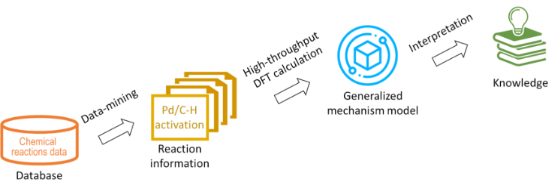
- mild conditions [13]. In particular, reactions involving palladium-catalysed activation of sp2 or sp3 C–H bonds of arenes or alkanes have been extensively investigated due to their wide scope and functional group tolerance [14]. A number of different mechanisms are proposed in the literature

Graphical Abstract

Figure 1: An approximate energy map for the electrophilic aromatic substitution mechanism.

Scheme 1: Schematic representation of the two mechanisms of Pd-catalysed C–H activation reaction considered i...
An overview on disulfide-catalyzed and -cocatalyzed photoreactions
- Yeersen Patehebieke
Beilstein J. Org. Chem. 2020, 16, 1418–1435, doi:10.3762/bjoc.16.118

- alkanes provided an efficient protocol for the synthesis of alkanes from carboxylic acid substrates previously inaccessible through other methods. The mechanism of this reaction is similar to the previously proposed mechanism in Scheme 19. Isomerization reactions Thiyl radical-mediated isomerizations of C

Graphical Abstract

Scheme 1: [3 + 2] cyclization catalyzed by diaryl disulfide.

Scheme 2: [3 + 2] cycloaddition catalyzed by disulfide.

Scheme 3: Disulfide-bridged peptide-catalyzed enantioselective cycloaddition.

Scheme 4: Disulfide-catalyzed [3 + 2] methylenecyclopentane annulations.

Scheme 5: Disulfide as a HAT cocatalyst in the [4 + 2] cycloaddition reaction.

Scheme 6: Proposed mechanism of the [4 + 2] cycloaddition reaction using disulfide as a HAT cocatalyst.

Scheme 7: Disulfide-catalyzed ring expansion of vinyl spiro epoxides.

Scheme 8: Disulfide-catalyzed aerobic oxidation of diarylacetylene.

Scheme 9: Disulfide-catalyzed aerobic photooxidative cleavage of olefins.

Scheme 10: Disulfide-catalyzed aerobic oxidation of 1,3-dicarbonyl compounds.

Scheme 11: Proposed mechanism of the disulfide-catalyzed aerobic oxidation of 1,3-dicarbonyl compounds.

Scheme 12: Disulfide-catalyzed oxidation of allyl alcohols.

Scheme 13: Disulfide-catalyzed diboration of alkynes.

Scheme 14: Dehalogenative radical cyclization catalyzed by disulfide.

Scheme 15: Hydrodifluoroacetamidation of alkenes catalyzed by disulfide.

Scheme 16: Plausible mechanism of the hydrodifluoroacetamidation of alkenes catalyzed by disulfide.

Scheme 17: Disulfide-cocatalyzed anti-Markovnikov olefin hydration reactions.

Scheme 18: Disulfide-catalyzed decarboxylation of carboxylic acids.

Scheme 19: Proposed mechanism of the disulfide-catalyzed decarboxylation of carboxylic acids.

Scheme 20: Disulfide-catalyzed decarboxylation of carboxylic acids.

Scheme 21: Disulfide-catalyzed conversion of maleate esters to fumarates and 5H-furanones.

Scheme 22: Disulfide-catalyzed isomerization of difluorotriethylsilylethylene.

Scheme 23: Disulfide-catalyzed isomerization of allyl alcohols to carbonyl compounds.

Scheme 24: Proposed mechanism for the disulfide-catalyzed isomerization of allyl alcohols to carbonyl compound...

Scheme 25: Diphenyl disulfide-catalyzed enantioselective synthesis of ophirin B.

Scheme 26: Disulfide-catalyzed isomerization in the total synthesis of (+)-hitachimycin.

Scheme 27: Disulfide-catalyzed isomerization in the synthesis of (−)-gloeosporone.
Photocatalysis with organic dyes: facile access to reactive intermediates for synthesis
- Stephanie G. E. Amos,
- Marion Garreau,
- Luca Buzzetti and
- Jerome Waser
Beilstein J. Org. Chem. 2020, 16, 1163–1187, doi:10.3762/bjoc.16.103

- hydrogen atom source (PhSH). The reaction allows the direct conversion of carboxylic acids, e.g., 3.1 to the corresponding alkanes, e.g., 3.2. The scope includes carboxylic acids that were previously recalcitrant to other oxidative photocatalytic decarboxylations due to their high oxidation potential

Graphical Abstract

Figure 1: Selected examples of organic dyes. Mes-Acr+: 9-mesityl-10-methylacridinium, DCA: 9,10-dicyanoanthra...

Scheme 1: Activation modes in photocatalysis.

Scheme 2: Main strategies for the formation of C(sp3) radicals used in organophotocatalysis.

Scheme 3: Illustrative example for the photocatalytic oxidative generation of radicals from carboxylic acids:...

Scheme 4: Illustrative example for the photocatalytic reductive generation of C(sp3) radicals from redoxactiv...

Figure 2: Common substrates for the photocatalytic oxidative generation of C(sp3) radicals.

Scheme 5: Illustrative example for the photocatalytic oxidative generation of radicals from dihydropyridines ...

Scheme 6: Illustrative example for the photocatalytic oxidative generation of C(sp3) radicals from trifluorob...

Scheme 7: Illustrative example for the photocatalytic reductive generation of C(sp3) radicals from benzylic h...

Scheme 8: Illustrative example for the photocatalytic generation of C(sp3) radicals via direct HAT: the cross...

Scheme 9: Illustrative example for the photocatalytic generation of C(sp3) radicals via indirect HAT: the deu...

Scheme 10: Selected precursors for the generation of aryl radicals using organophotocatalysis.

Scheme 11: Illustrative example for the photocatalytic reductive generation of aryl radicals from aryl diazoni...

Scheme 12: Illustrative examples for the photocatalytic reductive generation of aryl radicals from haloarenes:...

Scheme 13: Illustrative example for the photocatalytic reductive generation of aryl radicals from aryl halides...

Scheme 14: Illustrative example for the photocatalytic reductive generation of aryl radicals from arylsulfonyl...

Scheme 15: Illustrative example for the reductive photocatalytic generation of aryl radicals from triaryl sulf...

Scheme 16: Main strategies towards acyl radicals used in organophotocatalysis.

Scheme 17: Illustrative example for the decarboxylative photocatalytic generation of acyl radicals from α-keto...

Scheme 18: Illustrative example for the oxidative photocatalytic generation of acyl radicals from acyl silanes...

Scheme 19: Illustrative example for the oxidative photocatalytic generation of carbamoyl radicals from 4-carba...

Scheme 20: Illustrative example of the photocatalytic HAT approach for the generation of acyl radicals from al...

Scheme 21: General reactivity of a) radical cations; b) radical anions; c) the main strategies towards aryl an...

Scheme 22: Illustrative example for the oxidative photocatalytic generation of alkene radical cations from alk...

Scheme 23: Illustrative example for the reductive photocatalytic generation of an alkene radical anion from al...

Figure 3: Structure of C–X radical anions and their neutral derivatives.

Scheme 24: Illustrative example for the photocatalytic reduction of imines and the generation of an α-amino C(...

Scheme 25: Illustrative example for the oxidative photocatalytic generation of aryl radical cations from arene...

Scheme 26: NCR classifications and generation.

Scheme 27: Illustrative example for the photocatalytic reductive generation of iminyl radicals from O-aryl oxi...

Scheme 28: Illustrative example for the photocatalytic oxidative generation of iminyl radicals from α-N-oxy ac...

Scheme 29: Illustrative example for the photocatalytic oxidative generation of iminyl radicals via an N–H bond...

Scheme 30: Illustrative example for the photocatalytic oxidative generation of amidyl radicals from Weinreb am...

Scheme 31: Illustrative example for the photocatalytic reductive generation of amidyl radicals from hydroxylam...

Scheme 32: Illustrative example for the photocatalytic reductive generation of amidyl radicals from N-aminopyr...

Scheme 33: Illustrative example for the photocatalytic oxidative generation of amidyl radicals from α-amido-ox...

Scheme 34: Illustrative example for the photocatalytic oxidative generation of aminium radicals: the N-aryltet...

Scheme 35: Illustrative example for the photocatalytic oxidative generation of nitrogen-centered radical catio...

Scheme 36: Illustrative example for the photocatalytic oxidative generation of nitrogen-centered radical catio...

Scheme 37: Illustrative example for the photocatalytic oxidative generation of hydrazonyl radical from hydrazo...

Scheme 38: Generation of O-radicals.

Scheme 39: Illustrative examples for the photocatalytic generation of O-radicals from N-alkoxypyridinium salts...

Scheme 40: Illustrative examples for the photocatalytic generation of O-radicals from alkyl hydroperoxides: th...

Scheme 41: Illustrative example for the oxidative photocatalytic generation of thiyl radicals from thiols: the...

Scheme 42: Main strategies and reagents for the generation of sulfonyl radicals used in organophotocatalysis.

Scheme 43: Illustrative example for the reductive photocatalytic generation of sulfonyl radicals from arylsulf...

Scheme 44: Illustrative example of a Cl atom abstraction strategy for the photocatalytic generation of sulfamo...

Scheme 45: Illustrative example for the oxidative photocatalytic generation of sulfonyl radicals from sulfinic...

Scheme 46: Illustrative example for the photocatalytic generation of electronically excited triplet states: th...

Scheme 47: Illustrative example for the photocatalytic generation of electronically excited triplet states: th...
Recent advances in Cu-catalyzed C(sp3)–Si and C(sp3)–B bond formation
- Balaram S. Takale,
- Ruchita R. Thakore,
- Elham Etemadi-Davan and
- Bruce H. Lipshutz
Beilstein J. Org. Chem. 2020, 16, 691–737, doi:10.3762/bjoc.16.67

- decade later, Molander et al. made use of the same disilane as a source of the nucleophile for additions to α,β-unsaturated alkenes and alkynes as Michael acceptors bearing sulfones, nitriles, cyano, amido, and carboxyl ester groups to form β-silylated alkanes and alkenes in good to moderate yields [55

Graphical Abstract

Scheme 1: Pharmaceuticals possessing a silicon or boron atom.

Scheme 2: The first Cu-catalyzed C(sp3)–Si bond formation.

Scheme 3: Conversion of benzylic phosphate 6 to the corresponding silane.

Scheme 4: Conversion of alkyl triflates to alkylsilanes.

Scheme 5: Conversion of secondary alkyl triflates to alkylsilanes.

Scheme 6: Conversion of alkyl iodides to alkylsilanes.

Scheme 7: Trapping of intermediate radical through cascade reaction.

Scheme 8: Radical pathway for conversion of alkyl iodides to alkylsilanes.

Scheme 9: Conversion of alkyl ester of N-hydroxyphthalimide to alkylsilanes.

Scheme 10: Conversion of gem-dibromides to bis-silylalkanes.

Scheme 11: Conversion of imines to α-silylated amines (A) and the reaction pathway (B).

Scheme 12: Conversion of N-tosylimines to α-silylated amines.

Scheme 13: Screening of diamine ligands.

Scheme 14: Conversion of N-tert-butylsulfonylimines to α-silylated amines.

Scheme 15: Conversion of aldimines to nonracemic α-silylated amines.

Scheme 16: Conversion of N-tosylimines to α-silylated amines.

Scheme 17: Reaction pathway [A] and conversion of aldehydes to α-silylated alcohols [B].

Scheme 18: Conversion of aldehydes to benzhydryl silyl ethers.

Scheme 19: Conversion of ketones to 1,2-diols (A) and conversion of imines to 1,2-amino alcohols (B).

Scheme 20: Ligand screening (A) and conversion of aldehydes to α-silylated alcohols (B).

Scheme 21: Conversion of aldehydes to α-silylated alcohols.

Scheme 22: 1,4-Additions to α,β-unsaturated ketones.

Scheme 23: 1,4-Additions to unsaturated ketones to give β-silylated derivatives.

Scheme 24: Additions onto α,β-unsaturated lactones to give β-silylated lactones.

Scheme 25: Conversion of α,β-unsaturated to β-silylated lactams.

Scheme 26: Conversion of N-arylacrylamides to silylated oxindoles.

Scheme 27: Conversion of α,β-unsaturated carbonyl compounds to silylated tert-butylperoxides.

Scheme 28: Catalytic cycle for Cu(I) catalyzed α,β-unsaturated compounds.

Scheme 29: Conversion of p-quinone methides to benzylic silanes.

Scheme 30: Conversion of α,β-unsaturated ketimines to regio- and stereocontrolled allylic silanes.

Scheme 31: Conversion of α,β-unsaturated ketimines to enantioenriched allylic silanes.

Scheme 32: Regioselective conversion of dienedioates to allylic silanes.

Scheme 33: Conversion of alkenyl-substituted azaarenes to β-silylated adducts.

Scheme 34: Conversion of conjugated benzoxazoles to enantioenriched β-silylated adducts.

Scheme 35: Conversion of α,β-unsaturated carbonyl indoles to α-silylated N-alkylated indoles.

Scheme 36: Conversion of β-amidoacrylates to α-aminosilanes.

Scheme 37: Conversion of α,β-unsaturated ketones to enantioenriched β-silylated ketones, nitriles, and nitro d...

Scheme 38: Regio-divergent silacarboxylation of allenes.

Scheme 39: Silylation of diazocarbonyl compounds, (A) asymmetric and (B) racemic.

Scheme 40: Enantioselective hydrosilylation of alkenes.

Scheme 41: Conversion of 3-acylindoles to indolino-silanes.

Scheme 42: Proposed mechanism for the silylation of 3-acylindoles.

Scheme 43: Silyation of N-chlorosulfonamides.

Scheme 44: Conversion of acyl silanes to α-silyl alcohols.

Scheme 45: Conversion of N-tosylaziridines to β-silylated N-tosylamines.

Scheme 46: Conversion of N-tosylaziridines to silylated N-tosylamines.

Scheme 47: Conversion of 3,3-disubstituted cyclopropenes to silylated cyclopropanes.

Scheme 48: Conversion of conjugated enynes to 1,3-bis(silyl)propenes.

Scheme 49: Proposed sequence for the Cu-catalyzed borylation of substituted alkenes.

Scheme 50: Cu-catalyzed synthesis of nonracemic allylic boronates.

Scheme 51: Cu–NHC catalyzed synthesis of α-substituted allylboronates.

Scheme 52: Synthesis of α-chiral (γ-alkoxyallyl)boronates.

Scheme 53: Cu-mediated formation of nonracemic cis- or trans- 2-substituted cyclopropylboronates.

Scheme 54: Cu-catalyzed synthesis of γ,γ-gem-difluoroallylboronates.

Scheme 55: Cu-catalyzed hydrofunctionalization of internal alkenes and vinylarenes.

Scheme 56: Cu-catalyzed Markovnikov and anti-Markovnikov borylation of alkenes.

Scheme 57: Cu-catalyzed borylation/ortho-cyanation/Cope rearrangement.

Scheme 58: Borylfluoromethylation of alkenes.

Scheme 59: Cu-catalyzed synthesis of tertiary nonracemic alcohols.

Scheme 60: Synthesis of densely functionalized and synthetically versatile 1,2- or 4,3-borocyanated 1,3-butadi...

Scheme 61: Cu-catalyzed trifunctionalization of allenes.

Scheme 62: Cu-catalyzed selective arylborylation of arenes.

Scheme 63: Asymmetric borylative coupling between styrenes and imines.

Scheme 64: Regio-divergent aminoboration of unactivated terminal alkenes.

Scheme 65: Cu-catalyzed 1,4-borylation of α,β-unsaturated ketones.

Scheme 66: Cu-catalyzed protodeboronation of α,β-unsaturated ketones.

Scheme 67: Cu-catalyzed β-borylation of α,β-unsaturated imines.

Scheme 68: Cu-catalyzed synthesis of β-trifluoroborato carbonyl compounds.

Scheme 69: Asymmetric 1,4-borylation of α,β-unsaturated carbonyl compounds.

Scheme 70: Cu-catalyzed ACB and ACA reactions of α,β-unsaturated 2-acyl-N-methylimidazoles.

Scheme 71: Cu-catalyzed diborylation of aldehydes.

Scheme 72: Umpolung pathway for chiral, nonracemic tertiary alcohol synthesis (top) and proposed mechanism for...

Scheme 73: Cu-catalyzed synthesis of α-hydroxyboronates.

Scheme 74: Cu-catalyzed borylation of ketones.

Scheme 75: Cu-catalyzed borylation of unactivated alkyl halides.

Scheme 76: Cu-catalyzed borylation of allylic difluorides.

Scheme 77: Cu-catalyzed borylation of cyclic and acyclic alkyl halides.

Scheme 78: Cu-catalyzed borylation of unactivated alkyl chlorides and bromides.

Scheme 79: Cu-catalyzed decarboxylative borylation of carboxylic acids.

Scheme 80: Cu-catalyzed borylation of benzylic, allylic, and propargylic alcohols.
Cascade trifluoromethylthiolation and cyclization of N-[(3-aryl)propioloyl]indoles
- Ming-Xi Bi,
- Shuai Liu,
- Yangen Huang,
- Xiu-Hua Xu and
- Feng-Ling Qing
Beilstein J. Org. Chem. 2020, 16, 657–662, doi:10.3762/bjoc.16.62

- the direct incorporation of the SCF3 group into organic compounds [9][10][11][12][13][14][15][16], such as alkynes, alkenes, arenes, and alkanes. Despite these impressive advances, there is a continued strong demand for new methods that enable the efficient synthesis of SCF3-containing compounds

Graphical Abstract

Figure 1: Representative examples of biologically active pyrrolo[1,2-a]indol-3-one derivatives.

Scheme 1: Radical cascade trifluoromethylthiolation and cyclization reactions.

Scheme 2: Cascade bis(trifluoromethylthiolation) and cyclization of N-[(3-aryl)propioloyl]indoles 1. Reaction...

Scheme 3: Cascade trifluoromethylthiolation and cyclization of N-[(3-aryl)propioloyl]indoles 3. Reaction cond...

Scheme 4: Proposed reaction mechanism.
Synthesis, liquid crystalline behaviour and structure–property relationships of 1,3-bis(5-substituted-1,3,4-oxadiazol-2-yl)benzenes
- Afef Mabrouki,
- Malek Fouzai,
- Armand Soldera,
- Abdelkader Kriaa and
- Ahmed Hedhli
Beilstein J. Org. Chem. 2020, 16, 149–158, doi:10.3762/bjoc.16.17

- , which generates a lamellar packing and thus contributes to smectic phase stability [14]. It was reported that even simple n-alkanes containing a fluorocarbon block produces smectic phases [15][16][17][18][19]. Some molecules having only a single aromatic ring and fluorinated tail show smectic phases

Graphical Abstract

Scheme 1: Synthesis of oxadiazole derivatives 2 and 4.

Scheme 2: Tautomeric equilibrium of compound 3.

Figure 1: DSC thermograms of fluorinated compounds 2b, 4a and 4b recorded at 5 °C/mn at heating (down traces)...

Figure 2: Optical texture (×10) of liquid crystal phase for fluorinated compounds, (a): SmA phase observed in...

Figure 3: Typical diffractogram observed for compound 2b at 398 K.

Figure 4: Typical diffractogram observed for compound 4a at 411 K.

Figure 5: Conformer of lowest energy of compounds: 4c, conformation A, (a) front view, (a’) top view, (a”) si...

Figure 6: Vector of dipole moment of compounds 4c, 4b and 2b.

Figure 7: Plot of molecular dipole moments. Orange, fluorocarbon compounds; blue, hydrocarbon compounds; gree...
Analysis of sesquiterpene hydrocarbons in grape berry exocarp (Vitis vinifera L.) using in vivo-labeling and comprehensive two-dimensional gas chromatography–mass spectrometry (GC×GC–MS)
- Philipp P. Könen and
- Matthias Wüst
Beilstein J. Org. Chem. 2019, 15, 1945–1961, doi:10.3762/bjoc.15.190

- ], while [6,6,6-2H3]-(±)-mevalonolactone (d3-MVL) was purchased from C/D/N Isotopes Inc. (Pointe-Claire, Quebec, Canada). Retention indices were calculated using a C7–C30 saturated alkanes standard solution obtained from Sigma-Aldrich (St. Louis, MO, U.S.A.). The analytical standard (+)-valencene (purity
- mass spectra with those of the NIST database (when available), taking into account the match factors and reverse match factors. A series of n-alkanes (C7–C30) were analyzed. The retention times of the measured n-alkanes on the first GC column were used to calculate the retention indices I according to

Graphical Abstract

Figure 1: Contour plot of a HS-SPME–GC×GC–TOF–MS chromatogram (TIC) demonstrating the separation of volatile ...

Figure 2: Sesquiterpene hydrocarbons found in the headspace of Lemberger (Vitis vinifera subsp. vinifera, clo...

Figure 3: Detailed part of the two-dimensional contour plot (Figure 1) to demonstrate the result of a successful feed...

Scheme 1: First steps towards the formation of sesquiterpenes. The (S)-germacradienyl cation can be formed fr...

Scheme 2: Possible biosynthetic pathways of the sesquiterpene hydrocarbons d8-α-copaene, d8-β-copaene, d8-α-c...

Scheme 3: Mechanistic rationale for the generation of the sesquiterpene hydrocarbons δ-cadinene (14), α-copae...

Figure 4: MS spectra of genuine (d0) and deuterium-labeled (d6 and d8) α-cubebene (left panel) after administ...

Scheme 4: Putative formation pathways of the sesquiterpene hydrocarbons α-ylangene (5), β-ylangene (6), β-bou...

Figure 5: MS spectra and expected labeling patterns of A: d0-α-ylangene, B: d8-α-ylangene after administratio...

Figure 6: Expected labeling patterns of deuterium-labeled, aromatic sesquiterpenes after administration of [6...

Figure 7: MS spectra and expected labeling patterns of genuine and deuterium-labeled A: calamenene (isomer) a...

Figure 8: MS spectra and expected labeling patterns of genuine (d0) and deuterium-labeled (d9) β-elemene afte...

Scheme 5: Possible biosynthesis of d9-β-elemene, d9-(+)-valencene and d9-α-guaiene via germacrene A. *An inco...

Scheme 6: Mechanistic rationale for the generation of the sesquiterpene hydrocarbons γ-elemene and selina-3,7...

Figure 9: Mass spectra and associated structural formulas of d0-γ-elemene and d9-γ-elemene after administrati...

Figure 10: MS spectra and expected labeling patterns of genuine (d0) and deuterium-labeled (d9) guaiazulene af...

Scheme 7: Possible synthesis of d9-guaiazulene, d9-δ-elemene, d9-guaia-6,9-diene and d9-δ-selinene via germac...

Scheme 8: Possible biosynthesis of d6-(E)-β-caryophyllene and d5-α-humulene starting from farnesyl pyrophosph...

Figure 11: MS spectra and expected labeling patterns of d0-(E)-β-caryophyllene and d6-(E)-β-caryophyllene afte...
Transient and intermediate carbocations in ruthenium tetroxide oxidation of saturated rings
- Manuel Pedrón,
- Laura Legnani,
- Maria-Assunta Chiacchio,
- Pierluigi Caramella,
- Tomás Tejero and
- Pedro Merino
Beilstein J. Org. Chem. 2019, 15, 1552–1562, doi:10.3762/bjoc.15.158

- carbocation. In the case of pyrrolidines, the carbocation is completely stabilized as an energy minimum in the form of an iminium ion and the reaction takes place in two steps. Keywords: alkanes; carbocations; DFT; oxidations; ruthenium tetroxide; Introduction Ruthenium-catalyzed oxidations [1][2] and, in
- some chemical behavior. Indeed, further theoretical studies on MD simulations would be needed to elucidate the lifetime of the transient carbocation [34][35]. These results demonstrate the one-step-two-stage character [42] of the ruthenium oxidations of alkanes in which H transfer and O–C bond
- analysis). Energy profile for the oxidation of R4 and R5. Relative energies, calculated at the B3LYP-d3bj/Def2TZVP/cpcm=water level of theory, are given in kcal/mol. Optimized (B3LYP-d3bj/Def2SVP/cpcm=water) transition structures for the oxidation of R4 and R5. Oxidation of alkanes with RuO4. Mechanisms

Graphical Abstract

Scheme 1: Oxidation of alkanes with RuO4.

Scheme 2: Mechanisms for RuO4 oxidation of alkanes.

Scheme 3: Oxidation of saturated five-membered (hetero)cyclic compounds.

Scheme 4: Rate-limiting step for the oxidation of cyclopentane (R1), tetrahydrofuran (R2) and tetrahydrothiop...

Figure 1: Optimized (B3LYP-d3bj/Def2SVP/cpcm=MeCN) geometries of transition structures corresponding to the o...

Figure 2: ELF analysis for the oxidation of cyclopentane (R1). Left: evolution of the electron population alo...

Figure 3: ELF analysis for the oxidation of tetrahydrofuran (R2, A) and tetrahydrothiophene (R3, B). Left: ev...

Figure 4: ELF assignment of electrons to the Ru environment. C(Ru) corresponds to a monosynaptic core basin a...

Scheme 5: Rate-limiting step for the oxidation of N-methyl- and N-benzylpyrrolidines R4 and R5, respectively.

Figure 5: Energy profile for the oxidation of R4 and R5. Relative energies, calculated at the B3LYP-d3bj/Def2...

Figure 6: Optimized (B3LYP-d3bj/Def2SVP/cpcm=water) transition structures for the oxidation of R4 and R5.
Formation of an unexpected 3,3-diphenyl-3H-indazole through a facile intramolecular [2 + 3] cycloaddition of the diazo intermediate
- Andrew T. King,
- Hugh G. Hiscocks,
- Lidia Matesic,
- Mohan Bhadbhade,
- Roger Bishop and
- Alison T. Ung
Beilstein J. Org. Chem. 2019, 15, 1347–1354, doi:10.3762/bjoc.15.134

- structures stabilised by multiple tert-butyl groups [20][21], multi-ring cage hydrocarbons [22][23], and linear alkanes [22][23]. The interaction was found to be attractive in all these cases, and computational justifications have been published [21][23]. It, therefore, appears probable that, despite their

Graphical Abstract

Figure 1: Examples of 18F-radiolabelled arylsulfonyl fluorides containing electron-donating 1, electron-withd...

Scheme 1: Reaction for the formation of sulfonyl chloride 6 using DABSO.

Figure 2: Possible compounds with the molecular formula C33H26N2O (structure 7 contains 27 hydrogen atoms).

Figure 3: ORTEP view of the molecule 8 showing the atom labelling (ellipsoids are drawn at 50% probability le...

Figure 4: Significant intermolecular interactions made by the benzhydryl group (a, upper) and the gem-dipheny...

Figure 5: Relationship of the C–H···N and cyclic C–H···H-C contacts in the crystal structure of 8. The centro...

Figure 6: Part of a hydrocarbon tape along a formed by a combination of alternating linear and cyclic C–H···H...

Scheme 2: Proposed mechanism for the formation of 8.

Scheme 3: Direct preparation of compound 8. method a: t-BuONO, CuCl2, dry CH3CN, −10 °C, 89%; method b: NaNO2...
Mechanochemistry of supramolecules
- Anima Bose and
- Prasenjit Mal
Beilstein J. Org. Chem. 2019, 15, 881–900, doi:10.3762/bjoc.15.86

- capsule 40 formed through hydrogen-bonding and the cavity was found to be able to encapsulate different organic molecules such as alkanes, acids, amines, etc. The encapsulation of a [2.2]paracyclophane in the cage was achieved by ball milling at 30 Hz (Figure 22) and the host–guest product 40 was verified

Graphical Abstract

Figure 1: A generalized overview of coordination-driven self-assembly.

Figure 2: Examples of self-assembly or self-sorting and subsequent substitution.

Figure 3: Synthesis of salen-type ligand followed by metal-complex formation in the same pot [55].

Figure 4: Otera’s solvent-free approach by which the formation of self-assembled supramolecules could be acce...

Figure 5: Synthesis of a Pd-based metalla-supramolecular assembly through mechanochemical activation for C–H-...

Figure 6: a) Schematic representation for the construction of a [2]rotaxane. b) Chiu’s ball-milling approach ...

Figure 7: Mechanochemical synthesis of the smallest [2]rotaxane.

Figure 8: Solvent-free mechanochemical synthesis of pillar[5]arene-containing [2]rotaxanes [61].

Figure 9: Mechanochemical liquid-assisted one-pot two-step synthesis of [2]rotaxanes under high-speed vibrati...

Figure 10: Mechanochemical (ball-milling) synthesis of molecular sphere-like nanostructures [63].

Figure 11: High-speed vibration milling (HSVM) synthesis of boronic ester cages of type 22 [64].

Figure 12: Mechanochemical synthesis of borasiloxane-based macrocycles.

Figure 13: Mechanochemical synthesis of 2-dimensional aromatic polyamides.

Figure 14: Nitschke’s tetrahedral Fe(II) cage 25.

Figure 15: Mechanochemical one-pot synthesis of the 22-component [Fe4(AD2)6]4− 26, 11-component [Fe2(BD2)3]2− ...

Figure 16: a) Subcomponent synthesis of catalyst and reagent and b) followed by multicomponent reaction for sy...

Figure 17: A dynamic combinatorial library (DCL) could be self-sorted to two distinct products.

Figure 18: Mechanochemical synthesis of dynamic covalent systems via thermodynamic control.

Figure 19: Preferential formation of hexamer 33 under mechanochemical shaking via non-covalent interactions of...

Figure 20: Anion templated mechanochemical synthesis of macrocycles cycHC[n] by validating the concept of dyna...

Figure 21: Hydrogen-bond-assisted [2 + 2]-cycloaddition reaction through solid-state grinding. Hydrogen-bond d...

Figure 22: Formation of the cage and encapsulation of [2.2]paracyclophane guest molecule in the cage was done ...

Figure 23: Formation of the 1:1 complex C60–tert-butylcalix[4]azulene through mortar and pestle grinding of th...

Figure 24: Formation of a 2:2 complex between the supramolecular catalyst and the reagent in the transition st...

Figure 25: Halogen-bonded co-crystals via a) I···P, b) I···As, and c) I···Sb bonds [112].

Figure 26: Transformation of contact-explosive primary amines and iodine(III) into a successful chemical react...

Figure 27: Undirected C–H functionalization by using the acidic hydrogen to control basicity of the amines [114]. a...