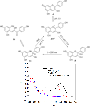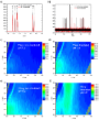

Search for "network" in Full Text gives 336 result(s) in Beilstein Journal of Organic Chemistry. Showing first 200.
Beilstein J. Org. Chem. 2021, 17, 2067–2076, doi:10.3762/bjoc.17.133
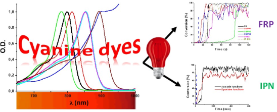
Graphical Abstract
Scheme 1: Investigated NIR dyes.
Scheme 2: Other used chemicals.
Scheme 3: Synthetic routes to compounds Ca, Cb, and CNa.
Scheme 4: Synthetic routes to CI1, CI3, CI4, and CI6–CI9.
Scheme 5: The metathesis reaction enabling the formation of “soft” salts CBPh1-CBPh4.
Figure 1: Visible–NIR spectra of NIR dyes in ACN. A) (1) CBPh1, (2) CBPh2, (3) CBPh3, (4) CBPh4, (5) Ca, (6) ...
Figure 2: Photopolymerization profiles of PETIA monomer under air (acrylate functions conversion vs irradiati...
Figure 3: Photopolymerization profiles of PETIA monomer under air (acrylate functions conversion vs irradiati...
Scheme 6: Pictures of polymers obtained for a thickness of 1.4 mm, using a NIR dye/iod/amine 0.1:3:2, %w/w/w ...
Scheme 7: Proposed mechanism for the photochemical reactivity of NIR dyes in a three-component PIS.
Figure 4: A) Photopolymerization profiles of PETIA/epoxy blend 1:1, w/w under air (acrylate and epoxy functio...
Beilstein J. Org. Chem. 2021, 17, 1981–2025, doi:10.3762/bjoc.17.129

Graphical Abstract
Figure 1: Overview of the methods available for the synthesis of polysaccharides. For each method, advantages...
Figure 2: Overview of the classes of polysaccharides discussed in this review. Each section deals with polysa...
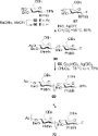
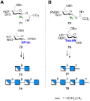
Scheme 1: Enzymatic and chemical polymerization approaches provide cellulose oligomers with a non-uniform dis...
Scheme 2: AGA of a collection of cellulose analogues obtained using BBs 6–9. Specifically placed modification...
Figure 3: Chemical structure of the different branches G, X, L, F commonly found in XGs. Names are given foll...
Scheme 3: AGA of XG analogues with defined side chains. The AGA cycle includes coupling (TMSOTf), Fmoc deprot...
Figure 4: Synthetic strategies and issues associated to the formation of the β(1–3) linkage.
Scheme 4: Convergent synthesis of β(1–3)-glucans using a regioselective glycosylation strategy.
Scheme 5: DMF-mediated 1,2-cis glycosylation. A) General mechanism and B) examples of α-glucans prepared usin...
Scheme 6: Synergistic glycosylation strategy employing a nucleophilic modulation strategy (TMSI and Ph3PO) in...
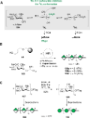
Scheme 7: Different approaches to produce xylans. A) Polymerization techniques including ROP, and B) enzymati...
Scheme 8: A) Synthesis of arabinofuranosyl-decorated xylan oligosaccharides using AGA. Representative compoun...
Scheme 9: Chemoenzymatic synthesis of COS utilizing a lysozyme-catalyzed transglycosylation reaction followed...
Scheme 10: Synthesis of COS using an orthogonal glycosylation strategy based on the use of two different LGs.
Scheme 11: Orthogonal N-PGs permitted the synthesis of COS with different PA.
Scheme 12: AGA of well-defined COS with different PA using two orthogonally protected BBs. The AGA cycle inclu...
Scheme 13: A) AGA of β(1–6)-N-acetylglucosamine hexasaccharide and dodecasaccharide. AGA includes cycles of co...
Figure 5: ‘Double-faced’ chemistry exemplified for ᴅ-Man and ʟ-Rha. Constructing β-Man linkages is considerab...
Figure 6: Implementation of a capping step after each glycosylation cycle for the AGA of a 50mer oligomannosi...
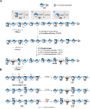
Scheme 14: AGA enabled the synthesis of a linear α(1–6)-mannoside 100mer 93 within 188 h and with an average s...
Scheme 15: The 151mer branched polymannoside was synthesized by a [30 + 30 + 30 + 30 + 31] fragment coupling. ...
Figure 7: PG stereocontrol strategy to obtain β-mannosides. A) The mechanism of the β-mannosylation reaction ...
Scheme 16: A) Mechanism of 1,2-cis stereoselective glycosylation using ManA donors. Once the ManA donor is act...
Figure 8: A) The preferred 4H3 conformation of the gulosyl oxocarbenium ion favors the attack of the alcohol ...
Scheme 17: AGA of type I rhamnans up to 16mer using disaccharide BB 115 and CNPiv PG. The AGA cycle includes c...
Figure 9: Key BBs for the synthesis of the O-antigen of Bacteroides vulgatus up to a 128mer (A) and the CPS o...
Figure 10: Examples of type I and type II galactans synthesized to date.
Figure 11: A) The DTBS PG stabilizes the 3H4 conformation of the Gal oxocarbenium ion favoring the attack of t...
Figure 12: Homogalacturonan oligosaccharides synthesized to date. Access to different patterns of methyl-ester...
Figure 13: GlfT2 from Mycobacterium tuberculosis catalyzes the sequential addition of UPD-Galf donor to a grow...
Figure 14: The poor reactivity of acceptor 137 hindered a stepwise synthesis of the linear galactan backbone a...
Scheme 18: AGA of a linear β(1–5) and β(1–6)-linked galactan 20mer. The AGA cycle includes coupling (NIS/TfOH)...
Figure 15: The 92mer arabinogalactan was synthesized using a [31 + 31 + 30] fragment coupling between a 31mer ...
Scheme 19: Synthesis of the branched arabinofuranose fragment using a six component one-pot synthesis. i) TTBP...
Figure 16: A) Chemical structure and SNFG of the representative disaccharide units forming the GAG backbones, ...
Figure 17: Synthetic challenges associated to the H/HS synthesis.
Scheme 20: Degradation of natural heparin and heparosan generated valuable disaccharides 150 and 151 that can ...
Scheme 21: A) The one-step conversion of cyanohydrin 156 to ʟ-iduronamide 157 represent the key step for the s...
Scheme 22: A) Chemoenzymatic synthesis of heparin structures, using different types of UDP activated natural a...
Scheme 23: Synthesis of the longest synthetic CS chain 181 (24mer) using donor 179 and acceptor 180 in an iter...
Scheme 24: AGA of a collection of HA with different lengths. The AGA cycle includes coupling (TfOH) and Lev de...
Beilstein J. Org. Chem. 2021, 17, 1712–1724, doi:10.3762/bjoc.17.119
Graphical Abstract
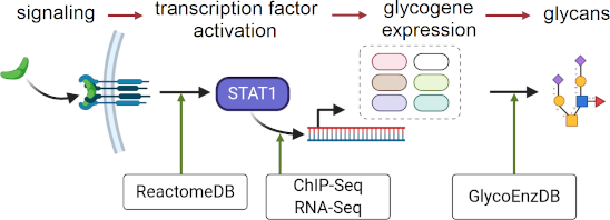
Figure 1: A systems glycobiology framework to link multi-OMICs data. a) Cell signaling proceeds to trigger TF...
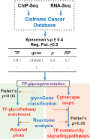
Figure 2: Analysis workflow: ChiP-Seq provides evidence of TF binding to promoter regions with 0 ≤ RP ≤ 1, qu...
Figure 3: Summary of TFs enriched to glycosylation pathways for luminal and basal breast cancer: The TFs foun...
Figure 4: Luminal breast cancer signaling pathway enrichment and glycogene connections. a) TF-to-glycogene co...
Figure 5: Basal breast cancer signaling pathway enrichments and glycogene connections. a) TF-to-glycogene com...
Figure 6: Summary of TF–glycopathway enrichments across all cancer types: TF enrichments to glycopathways acr...
Beilstein J. Org. Chem. 2021, 17, 1689–1697, doi:10.3762/bjoc.17.117
Graphical Abstract
Scheme 1: Mechanism for the phosphine-initiated oxa-Michael addition.
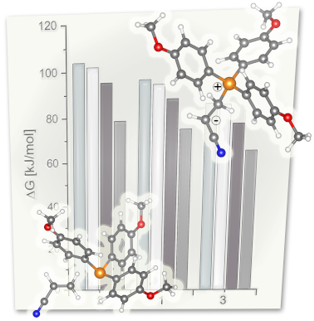
Figure 1: Above: Michael acceptors, Michael donors and catalysts used in this study; pKa (respectively pKa of...
Figure 2: Left: double-bond conversion of the polymerization of 4 initiated by 5 mol % TPP, MMTPP or TMTPP af...
Figure 3: Left: Oxidation stability of the phosphines. Phosphine oxide content in % as determined by 31P NMR ...
Beilstein J. Org. Chem. 2021, 17, 1323–1334, doi:10.3762/bjoc.17.92
Graphical Abstract
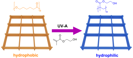
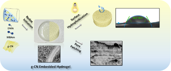
Scheme 1: Schematic overview of g-CN-embedded hydrogel fabrication and its subsequent photoinduced post-modif...
Scheme 2: Hydrophobic hydrogel via photoinduced surface modification over embedded g-CN nanosheets in hydroge...
Figure 1: a) FTIR spectra of freeze-dried HGCM-vTA, HGCM and HG. b) UV spectra of freeze-dried HGCM-vTA, HGCM...
Figure 2: Scanning electron microscopy (SEM) images of a) HGCM and b) HGCM-vTA in combination with their elem...
Figure 3: a) Equilibrium swelling ratios of HG, HGCM, HGCM-vTA at specified time intervals. b) Thermogravimet...
Scheme 3: Overview of pore substructuring via photoinduced free radical polymerization over embedded g-CN nan...
Figure 4: FTIR spectra of freeze-dried HGCM-PAA, HGCM-PAAM, HGCM-PEGMEMA in comparison with HGCM.
Figure 5: Scanning electron microscopy (SEM) images of a) HGCM-PAA, b) HGCM-PAAM, and c) HGCM-PEGMEMA.
Figure 6: a) Thermogravimetric analysis of HGCM, HGCM-PAA, HGCM-PAAM and HGCM-PEGMEMA. b) Equilibrium swellin...
Beilstein J. Org. Chem. 2021, 17, 1181–1312, doi:10.3762/bjoc.17.90
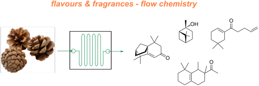
Graphical Abstract
Figure 1: Representative shares of the global F&F market (2018) segmented on their applications [1].
Figure 2: General structure of an international fragrance company [2].
Figure 3: The Michael Edwards fragrance wheel.
Figure 4: Examples of oriental (1–3), woody (4–7), fresh (8–10), and floral (11 and 12) notes.
Figure 5: A basic depiction of batch vs flow.
Scheme 1: Examples of reactions for which flow processing outperforms batch.
Scheme 2: Some industrially important aldol-based transformations.
Scheme 3: Biphasic continuous aldol reactions of acetone and various aldehydes.
Scheme 4: Aldol synthesis of 43 in flow using LiHMDS as the base.
Scheme 5: A semi-continuous synthesis of doravirine (49) involving a key aldol reaction.
Scheme 6: Enantioselective aldol reaction using 5-(pyrrolidin-2-yl)tetrazole (51) as catalyst in a microreact...
Scheme 7: Gröger's example of asymmetric aldol reaction in aqueous media.
Figure 6: Immobilised reagent column reactor types.
Scheme 8: Photoinduced thiol–ene coupling preparation of silica-supported 5-(pyrrolidin-2-yl)tetrazole 63 and...
Scheme 9: Continuous-flow approach for enantioselective aldol reactions using the supported catalyst 67.
Scheme 10: Ötvös’ employment of a solid-supported peptide aldol catalyst in flow.
Scheme 11: The use of proline tetrazole packed in a column for aldol reaction between cyclohexanone (65) and 2...
Scheme 12: Schematic diagram of an aminosilane-grafted Si-Zr-Ti/PAI-HF reactor for continuous-flow aldol and n...
Scheme 13: Continuous-flow condensation for the synthesis of the intermediate 76 to nabumetone (77) and Microi...
Scheme 14: Synthesis of ψ-Ionone (80) in continuous-flow via aldol condensation between citral (79) and aceton...
Scheme 15: Synthesis of β-methyl-ionones (83) from citral (79) in flow. The steps are separately described, an...
Scheme 16: Continuous-flow synthesis of 85 from 84 described by Gavriilidis et al.
Scheme 17: Continuous-flow scCO2 apparatus for the synthesis of 2-methylpentanal (87) and the self-condensed u...
Scheme 18: Chen’s two-step flow synthesis of coumarin (90).
Scheme 19: Pechmann condensation for the synthesis of 7-hydroxyxcoumarin (93) in flow. The setup extended to c...
Scheme 20: Synthesis of the dihydrojasmonate 35 exploiting nitro derivative proposed by Ballini et al.
Scheme 21: Silica-supported amines as heterogeneous catalyst for nitroaldol condensation in flow.
Scheme 22: Flow apparatus for the nitroaldol condensation of p-hydroxybenzaldehyde (102) to nitrostyrene 103 a...
Scheme 23: Nitroaldol reaction of 64 to 105 employing a quaternary ammonium functionalised PANF.
Scheme 24: Enantioselective nitroaldol condensation for the synthesis of 108 under flow conditions.
Scheme 25: Enatioselective synthesis of 1,2-aminoalcohol 110 via a copper-catalysed nitroaldol condensation.
Scheme 26: Examples of Knoevenagel condensations applied for fragrance components.
Scheme 27: Flow apparatus for Knoevenagel condensation described in 1989 by Venturello et al.
Scheme 28: Knoevenagel reaction using a coated multichannel membrane microreactor.
Scheme 29: Continuous-flow apparatus for Knoevenagel condensation employing sugar cane bagasse as support deve...
Scheme 30: Knoevenagel reaction for the synthesis of 131–135 in flow using an amine-functionalised silica gel. ...
Scheme 31: Continuous-flow synthesis of compound 137, a key intermediate for the synthesis of pregabalin (138)...
Scheme 32: Continuous solvent-free apparatus applied for the synthesis of compounds 140–143 using a TSE. Throu...
Scheme 33: Lewis et al. developed a spinning disc reactor for Darzens condensation of 144 and a ketone to furn...
Scheme 34: Some key industrial applications of conjugate additions in the F&F industry.
Scheme 35: Continuous-flow synthesis of 4-(2-hydroxyethyl)thiomorpholine 1,1-dioxide (156) via double conjugat...
Scheme 36: Continuous-flow system for Michael addition using CsF on alumina as the catalyst.
Scheme 37: Calcium chloride-catalysed asymmetric Michael addition using an immobilised chiral ligand.
Scheme 38: Continuous multistep synthesis for the preparation of (R)-rolipram (173). Si-NH2: primary amine-fun...
Scheme 39: Continuous-flow Michael addition using ion exchange resin Amberlyst® A26.
Scheme 40: Preparation of the heterogeneous catalyst 181 developed by Paixão et al. exploiting Ugi multicompon...
Scheme 41: Continuous-flow system developed by the Paixão’s group for the preparation of Michael asymmetric ad...
Scheme 42: Continuous-flow synthesis of nitroaldols catalysed by supported catalyst 184 developed by Wennemers...
Scheme 43: Heterogenous polystyrene-supported catalysts developed by Pericàs and co-workers.
Scheme 44: PANF-supported pyrrolidine catalyst for the conjugate addition of cyclohexanone (65) and trans-β-ni...
Scheme 45: Synthesis of (−)-paroxetine precursor 195 developed by Ötvös, Pericàs, and Kappe.
Scheme 46: Continuous-flow approach for the 5-step synthesis of (−)-oseltamivir (201) as devised by Hayashi an...
Scheme 47: Continuous-flow enzyme-catalysed Michael addition.
Scheme 48: Continuous-flow copper-catalysed 1,4 conjugate addition of Grignard reagents to enones. Reprinted w...
Scheme 49: A collection of commonly encountered hydrogenation reactions.
Figure 7: The ThalesNano H-Cube® continuous-flow hydrogenator.
Scheme 50: Chemoselective reduction of an α,β-unsaturated ketone using the H-Cube® reactor.
Scheme 51: Incorporation of Lindlar’s catalyst into the H-Cube® reactor for the reduction of an alkyne.
Scheme 52: Continuous-flow semi-hydrogenation of alkyne 208 to 209 using SACs with H-Cube® system.
Figure 8: The standard setups for tube-in-tube gas–liquid reactor units.
Scheme 53: Homogeneous hydrogenation of olefins using a tube-in-tube reactor setup.
Scheme 54: Recyclable heterogeneous flow hydrogenation system.
Scheme 55: Leadbeater’s reverse tube-in-tube hydrogenation system for olefin reductions.
Scheme 56: a) Hydrogenation using a Pd-immobilised microchannel reactor (MCR) and b) a representation of the i...
Scheme 57: Hydrogenation of alkyne 238 exploiting segmented flow in a Pd-immobilised capillary reactor.
Scheme 58: Continuous hydrogenation system for the preparation of cyrene (241) from (−)-levoglucosenone (240).
Scheme 59: Continuous hydrogenation system based on CSMs developed by Hornung et al.
Scheme 60: Chemoselective reduction of carbonyls (ketones over aldehydes) in flow.
Scheme 61: Continuous system for the semi-hydrogenation of 256 and 258, developed by Galarneau et al.
Scheme 62: Continuous synthesis of biodiesel fuel 261 from lignin-derived furfural acetone (260).
Scheme 63: Continuous synthesis of γ-valerolacetone (263) via CTH developed by Pineda et al.
Scheme 64: Continuous hydrogenation of lignin-derived biomass (products 265, 266, and 267) using a sustainable...
Scheme 65: Ru/C or Rh/C-catalysed hydrogenation of arene in flow as developed by Sajiki et al.
Scheme 66: Polysilane-immobilized Rh–Pt-catalysed hydrogenation of arenes in flow by Kobayashi et al.
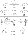
Scheme 67: High-pressure in-line mixing of H2 for the asymmetric reduction of 278 at pilot scale with a 73 L p...
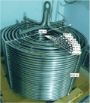
Figure 9: Picture of the PFR employed at Eli Lilly & Co. for the continuous hydrogenation of 278 [287]. Reprinted ...
Scheme 68: Continuous-flow asymmetric hydrogenation using Oppolzer's sultam 280 as chiral auxiliary.
Scheme 69: Some examples of industrially important oxidation reactions in the F&F industry. CFL: compact fluor...
Scheme 70: Gold-catalysed heterogeneous oxidation of alcohols in flow.
Scheme 71: Uozumi’s ARP-Pt flow oxidation protocol.
Scheme 72: High-throughput screening of aldehyde oxidation in flow using an in-line GC.
Scheme 73: Permanganate-mediated Nef oxidation of nitroalkanes in flow with the use of in-line sonication to p...
Scheme 74: Continuous-flow aerobic anti-Markovnikov Wacker oxidation.
Scheme 75: Continuous-flow oxidation of 2-benzylpyridine (312) using air as the oxidant.
Scheme 76: Continuous-flow photo-oxygenation of monoterpenes.
Scheme 77: A tubular reactor design for flow photo-oxygenation.
Scheme 78: Glucose oxidase (GOx)-mediated continuous oxidation of glucose using compressed air and the FFMR re...
Scheme 79: Schematic continuous-flow sodium hypochlorite/TEMPO oxidation of alcohols.
Scheme 80: Oxidation using immobilised TEMPO (344) was developed by McQuade et al.
Scheme 81: General protocol for the bleach/catalytic TBAB oxidation of aldehydes and alcohols.
Scheme 82: Continuous-flow PTC-assisted oxidation using hydrogen peroxide. The process was easily scaled up by...
Scheme 83: Continuous-flow epoxidation of cyclohexene (348) and in situ preparation of m-CPBA.
Scheme 84: Continuous-flow epoxidation using DMDO as oxidant.
Scheme 85: Mukayama aerobic epoxidation optimised in flow mode by the Favre-Réguillon group.
Scheme 86: Continuous-flow asymmetric epoxidation of derivatives of 359 exploiting a biomimetic iron catalyst.
Scheme 87: Continuous-flow enzymatic epoxidation of alkenes developed by Watts et al.
Scheme 88: Engineered multichannel microreactor for continuous-flow ozonolysis of 366.
Scheme 89: Continuous-flow synthesis of the vitamin D precursor 368 using multichannel microreactors. MFC: mas...
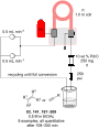
Scheme 90: Continuous ozonolysis setup used by Kappe et al. for the synthesis of various substrates employing ...
Scheme 91: Continuous-flow apparatus for ozonolysis as developed by Ley et al.
Scheme 92: Continuous-flow ozonolysis for synthesis of vanillin (2) using a film-shear flow reactor.
Scheme 93: Examples of preparative methods for ajoene (386) and allicin (388).
Scheme 94: Continuous-flow oxidation of thioanisole (389) using styrene-based polymer-supported peroxytungstat...
Scheme 95: Continuous oxidation of thiosulfinates using Oxone®-packed reactor.
Scheme 96: Continuous-flow electrochemical oxidation of thioethers.
Scheme 97: Continuous-flow oxidation of 400 to cinnamophenone (235).
Scheme 98: Continuous-flow synthesis of dehydrated material 401 via oxidation of methyl dihydrojasmonate (33).
Scheme 99: Some industrially important transformations involving Grignard reagents.
Scheme 100: Grachev et al. apparatus for continuous preparation of Grignard reagents.
Scheme 101: Example of fluidized Mg bed reactor with NMR spectrometer as on-line monitoring system.
Scheme 102: Continuous-flow synthesis of Grignard reagents and subsequent quenching reaction.
Figure 10: Membrane-based, liquid–liquid separator with integrated pressure control [52]. Adapted with permission ...
Scheme 103: Continuous-flow synthesis of 458, an intermediate to fluconazole (459).
Scheme 104: Continuous-flow synthesis of ketones starting from benzoyl chlorides.
Scheme 105: A Grignard alkylation combining CSTR and PFR technologies with in-line infrared reaction monitoring....
Scheme 106: Continuous-flow preparation of 469 from Grignard addition of methylmagnesium bromide.
Scheme 107: Continuous-flow synthesis of Grignard reagents 471.
Scheme 108: Preparation of the Grignard reagent 471 using CSTR and the continuous process for synthesis of the ...
Scheme 109: Continuous process for carboxylation of Grignard reagents in flow using tube-in-tube technology.
Scheme 110: Continuous synthesis of propargylic alcohols via ethynyl-Grignard reagent.
Scheme 111: Silica-supported catalysed enantioselective arylation of aldehydes using Grignard reagents in flow ...
Scheme 112: Acid-catalysed rearrangement of citral and dehydrolinalool derivatives.
Scheme 113: Continuous stilbene isomerisation with continuous recycling of photoredox catalyst.
Scheme 114: Continuous-flow synthesis of compound 494 as developed by Ley et al.
Scheme 115: Selected industrial applications of DA reaction.
Scheme 116: Multistep flow synthesis of the spirocyclic structure 505 via employing DA cycloaddition.
Scheme 117: Continuous-flow DA reaction developed in a plater flow reactor for the preparation of the adduct 508...
Scheme 118: Continuous-flow DA reaction using a silica-supported imidazolidinone organocatalyst.
Scheme 119: Batch vs flow for the DA reaction of (cyclohexa-1,5-dien-1-yloxy)trimethylsilane (513) with acrylon...
Scheme 120: Continuous-flow DA reaction between 510 and 515 using a shell-core droplet system.
Scheme 121: Continuous-flow synthesis of bicyclic systems from benzyne precursors.
Scheme 122: Continuous-flow synthesis of bicyclic scaffolds 527 and 528 for further development of potential ph...
Scheme 123: Continuous-flow inverse-electron hetero-DA reaction to pyridine derivatives such as 531.
Scheme 124: Comparison between batch and flow for the synthesis of pyrimidinones 532–536 via retro-DA reaction ...
Scheme 125: Continuous-flow coupled with ultrasonic system for preparation of ʟ-ascorbic acid derivatives 539 d...
Scheme 126: Two-step continuous-flow synthesis of triazole 543.
Scheme 127: Continuous-flow preparation of triazoles via CuAAC employing 546-based heterogeneous catalyst.
Scheme 128: Continuous-flow synthesis of compounds 558 through A3-coupling and 560 via AgAAC both employing the...
Scheme 129: Continuous-flow photoinduced [2 + 2] cycloaddition for the preparation of bicyclic derivatives of 5...
Scheme 130: Continuous-flow [2 + 2] and [5 + 2] cycloaddition on large scale employing a flow reactor developed...
Scheme 131: Continuous-flow preparation of the tricyclic structures 573 and 574 starting from pyrrole 570 via [...
Scheme 132: Continuous-flow [2 + 2] photocyclization of cinnamates.
Scheme 133: Continuous-flow preparation of cyclobutane 580 on a 5-plates photoreactor.
Scheme 134: Continuous-flow [2 + 2] photocycloaddition under white LED lamp using heterogeneous PCN as photocat...
Figure 11: Picture of the parallel tube flow reactor (PTFR) "The Firefly" developed by Booker-Milburn et al. a...
Scheme 135: Continuous-flow acid-catalysed [2 + 2] cycloaddition between silyl enol ethers and acrylic esters.
Scheme 136: Continuous synthesis of lactam 602 using glass column reactors.
Scheme 137: In situ generation of ketenes for the Staudinger lactam synthesis developed by Ley and Hafner.
Scheme 138: Application of [2 + 2 + 2] cycloadditions in flow employed by Ley et al.
Scheme 139: Examples of FC reactions applied in F&F industry.
Scheme 140: Continuous-flow synthesis of ibuprofen developed by McQuade et al.
Scheme 141: The FC acylation step of Jamison’s three-step ibuprofen synthesis.
Scheme 142: Synthesis of naphthalene derivative 629 via FC acylation in microreactors.
Scheme 143: Flow system for rapid screening of catalysts and reaction conditions developed by Weber et al.
Scheme 144: Continuous-flow system developed by Buorne, Muller et al. for DSD optimisation of the FC acylation ...
Scheme 145: Continuous-flow FC acylation of alkynes to yield β-chlorovinyl ketones such as 638.
Scheme 146: Continuous-flow synthesis of tonalide (619) developed by Wang et al.
Scheme 147: Continuous-flow preparation of acylated arene such as 290 employing Zr4+-β-zeolite developed by Kob...
Scheme 148: Flow system applied on an Aza-FC reaction catalysed by the thiourea catalyst 648.
Scheme 149: Continuous hydroformylation in scCO2.
Scheme 150: Two-step flow synthesis of aldehyde 655 through a sequential Heck reaction and subsequent hydroform...
Scheme 151: Single-droplet (above) and continuous (below) flow reactors developed by Abolhasani et al. for the ...
Scheme 152: Continuous hydroformylation of 1-dodecene (655) using a PFR-CSTR system developed by Sundmacher et ...
Scheme 153: Continuous-flow synthesis of the aldehyde 660 developed by Eli Lilly & Co. [32]. Adapted with permissio...
Scheme 154: Continuous asymmetric hydroformylation employing heterogenous catalst supported on carbon-based sup...
Scheme 155: Examples of acetylation in F&F industry: synthesis of bornyl (S,R,S-664) and isobornyl (S,S,S-664) ...
Scheme 156: Continuous-flow preparation of bornyl acetate (S,R,S-664) employing the oscillating flow reactor.
Scheme 157: Continuous-flow synthesis of geranyl acetate (666) from acetylation of geraniol (343) developed by ...
Scheme 158: 12-Ttungstosilicic acid-supported silica monolith-catalysed acetylation in flow.
Scheme 159: Continuous-flow preparation of cyclopentenone 676.
Scheme 160: Two-stage synthesis of coumarin (90) via acetylation of salicylaldehyde (88).
Scheme 161: Intensification process for acetylation of 5-methoxytryptamine (677) to melatonin (678) developed b...
Scheme 162: Examples of macrocyclic musky odorants both natural (679–681) and synthetic (682 and 683).
Scheme 163: Flow setup combined with microwave for the synthesis of macrocycle 686 via RCM.
Scheme 164: Continuous synthesis of 2,5-dihydro-1H-pyrroles via ring-closing metathesis.
Scheme 165: Continuous-flow metathesis of 485 developed by Leadbeater et al.
Figure 12: Comparison between RCM performed using different routes for the preparation of 696. On the left the...
Scheme 166: Continuous-flow RCM of 697 employed the solid-supported catalyst 698 developed by Grela, Kirschning...
Scheme 167: Continuous-flow RORCM of cyclooctene employing the silica-absorbed catalyst 700.
Scheme 168: Continuous-flow self-metathesis of methyl oleate (703) employing SILP catalyst 704.
Scheme 169: Flow apparatus for the RCM of 697 using a nanofiltration membrane for the recovery and reuse of the...
Scheme 170: Comparison of loadings between RCMs performed with different routes for the synthesis of 709.
Beilstein J. Org. Chem. 2021, 17, 1149–1170, doi:10.3762/bjoc.17.88
Graphical Abstract
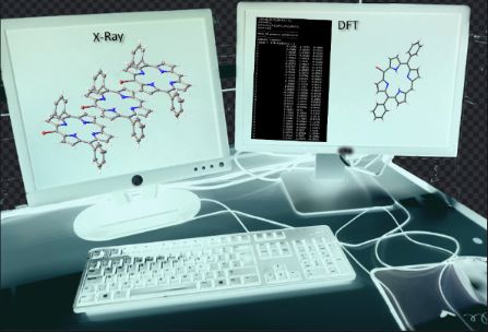
Figure 1: 5-Halo-substituted porphyrins.
Figure 2: Expanded view (thermal ellipsoid) of compound 1 in the crystal showing (A) stacking, (B) tilted edg...
Figure 3: Expanded view (ball and stick) of compound 2 in the crystal showing (A) stacking, (B) bromine atoms...
Figure 4: Expanded view (ball and stick) of compound 3 in the crystal showing (A) stacking and (B) edge-on in...
Figure 5: Hirshfeld surfaces of compounds 1–3.
Figure 6: Contact percentages of compounds 1–3.
Figure 7: NSD charts for compounds 1–3.
Figure 8: Expanded view (thermal ellipsoid plot) of compound 2A showing (A) the edge-on and stacking interact...
Figure 9: 5-Halo-15-phenyl-substituted porphyrins.
Figure 10: Expanded view (thermal ellipsoid plot) of compound 4 showing (A) tilted alignment of porphyrin ring...
Figure 11: Expanded view (thermal ellipsoid plot) of compound 5 showing (A) porphyrin stacking and (B) Br···H ...
Figure 12: Expanded view (thermal ellipsoid plot) of compounds 6 (A and C) and 7 (B and D) showing (A) Br···H ...
Figure 13: 5,15-Di-halo-substituted porphyrins.
Figure 14: Expanded view (thermal ellipsoid plot) of compound 9 showing the Br···H interactions with (A) pyrro...
Figure 15: Expanded view (thermal ellipsoid plot) of compound 10 showing the (A) Br···H interactions with toly...
Figure 16: Expanded view (thermal ellipsoid plot) of compound 11 showing the (A) edge-on interactions, (B) edg...
Figure 17: Expanded view (thermal ellipsoid plot) of compound 13 showing (A) Br···H interactions with pyrrole ...
Figure 18: Expanded view (ball and stick) of compound 13A showing (A) Br···H interactions with pyrrole units a...
Figure 19: 5,10-Di-halo-substituted porphyrins.
Figure 20: Expanded view (ball and stick) of compound 16 showing (A) stacking, (B) head-to-tail alignment, (C)...
Figure 21: Honorable mentions of halogen-substituted porphyrins taken from the CSD database.
Figure 22: Series 1 – 5,15-di-halo-substituted porphyrins.
Figure 23: Series 2 – increasing number of halogen substituents.
Figure 24: Series 3 – 5,10-di-halo-substituted porphyrins.
Beilstein J. Org. Chem. 2021, 17, 1041–1047, doi:10.3762/bjoc.17.83
Graphical Abstract
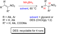
Scheme 1: AB-mediated reductions of nitrostyrenes 3a–h.
Scheme 2: AB-mediated reductions of nitrostyrenes 1, 3a, and 3c using DESs B and D.
Scheme 3: AB-mediated reductions of nitroalkenes 5a–f.
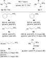
Scheme 4: Recovery and recycling experiments in the AB-mediated reduction of nitrostyrene 3h to afford nitroa...
Beilstein J. Org. Chem. 2021, 17, 866–872, doi:10.3762/bjoc.17.72
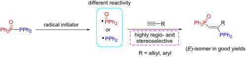
Graphical Abstract
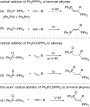
Scheme 1: Radical addition of Ph2PPPh2 and Ph2P(X)PPh2 to unsaturated C–C bonds.
Scheme 2: The addition of Ph2P(O)PPh2 (1) to 1-octyne (2a).
Scheme 3: Phosphinylphosphination of various terminal alkynes 2 with 1. aIsolated yields. V-40 = 1,1’-azobis(...
Scheme 4: Attempted radical addition to internal alkynes and insight into the addition to 2n.
Scheme 5: A plausible reaction pathway for the radical addition of Ph2P(O)PPh2 to terminal alkynes.
Beilstein J. Org. Chem. 2021, 17, 739–748, doi:10.3762/bjoc.17.64
Graphical Abstract
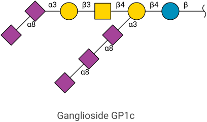
Figure 1: Chemical structure of ganglioside GM1a (a β-ᴅ-galactosyl-(1→3)-N-acetyl-β-ᴅ-galactosaminyl-(1→4)-[α-...
Figure 2: Construction of the Svennerholm name GP1cα from its Glycologue structure identifier. At each step o...
Figure 3: Ganglioside carbohydrates predicted by the model. All structures are linked to ceramide at the base...
Figure 4: Ganglioside biosynthetic reaction network predicted by the Glycologue enzyme simulator. Starting fr...
Figure 5: Predicted effects on the pathways of ganglioside biosynthesis when individual enzyme activities are...
Beilstein J. Org. Chem. 2021, 17, 558–568, doi:10.3762/bjoc.17.50
Graphical Abstract
Figure 1: Structure of biologically active phthalazine derivatives.
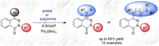
Scheme 1: Synthetic route to aminophthalazinones 5 and 6.
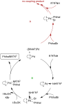
Figure 2: Proposed catalytic cycles for the amination of 4-bromophthalazinones of type 3 (Phthal: phthalazino...
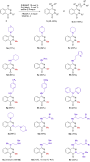
Scheme 2: Synthesis of 4-amino- and 4-polyaminophthalazinones 5 and 6 (the yields refer to the isolated compo...
Figure 3: The phthalazinone derivatives that were used to test the complexation of Cu(II) ions.
Scheme 3: The proposal of the fragmentation pathway of the Cu(II) complex with compound 7.
Figure 4: Structure of complex 17.
Figure 5: Molecular structure of complex 17 with atom numbering scheme. The anisotropic displacement paramete...
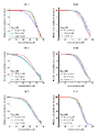
Figure 6: Determination of relative cell viability (% of control) in different cell lines (HT-29; PC-3 and L-...
Figure 7: Cytotoxic properties of the phthalazinone derivatives expressed as IC50 after 72 h of cell treatmen...
Beilstein J. Org. Chem. 2021, 17, 343–378, doi:10.3762/bjoc.17.32
Graphical Abstract
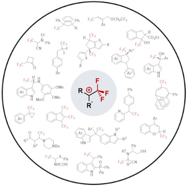
Figure 1: Stabilizing interaction in the CF3CH2+ carbenium ion (top) and structure of the first observable fl...
Scheme 1: Isodesmic equations accounting for the destabilizing effect of the CF3 group. ΔE in kcal⋅mol−1, cal...
Scheme 2: Stabilizing effect of fluorine atoms by resonance electron donation in carbenium ions (δ in ppm).
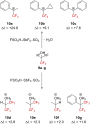
Scheme 3: Direct in situ NMR observation of α-(trifluoromethyl)carbenium ion or protonated alcohols. Δδ = δ19...
Scheme 4: Reported 13C NMR chemical shifts for the α-(trifluoromethyl)carbenium ion 10c (δ in ppm).
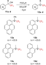
Scheme 5: Direct NMR observation of α-(trifluoromethyl)carbenium ions in situ (δ in ppm).
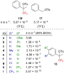
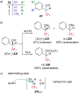
Scheme 6: Illustration of the ion pair solvolysis mechanism for sulfonate 13f. YOH = solvent.
Figure 2: Solvolysis rate for 13a–i and 17.
Figure 3: Structures of allyl triflates 18 and 19 and allyl brosylate 20. Bs = p-BrC6H4SO2.
Figure 4: Structure of tosylate derivatives 21.
Figure 5: a) Structure of triflate derivatives 22. b) Stereochemistry outcomes of the reaction starting from (...
Scheme 7: Solvolysis reaction of naphthalene and anthracenyl derivatives 26 and 29.
Figure 6: Structure of bisarylated derivatives 34.
Figure 7: Structure of bisarylated derivatives 36.
Scheme 8: Reactivity of 9c in the presence of a Brønsted acid.
Scheme 9: Cationic electrocyclization of 38a–c under strongly acidic conditions.
Scheme 10: Brønsted acid-catalyzed synthesis of indenes 42 and indanes 43.
Scheme 11: Reactivity of sulfurane 44 in triflic acid.
Scheme 12: Solvolysis of triflate 45f in alcoholic solvents.
Scheme 13: Synthesis of labeled 18O-52.
Scheme 14: Reactivity of sulfurane 53 in triflic acid.
Figure 8: Structure of tosylates 56 and 21f.
Scheme 15: Resonance forms in benzylic carbenium ions.
Figure 9: Structure of pyrrole derivatives 58 and 59.
Scheme 16: Resonance structure 60↔60’.
Scheme 17: Ga(OTf)3-catalyzed synthesis of 3,3’- and 3,6’-bis(indolyl)methane from trifluoromethylated 3-indol...
Scheme 18: Proposed reaction mechanism.
Scheme 19: Metal-free 1,2-phosphorylation of 3-indolylmethanols.
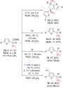
Scheme 20: Superacid-mediated arylation of thiophene derivatives.
Scheme 21: In situ mechanistic NMR investigations.
Scheme 22: Proposed mechanisms for the prenyltransferase-catalyzed condensation.
Scheme 23: Influence of a CF3 group on the allylic SN1- and SN2-mechanism-based reactions.
Scheme 24: Influence of the CF3 group on the condensation reaction.
Scheme 25: Solvolysis of 90 in TFE.
Scheme 26: Solvolysis of allyl triflates 94 and 97 and isomerization attempt of 96.
Scheme 27: Proposed mechanism for the formation of 95.
Scheme 28: Formation of α-(trifluoromethyl)allylcarbenium ion 100 in a superacid.
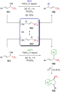
Scheme 29: Lewis acid activation of CF3-substituted allylic alcohols.
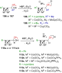
Scheme 30: Bimetallic-cluster-stabilized α-(trifluoromethyl)carbenium ions.
Scheme 31: Reactivity of cluster-stabilized α-(trifluoromethyl)carbenium ions.
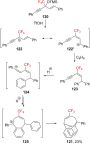
Scheme 32: α-(Trifluoromethyl)propargylium ion 122↔122’ generated from silyl ether 120 in a superacid.
Scheme 33: Formation of α-(trifluoromethyl)propargylium ions from CF3-substituted propargyl alcohols.
Scheme 34: Direct NMR observation of the protonation of some trifluoromethyl ketones in situ and the correspon...
Scheme 35: Selected resonance forms in protonated fluoroketone derivatives.
Scheme 36: Acid-catalyzed Friedel–Crafts reactions of trifluoromethyl ketones 143a,b and 147a–c.
Scheme 37: Enantioselective hydroarylation of CF3-substituted ketones.
Scheme 38: Acid-catalyzed arylation of ketones 152a–c.
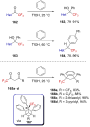
Scheme 39: Reactivity of 156 in a superacid.
Scheme 40: Reactivity of α-CF3-substituted heteroaromatic ketones and alcohols as well as 1,3-diketones.
Scheme 41: Reactivity of 168 with benzene in the presence of a Lewis or Brønsted acid.
Scheme 42: Acid-catalyzed three-component asymmetric reaction.
Scheme 43: Anodic oxidation of amines 178a–c and proposed mechanism.
Scheme 44: Reactivity of 179b in the presence of a strong Lewis acid.
Scheme 45: Trifluoromethylated derivatives as precursors of trifluoromethylated iminium ions.
Scheme 46: Mannich reaction with trifluoromethylated hemiaminal 189.
Scheme 47: Suitable nucleophiles reacting with 192 after Lewis acid activation.
Scheme 48: Strecker reaction involving the trifluoromethylated iminium ion 187.
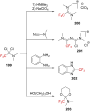
Scheme 49: Reactivity of 199 toward nucleophiles.
Scheme 50: Reactivity of 204a with benzene in the presence of a Lewis acid.
Scheme 51: Reactivity of α-(trifluoromethyl)-α-chloro sulfides in the presence of strong Lewis acids.
Scheme 52: Anodic oxidation of sulfides 213a–h and Pummerer rearrangement.
Scheme 53: Mechanism for the electrochemical oxidation of the sulfide 213a.
Scheme 54: Reactivity of (trifluoromethyl)diazomethane (217a) in HSO3F.
Figure 10: a) Structure of diazoalkanes 217a–c and b) rate-limiting steps of their decomposition.
Scheme 55: Deamination reaction of racemic 221 and enantioenriched (S)-221.
Scheme 56: Deamination reaction of labeled 221-d2. Elimination products were formed in this reaction, the yiel...
Scheme 57: Deamination reaction of 225-d2. Elimination products were also formed in this reaction in undetermi...
Scheme 58: Formation of 229 from 228 via 1,2-H-shift.
Scheme 59: Deamination reaction of 230. Elimination products were formed in this reaction, the yield of which ...
Scheme 60: Deamination of several diazonium ions. Elimination products were formed in these reactions, the yie...
Scheme 61: Solvolysis reaction mechanism of alkyl tosylates.
Scheme 62: Solvolysis outcome for the tosylates 248 and 249 in HSO3FSbF5.
Figure 11: Solvolysis rate of 248, 249, 252, and 253 in 91% H2SO4.
Scheme 63: Illustration of the reaction pathways. TsCl, pyridine, −5 °C (A); 98% H2SO4, 30 °C (B); 98% H2SO4, ...
Scheme 64: Proposed solvolysis mechanism for the aliphatic tosylate 248.
Scheme 65: Solvolysis of the derivatives 259 and 260.
Scheme 66: Solvolysis of triflate 261. SOH = solvent.
Scheme 67: Intramolecular Friedel–Crafts alkylations upon the solvolysis of triflates 264 and 267.
Scheme 68: α-CF3-enhanced γ-silyl elimination of cyclobutyltosylates 270a,b.
Scheme 69: γ-Silyl elimination in the synthesis of a large variety of CF3-substituted cyclopropanes. Pf = pent...
Scheme 70: Synthetic pathways to 281. aNMR yields.
Scheme 71: The cyclopropyl-substituted homoallylcyclobutylcarbenium ion manifold.
Scheme 72: Reactivity of CF3-substituted cyclopropylcarbinyl derivatives 287a–c. LG = leaving group.
Scheme 73: Reactivity of CF3-substituted cyclopropylcarbinyl derivatives 291a–c.
Scheme 74: Superacid-promoted dimerization or TFP.
Scheme 75: Reactivity of TFP in a superacid.
Scheme 76: gem-Difluorination of α-fluoroalkyl styrenes via the formation of a “hidden” α-RF-substituted carbe...
Scheme 77: Solvolysis of CF3-substituted pentyne 307.
Scheme 78: Photochemical rearrangement of 313.
Figure 12: Structure of 2-norbornylcarbenium ion 318 and argued model for the stabilization of this cation.
Figure 13: Structures and solvolysis rate (TFE, 25 °C) of the sulfonates 319–321. Mos = p-MeOC6H4SO2.
Scheme 79: Mechanism for the solvolysis of 323. SOH = solvent.
Scheme 80: Products formed by the hydrolysis of 328.
Scheme 81: Proposed carbenium ion intermediates in an equilibrium during the solvolysis of tosylates 328, 333,...
Beilstein J. Org. Chem. 2021, 17, 166–185, doi:10.3762/bjoc.17.17
Graphical Abstract
Scheme 1: The chemical network of reactions for 4-hydroxyflavylium (left) and the write-lock-erase cycle (rig...
Scheme 2: The building blocks used for the self-assembly in this study: pelargonidin chloride (Flavy), 1-naph...
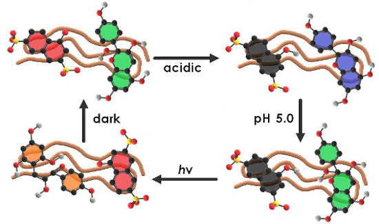
Scheme 3: Overview of the different states of the multi-switchable system consisting of Flavy, 1N36S, and pol...
Figure 1: Top: pelargonidin cation (Flavy) and network of chemical reactions; bottom: corresponding UV–vis sp...
Figure 2: Characterization of Flavy: a) 1H NMR spectrum at pH 7.0 (form A) before and after irradiation; b) 13...
Scheme 4: Overview of the different states of the two main cycles switching the system consisting of 1N36S, F...
Figure 3: UV–vis spectroscopy of the ternary nano-assemblies for cycle I (a) and cycle II (b).
Figure 4: Dynamic light scattering: Electric field autocorrelation function g1(τ) and distribution of relaxat...
Figure 5: Static light scattering data from the assemblies of cycle I; a) A, non-irradiated, spherical partic...
Figure 6: Comparison of cycle I and cycle II in AFM.
Figure 7: a) ζ-Potential and b) effective surface charge density for cycle I; c) ζ-potential and d) effective...
Figure 8: Isothermal titration calorimetry of poly(allylamine) into the cell containing Flavy and 1N36S in aq...
Figure 9: Polar surface area of Flavy in form of A (left) and B (right).
Figure 10: Hydrodynamic radii of the nano-assemblies as function of the loading ratio: a) cycle I, b) cycle II....
Figure 11: UV–vis spectra of the nano-assemblies of cycle II at l = 0.75.
Figure 12: ζ-Potential of the nano-assemblies of cycle II depending on the concentration ratio.
Scheme 5: Different mixing orders of the assemblies. The major part of this study focuses on route i.
Beilstein J. Org. Chem. 2020, 16, 3032–3037, doi:10.3762/bjoc.16.252
Graphical Abstract
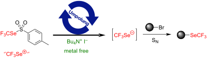
Scheme 1: State of the art concerning the direct nucleophilic trifluoromethylselenolation.
Scheme 2: The nucleophilic fluoroalkylselenolation of alkyl bromides. Yields were determined by 19F NMR spect...
Scheme 3: Mechanism proposal.
Beilstein J. Org. Chem. 2020, 16, 2948–2953, doi:10.3762/bjoc.16.244
Graphical Abstract
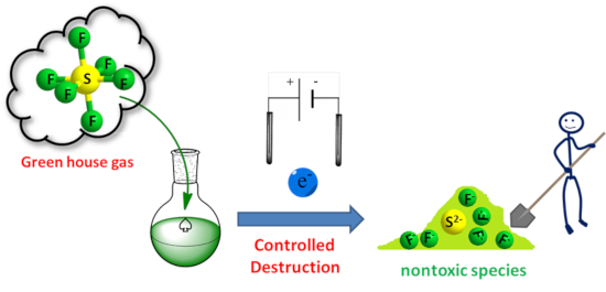
Figure 1: (a) Cyclic voltammetry onto microelectrode arrays (Ø = 20 µm) in acetonitrile freshly distilled aft...
Figure 2: Variation of the current reduction (i2) of SF6 onto Pt macroelectrode (Ø = 0.76 mm) at −2.3 V vs Fc+...
Figure 3: Single compartment three-electrode experiment. 1: Balloon of SF6, 2: electrochemical cell, 3: refer...
Figure 4: Electrolysis of SF6 at −2.3 V vs Fc+/Fc in acetonitrile freshly distilled after addition of TBAClO4...
Figure 5: 19F NMR evolution of the crude mixture along the time after electrolysis realized at constant poten...
Beilstein J. Org. Chem. 2020, 16, 2831–2853, doi:10.3762/bjoc.16.233
Graphical Abstract
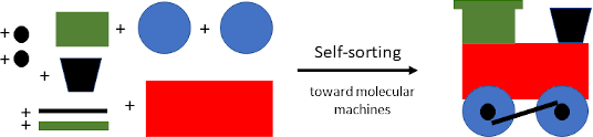
Figure 1: Some selected self-sorting outcomes and their qualitative and quantitative assessment.
Figure 2: Illustration of an integrative vs a non-integrative self-sorting.
Figure 3: The pH-driven four-component 2-fold completive self-sorting based on host–guest chemistry.
Figure 4: (a) The monomers 5 and 6 and their H-bonding array. (b) The hydrogen-bonded octameric and tetrameri...
Figure 5: (a) Two new Zn4L6-type cages. (b) The encapsulation of C70 induced distinct reconstitutions within ...
Figure 6: The formation of octahedral cages (a) [Co6(10')4]12+ and (b) [Co6(11')4]12+. (c) The 2-fold complet...
Figure 7: Exchange of Ag+ for Au+ ions in poly-NHC ligand-based organometallic assemblies.
Figure 8: The reversible interconversion between the three-component rectangle [Cu4(16)2(17)2]4+ and the four...
Figure 9: a) Chemical structure of the monomer 20 with its quadruple hydrogen-bonding array and a metal-affin...
Figure 10: Communication between the nanoswitch 21 and the supramolecular assemblies [Cu4(22)2(24)2]4+ or [Cu6(...
Figure 11: (a) The chemical structures and cartoon representations of the switch 25, the decks 26 and 27, and ...
Figure 12: Double self-sorting leads to a catalytic machinery in SelfSORT-II, in which the 46 kHz-nanorotor ac...
Figure 13: ON/OFF control of a networked catalytic catch–release system.
Figure 14: A multicomponent information system for the reversible reconfiguration of switchable dual catalysis....
Figure 15: a) The chemically fueled cascaded ion translocation, monitored by distinct emission colors. b) Work...
Figure 16: Cyclic metallosupramolecular transformations.
Figure 17: Fully reversible multiple-state rearrangement of metallosupramolecular architectures depending upon...
Figure 18: The selective encapsulation and sequential release of guests in a self-sorted mixture of three tetr...
Figure 19: Two catalytic reactions are alternately controlled by a toggle nanoswitch.
Figure 20: A biped walking along a tetrahedral track and unfolding its catalytic action. Adapted with permissi...
Figure 21: A three state supramolecular AND logic gate.
Figure 22: Four-component nanorotor and its catalytic activity. Adapted with permission from (Biswas, P. K.; S...
Beilstein J. Org. Chem. 2020, 16, 2820–2830, doi:10.3762/bjoc.16.232
Graphical Abstract
Figure 1: Chemical structure of dirhamnolipid 1.
Scheme 1: Synthesis of the dirhamnolipid esters and the chemical structure of 7.
Figure 2: Solubility of the dirhamnolipid esters in various solvents (+ = soluble, − = insoluble, G = gel).
Figure 3: Phase transition temperature for the dirhamnolipid esters in toluene while heating (TGS, blue) and ...
Figure 4: Amplitude sweep: double logarithmic plot of the dynamic moduli against the amplitude (deformation) ...
Figure 5: Frequency sweep: double logarithmic plot of the dynamic moduli against the frequency for the dirham...
Figure 6: Double logarithmic plot of (a) the plateau modulus G0 and (b) the relaxation time τR against the co...
Figure 7: Semilogarithmic plot of (a) G0/G''min, (b) η0, and (c) τR against the inverse absolute temperature ...
Figure 8: Polarized optical microscopy (POM) images of the 2/toluene system (5 wt %) with crossed polarizers ...
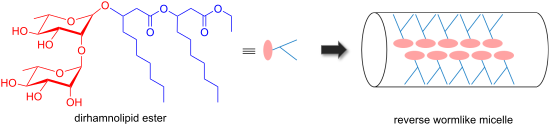
Figure 9: Schematic representation of the formation of RWLM by dirhamnolipid esters.
Beilstein J. Org. Chem. 2020, 16, 2687–2700, doi:10.3762/bjoc.16.219
Graphical Abstract
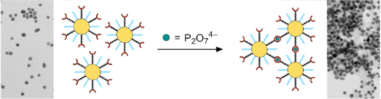
Figure 1: Schematic illustration of the analyte-induced crosslinking of gold nanoparticles containing a mixtu...
Scheme 1: Syntheses of the ligands rac-1 and (R)-1. Conditions: i) TsCl, NaOH, THF, 0 °C, 60 min → 25 °C, 80 ...
Scheme 2: Synthesis of ligand 2. Conditions: i) potassium phthalimide, DMF, 25 °C, 18 h, 67%; ii) 2,2'-dipico...
Figure 2: Photographs of solutions of NPrac-1 in water (0.25 mg/mL) containing different sodium salts at a co...
Figure 3: Sections of the 1H NMR spectra of solutions of NP25 in D2O/CD3OD 1:2 (v/v) between 8.9 and 3.9 ppm ...
Figure 4: Images of vials containing solutions of NP10-Zn (0.25 mg/mL) in water/methanol 1:2 (v/v) and additi...
Figure 5: Photograph of the solutions of the competition experiment. Vial (a) only contained NP10-Zn (and the...
Figure 6: UV–vis spectra of NP10-Zn (0.25 mg/mL in the initial measurement) in water/methanol 1:2 (v/v) conta...
Figure 7: TEM images of NP10-Zn (0.25 mg/mL) in water/methanol 1:2 (v/v) before (a) and after the addition of...
Beilstein J. Org. Chem. 2020, 16, 2645–2662, doi:10.3762/bjoc.16.215
Graphical Abstract
Figure 1: Common terminology and anatomy of a theoretical glycan, (KJ(IH)GF(D(E)(C)B)A. In this figure, we de...
Figure 2: Monosaccharide reachability analysis. (A) Clusters contain monosaccharides with highly similar ster...
Beilstein J. Org. Chem. 2020, 16, 2505–2522, doi:10.3762/bjoc.16.203
Graphical Abstract
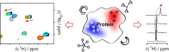
Figure 1: Ligands targeting charged areas on protein surfaces discussed in this review. The protein shown as ...
Figure 2: 1H NMR titration of lysine with tweezers. All signals show chemical shift perturbations and differe...
Figure 3: 1H,15N-HSQC Titration of full-length hPin1 with supramolecular tweezers (original data). (a) Spectr...
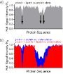
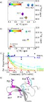
Figure 4: Relative signal intensities can be used to identify ligand binding sites (schematic representation ...
Figure 5: Schematic 1H,15N-HSQC spectrum of tauF4 (chemical shifts from BMRB # 17945, [109]) with and without spec...
Figure 6: H2(C)N spectra specific for arginine (a) and lysine (b) residues of the hPin1-WW domain at differen...
Beilstein J. Org. Chem. 2020, 16, 2484–2504, doi:10.3762/bjoc.16.202
Graphical Abstract
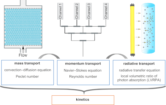
Figure 1: The momentum transport affects the mass transfer and the light field. All transport phenomena need ...
Figure 2: Common photomicroreactor designs: (a) Straight channel, (b) serpentine channel, (c) square serpenti...
Figure 3: Benchmarked photoreactors: (a) Microcapillaries in parallel, (b) microcapillaries in series, (c) fl...
Figure 4: Photochemical reactions that are detailed in Table 1.
Figure 5: Structured reactors designed for enhancing the mass transfer: (a) Packed bed photoreactor, (b) mono...
Figure 6: Comparison of the LED board designs of photomicroreactors: (a) CC array design, (b) MC array design...
Figure 7: Illustration of the light scattering phenomenon inside a photocatalytic flow reactor.
Figure 8: Efficiency of the absorption process in scattering situations with respect to pure absorption situa...
Figure 9: Different types of distributors: (a) Traditional or consecutive manifold, (b) bifurcation unit dist...
Beilstein J. Org. Chem. 2020, 16, 2448–2468, doi:10.3762/bjoc.16.199
Graphical Abstract
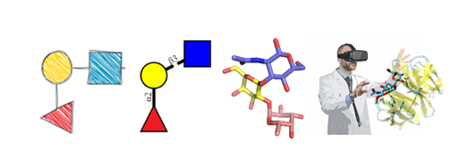
Figure 1: Levels of representation of glycans: from sketching to virtual reality.
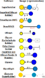
Figure 2: Depiction of lactose by various glycan sketching tools.
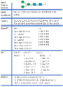
Figure 3: Examples of different glycan structure text formats for the same glycan. Data in these formats are ...
Figure 4: From top to bottom: SugarSketcher [36] interface with a glycan structure drawn using the “Quick Mode”. ...
Figure 5: GlyTouCan [38] interface allows to search for glycans structures in the database. Data contained in Gly...
Figure 6: From top to bottom: GlycanBuilder2 [46] interface with a glycan image in SNFG notation. Original Glycan...
Figure 7: From top to bottom: DrawGlycan-SNFG [51] web interface with a glycan text input and the resulting image...
Figure 8: From top to bottom: Glyco.me SugarBuilder [56] interface with a glycan structure showing options to def...
Figure 9: From top to bottom: Sweet II [62] web-interface with a text input to generate a 3D model. GLYCAM Carboh...
Figure 10: PolysGlycanBuilder [77] interface illustrating glycan drawing using SNFG symbols. The glycan can be fur...
Figure 11: From top to bottom: 3D-SNFG representation of glycan using 3D-SNFG script integrated VMD [79]. LiteMol [80]...
Beilstein J. Org. Chem. 2020, 16, 2346–2362, doi:10.3762/bjoc.16.196
Graphical Abstract
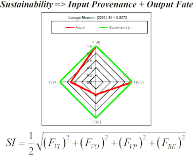
Figure 1: Radial diamond diagrams illustrating the sustainability index (SI) computed based on FVI, FVO, FVP,...
Beilstein J. Org. Chem. 2020, 16, 2151–2192, doi:10.3762/bjoc.16.183
Graphical Abstract
Figure 1: Fluorine-containing drugs.
Figure 2: Fluorinated agrochemicals.
Scheme 1: Selectivity of fluorination reactions.
Scheme 2: Different mechanisms of photocatalytic activation. Sub = substrate.
Figure 3: Jablonski diagram showing visible-light-induced energy transfer pathways: a) absorption, b) IC, c) ...
Figure 4: Schematic illustration of TTET.
Figure 5: Organic triplet PSCats.
Figure 6: Additional organic triplet PSCats.
Figure 7: A) Further organic triplet PSCats and B) transition metal triplet PSCats.
Figure 8: Different fluorination reagents grouped by generation.
Scheme 3: Synthesis of Selectfluor®.
Scheme 4: General mechanism of PS TTET C(sp3)–H fluorination.
Scheme 5: Selective benzylic mono- and difluorination using 9-fluorenone and xanthone PSCats, respectively.
Scheme 6: Chen’s photosensitized monofluorination: reaction scope.
Scheme 7: Chen’s photosensitized benzylic difluorination reaction scope.
Scheme 8: Photosensitized monofluorination of ethylbenzene on a gram scale.
Scheme 9: Substrate scope of Tan’s AQN-photosensitized C(sp3)–H fluorination.
Scheme 10: AQN-photosensitized C–H fluorination reaction on a gram scale.
Scheme 11: Reaction mechanism of the AQN-assisted fluorination.
Figure 9: 3D structures of the singlet ground and triplet excited states of Selectfluor®.
Scheme 12: Associated transitions for the activation of acetophenone by violet light.
Scheme 13: Ethylbenzene C–H fluorination with various PSCats and conditions.
Scheme 14: Effect of different PSCats on the C(sp3)–H fluorination of cyclohexane (39).
Scheme 15: Reaction scope of Chen’s acetophenone-photosensitized C(sp3)–H fluorination reaction.
Figure 10: a) Site-selectivity of Chen’s acetophenone-photosensitized C–H fluorination reaction [201]. b) Site-sele...
Scheme 16: Formation of the AQN–Selectfluor® exciplex Int1.
Scheme 17: Generation of the C3 2° pentane radical and the Selectfluor® N-radical cation from the exciplex.
Scheme 18: Hydrogen atom abstraction by the Selectfluor® N-radical cation from pentane to give the C3 2° penta...
Scheme 19: Fluorine atom transfer from Selectfluor® to the C3 2° pentane radical to yield 3-fluoropentane and ...
Scheme 20: Barrierless fluorine atom transfer from Int1 to the C3 2° pentane radical to yield 3-fluoropentane,...
Scheme 21: Ketone-directed C(sp3)–H fluorination.
Scheme 22: Ketone-directed fluorination through a 5- and a 6-membered transition state, respectively.
Scheme 23: Effect of different PSCats on the photosensitized C(sp3)–H fluorination of 47.
Scheme 24: Substrate scope of benzil-photoassisted C(sp3)–H fluorinations.
Scheme 25: A) Benzil-photoassisted enone-directed C(sp3)–H fluorination. B) Classification of the reaction mod...
Scheme 26: A) Xanthone-photoassisted ketal-directed C(sp3)–H fluorination. B) Substrate scope. C) C–H fluorina...
Scheme 27: Rationale for the selective HAT at the C2 C–H bond of galactose acetonide.
Scheme 28: Photosensitized C(sp3)–H benzylic fluorination of a peptide using different PSCats.
Scheme 29: Peptide scope of 5-benzosuberenone-photoassisted C(sp3)–H fluorinations.
Scheme 30: Continuous flow PS TTET monofluorination of 72.
Scheme 31: Photosensitized C–H fluorination of N-butylphthalimide as a PSX.
Scheme 32: Substrate scope and limitations of the PSX C(sp3)–H monofluorination.
Scheme 33: Substrate crossover monofluorination experiment.
Scheme 34: PS TTET mechanism proposed by Hamashima and co-workers.
Scheme 35: Photosensitized TFM of 78 to afford α-trifluoromethylated ketone 80.
Scheme 36: Substrate scope for photosensitized styrene TFM to give α-trifluoromethylated ketones.
Scheme 37: Control reactions for photosensitized TFM of styrenes.
Scheme 38: Reaction mechanism for photosensitized TFM of styrenes to afford α-trifluoromethylated ketones.
Scheme 39: Reaction conditions for TFMs to yield the cis- and the trans-product, respectively.
Scheme 40: Substrate scope of trifluoromethylated (E)-styrenes.
Scheme 41: Strategies toward trifluoromethylated (Z)-styrenes.
Scheme 42: Substrate scope of trifluoromethylated (Z)-styrenes.
Scheme 43: Reaction mechanism for photosensitized TFM of styrenes to afford E- or Z-products.
Beilstein J. Org. Chem. 2020, 16, 2046–2056, doi:10.3762/bjoc.16.171
Graphical Abstract
Figure 1: Representative structures of the plant N-glycans studied in this work with corresponding nomenclatu...
Figure 2: A representative structure of the non-galactosylated N-glycan with α(1-3)-linked core fucose (ngf) ...
Figure 3: β-D-xylose ring pucker analysis over 3 μs of cumulative MD sampling of the ngx N-glycan. The two sn...
Figure 4: Comparison of the different conformational equilibria of the (1-6) arm in a core α(1-3)-Fuc β(1-2)-...
Figure 5: Conformational analysis of the (1-6) arm in four hybrid N-glycoforms, β(1-2)-xylosylated A2G2 (top-...
Figure 6: Conformational equilibrium of the (1-6) arm in terms of phi/psi torsion angle values for the α(1-3)...
Figure 7: List of 3D structural units of monosaccharides (glycoblocks) that regulate the 3D architecture and ...