

Search results
Search for "Grignard reagent" in Full Text gives 115 result(s) in Beilstein Journal of Organic Chemistry.
An overview of the key routes to the best selling 5-membered ring heterocyclic pharmaceuticals
- Marcus Baumann,
- Ian R. Baxendale,
- Steven V. Ley and
- Nikzad Nikbin
Beilstein J. Org. Chem. 2011, 7, 442–495, doi:10.3762/bjoc.7.57
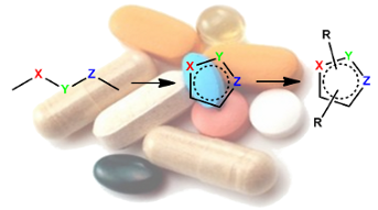

Graphical Abstract
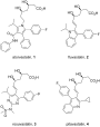
Figure 1: Structures of atorvastatin and other commercial statins.

Figure 2: Structure of compactin.

Scheme 1: Synthesis of pentasubstituted pyrroles.

Scheme 2: [3 + 2] Cycloaddition to prepare 5-isopropylpyrroles.

Scheme 3: Regiospecific [3 + 2] cycloaddition to prepare the pyrrole scaffold.

Scheme 4: Formation of the pyrrole core of atorvastatin via [3 + 2] cycloaddition.

Scheme 5: Formation of pyrrole 33 via the Paal–Knorr reaction.

Scheme 6: Convergent synthesis towards atorvastatin.

Figure 3: Binding pocket of sunitinib in the TRK KIT.

Scheme 7: Synthesis of sunitinib.

Scheme 8: Alternative synthesis of sunitinib.

Scheme 9: Key steps in the syntheses of sumatriptan and zolmitriptan.

Scheme 10: Introduction of the N,N-dimethylaminoethyl side chain.

Scheme 11: Japp–Klingemann reaction in the synthesis of sumatriptan.

Scheme 12: Synthesis of the intermediate sulfonyl chlorides 62 and 63.

Scheme 13: Alternative introduction of the sulfonamide.

Scheme 14: Negishi-type coupling to benzylic sulfonamides.

Scheme 15: Heck reaction used to introduce the sulfonamide side chain of naratriptan.

Scheme 16: Synthesis of the oxazolinone appendage of zolmitriptan.

Scheme 17: Grandberg indole synthesis used in the preparation of rizatriptan.

Scheme 18: Improved synthesis of rizatriptan.

Scheme 19: Larock-type synthesis of rizatriptan.

Scheme 20: Synthesis of eletriptan.

Scheme 21: Heck coupling for the indole system in eletriptan.

Scheme 22: Attempted Fischer indole synthesis of elatriptan.

Scheme 23: Successful Fischer indole synthesis for eletriptan.

Scheme 24: Mechanistic rationale for the Bischler–Möhlau reaction.

Scheme 25: Bischler-type indole synthesis used in the fluvastatin sodium synthesis.

Scheme 26: Palladium-mediated synthesis of ondansetron.

Scheme 27: Fischer indole synthesis of ondansetron.

Scheme 28: Optimised Pictet–Spengler reaction towards tadalafil.

Figure 4: Structures of carvedilol 136 and propranolol 137.

Scheme 29: Synthesis of the carbazole core of carvedilol.

Scheme 30: Alternative syntheses of 4-hydroxy-9H-carbazole.

Scheme 31: Convergent synthesis of etodolac.

Scheme 32: Alternative synthesis of etodolac.

Figure 5: Structures of imidazole-containing drugs.

Scheme 33: Synthesis of functionalised imidazoles towards losartan.

Scheme 34: Direct synthesis of the chlorinated imidazole in losartan.

Scheme 35: Synthesis of trisubstituted imidazoles.

Scheme 36: Preparation of the imidazole ring in olmesartan.

Scheme 37: Synthesis of ondansetron.

Scheme 38: Alternative route to ondansetron and its analogues.

Scheme 39: Proton pump inhibitors and synthesis of esomeprazole.

Scheme 40: Synthesis of benzimidazole core pantoprazole.

Figure 6: Structure of rabeprazole 194.

Scheme 41: Synthesis of candesartan.

Scheme 42: Alternative access to the candesartan key intermediate 216.

Scheme 43: .Medicinal chemistry route to telmisartan.

Scheme 44: Improved synthesis of telmisartan.

Scheme 45: Synthesis of zolpidem.

Scheme 46: Copper-catalysed 3-component coupling towards zolpidem.

Figure 7: Structure of celecoxib.

Scheme 47: Preparation of celecoxib.

Scheme 48: Alternative synthesis of celecoxib.

Scheme 49: Regioselective access to celecoxib.

Scheme 50: Synthesis of pazopanib.

Scheme 51: Syntheses of anastrozole, rizatriptan and letrozole.

Scheme 52: Regioselective synthesis of anastrozole.

Scheme 53: Triazine-mediated triazole formation towards anastrozole.

Scheme 54: Alternative routes to 1,2,4-triazoles.

Scheme 55: Initial synthetic route to sitagliptin.

Figure 8: Binding of sitagliptin within DPP-IV.

Scheme 56: The process route to sitagliptin key intermediate 280.

Scheme 57: Synthesis of maraviroc.

Scheme 58: Synthesis of alprazolam.

Scheme 59: The use of N-nitrosoamidine derivatives in the preparation of fused benzodiazepines.

Figure 9: Structures of itraconazole, ravuconazole and voriconazole.

Scheme 60: Synthesis of itraconazole.

Scheme 61: Synthesis of rufinamide.

Scheme 62: Representative tetrazole formation in valsartan.

Figure 10: Structure of tetrazole containing olmesartan, candesartan and irbesartan.

Scheme 63: Early stage introduction of the tetrazole in losartan.

Scheme 64: Synthesis of cilostazol.

Figure 11: Structure of cefdinir.

Scheme 65: Semi-synthesis of cefdinir.

Scheme 66: Thiazole syntheses towards ritonavir.

Scheme 67: Synthesis towards pramipexole.

Scheme 68: Alternative route to pramipexole.

Scheme 69: Synthesis of famotidine.

Scheme 70: Efficient synthesis of the hyperuricemic febuxostat.

Scheme 71: Synthesis of ziprasidone.

Figure 12: Structure of mometasone.

Scheme 72: Industrial access to 2-furoic acid present in mometasone.

Scheme 73: Synthesis of ranitidine from furfuryl alcohol.

Scheme 74: Synthesis of nitrofurantoin.

Scheme 75: Synthesis of benzofuran.

Scheme 76: Synthesis of amiodarone.

Scheme 77: Synthesis of raloxifene.

Scheme 78: Alternative access to the benzo[b]thiophene core of raloxifene.

Scheme 79: Gewald reaction in the synthesis of olanzapine.

Scheme 80: Alternative synthesis of olanzapine.
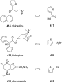
Figure 13: Access to simple thiophene-containing drugs.

Scheme 81: Synthesis of clopidogrel.

Scheme 82: Pictet–Spengler reaction in the preparation of tetrahydrothieno[3,2-c]pyridine (422).

Scheme 83: Alternative synthesis of key intermediate 422.

Figure 14: Co-crystal structures of timolol (left) and carazolol (right) in the β-adrenergic receptor.

Scheme 84: Synthesis of timolol.

Scheme 85: Synthesis of tizanidine 440.

Scheme 86: Synthesis of leflunomide.

Scheme 87: Synthesis of sulfamethoxazole.

Scheme 88: Synthesis of risperidone.

Figure 15: Relative abundance of selected transformations.

Figure 16: The abundance of heterocycles within top 200 drugs (5-membered rings).
The preparation of 3-substituted-1,5-dibromopentanes as precursors to heteracyclohexanes
- Bryan Ringstrand,
- Martin Oltmanns,
- Jeffrey A. Batt,
- Aleksandra Jankowiak,
- Richard P. Denicola and
- Piotr Kaszynski
Beilstein J. Org. Chem. 2011, 7, 386–393, doi:10.3762/bjoc.7.49
- typically obtained from I or from II by reaction with Na2S [9][10][12][13], whereas the silacyclohexanes V and phosphorinanes VI are prepared by reacting the Grignard reagent derived from I with dichlorosilanes [14] or phosphonous dichlorides [15], respectively (Figure 1). Our research program focuses on
- % [17][38]. The downside to Method 1C is that an excess of Grignard reagent (3–4 equiv) is required; therefore, it is not economical with respect to the alkyl halide. Method 1D also uses glutaconate diester, which is reacted with an aryl iodide in the presence of Pd(0) under Heck conditions. The
- addition of a Grignard reagent to tetrahydro-4H-pyran-4-one, elimination of water, and hydrogenation of the olefin (Method 2A). Typical yields for Method 2A range from 20–30% [39][40]. The second route is the Wittig olefination of tetrahydro-4H-pyran-4-one followed by hydrogenation (Method 2B). Yields for

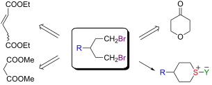
Graphical Abstract

Figure 1: Methods for synthesis of dibromides I and their use for preparation of 6-membered heterocycles.

Scheme 1: General methods for preparation of diols VII.

Scheme 2: General methods for preparation of tetrahydropyrans VIII.

Figure 2: Structures of 1,5-dibromomopentanes 1a–1d.

Scheme 3: Preparation of dibromides 1.

Scheme 4: Preparation of diol 2a.

Scheme 5: Preparation of diol 2b.

Scheme 6: Preparation of tetrahydropyrans 3a–3c.

Scheme 7: Preparation of tetrahydropyran 3d.

Scheme 8: Preparation of methylenetetrahydropyrans 6.

Scheme 9: Preparation of bromides 8 and 10.
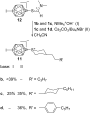
Scheme 10: Preparation of sulfonium derivatives 11.
Photocycloaddition of aromatic and aliphatic aldehydes to isoxazoles: Cycloaddition reactivity and stability studies
- Axel G. Griesbeck,
- Marco Franke,
- Jörg Neudörfl and
- Hidehiro Kotaka
Beilstein J. Org. Chem. 2011, 7, 127–134, doi:10.3762/bjoc.7.18
- and benzaldehyde, while at −78 °C, no reaction could be observed. In contrast, the use of an excess of Grignard reagent (3 equiv) at −78 °C again led to decomposition. The application of boron trifluoride at −78 °C also led to decomposition, followed by a normal nucleophilic attack of the Grignard
- reagent on the liberated benzaldehyde. Conclusion The photocycloaddition of electronically excited carbonyl compounds to isoxazoles is clearly less effective than with other five-membered aromatic or non-aromatic heterocycles (furans, thiophenes, pyrroles, oxazoles, dihydrofurans, dihydropyrroles) [1

Graphical Abstract
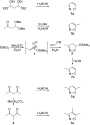
Scheme 1: Synthetic routes to isoxazoles 7a–7e.

Scheme 2: Synthetic routes to isoxazoles 7f–7h.

Scheme 3: Benzaldehyde photocycloaddition to 7a–7e.

Scheme 4: Photochemical ring contraction of isoxazoles 7f–7h.

Scheme 5: Photocycloaddition of aromatic aldehydes to di- and trimethyl isoxazoles 7d and 7e.

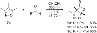
Scheme 6: Preparative photocycloadditions of 7e with aromatic aldehydes.

Figure 1: Structures of the photoproducts 9a–9c in the crystal.

Scheme 7: T-type photochromism of isoxazole–aldehyde pairs.

Scheme 8: Reductive cleavage of the trimethylisoxazole adduct 9a.
Aromatic and heterocyclic perfluoroalkyl sulfides. Methods of preparation
- Vladimir N. Boiko
Beilstein J. Org. Chem. 2010, 6, 880–921, doi:10.3762/bjoc.6.88
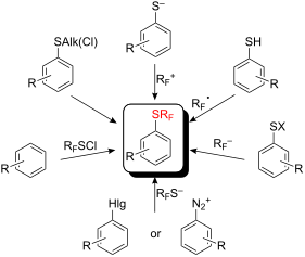

Graphical Abstract

Figure 1: Examples of industrial fluorine-containing bio-active molecules.

Figure 2: CF3(S)- and CF3(O)-containing pharmacologically active compounds.

Figure 3: Hypotensive candidates with SRF and SO2RF groups – analogues of Losartan and Nifedipin.

Figure 4: The variety of the pharmacological activity of RFS-substituted compounds.

Figure 5: Recent examples of compounds containing RFS(O)n-groups [12-18].

Scheme 1: Fluorination of ArSCCl3 to corresponding ArSCF3 derivatives. For references see: a[38-43]; b[41,42]; c[43]; d[44]; e[38-43,45-47]; f[38-43,48,49]; g...

Scheme 2: Preparation of aryl pentafluoroethyl sulfides.

Scheme 3: Mild fluorination of the aryl SCF2Br derivatives.

Scheme 4: HF fluorinations of aryl α,α,β-trichloroisobutyl sulfide at various conditions.

Scheme 5: Monofluorination of α,α-dichloromethylene group.

Scheme 6: Electrophilic substitution of phenols with CF3SCl [69].

Scheme 7: Introduction of SCF3 groups into activated phenols [71-74].

Scheme 8: Preparation of tetrakis(SCF3)-4-methoxyphenol [72].

Scheme 9: The interactions of resorcinol and phloroglucinol derivatives with RFSCl.

Scheme 10: Reactions of anilines with CF3SCl.

Scheme 11: Trifluoromethylsulfanylation of anilines with electron-donating groups in the meta position [74].

Scheme 12: Reaction of benzene with CF3SCl/CF3SO3H [77].

Scheme 13: Reactions of trifluoromethyl sulfenyl chloride with aryl magnesium and -mercury substrates.

Scheme 14: Reactions of pyrroles with CF3SCl.

Scheme 15: Trifluoromethylsulfanylation of indole and indolizines.

Scheme 16: Reactions of N-methylpyrrole with CF3SCl [80,82].

Scheme 17: Reactions of furan, thiophene and selenophene with CF3SCl.

Scheme 18: Trifluoromethylsulfanylation of imidazole and thiazole derivatives [83].

Scheme 19: Trifluoromethylsulfanylation of pyridine requires initial hydride reduction.

Scheme 20: Introduction of additional RFS-groups into heterocyclic compounds in the presence of CF3SO3H.

Scheme 21: Introduction of additional RFS-groups into pyrroles [82,87].

Scheme 22: By-products in reactions of pyrroles with CF3SCl [82].

Scheme 23: Reaction of aromatic iodides with CuSCF3 [93,95].

Scheme 24: Reaction of aromatic iodides with RFZCu (Z = S, Se), RF = CF3, C6F5 [93,95,96].

Scheme 25: Side reactions during trifluoromethylsulfanylation of aromatic iodides with CF3SCu [98].

Scheme 26: Reactions with in situ generated CuSCF3.

Scheme 27: Perfluoroalkylthiolation of aryl iodides with bulky RFSCu [105].

Scheme 28: In situ formation and reaction of RFZCu with aryl iodides.

Figure 6: Examples of compounds obtained using in situ generated RFZCu methodology [94].

Scheme 29: Introduction of SCF3 group into aromatics via difluorocarbene.

Scheme 30: Tetrakis(dimethylamino)ethylene dication trifluoromethyl thiolate as a stable reagent for substitut...

Scheme 31: The use of CF2=S/CsF or (CF3S)2C=S/CsF for the introduction of CF3S groups into fluorinated heteroc...

Scheme 32: One-pot synthesis of ArSCF3 from ArX, CCl2=S and KF.

Scheme 33: Reaction of aromatics with CF3S− Kat+ [115].

Scheme 34: Reactions of activated aromatic chlorides with AgSCF3/KI.

Scheme 35: Comparative CuSCF3/KI and Hg(SCF3)2/KI reactions.

Scheme 36: Me3SnTeCF3 – a reagent for the introduction of the TeCF3 group.

Scheme 37: Sandmeyer reactions with CuSCF3.

Scheme 38: Reactions of perfluoroalkyl iodides with alkali and organolithium reagents.

Scheme 39: Perfluoroalkylation with preliminary breaking of the disulfide bond.

Scheme 40: Preparation of RFS-substituted anilines from dinitrodiphenyl disulfides.

Scheme 41: Photochemical trifluoromethylation of 2,4,6-trimercaptochlorobenzene [163].

Scheme 42: Putative process for the formation of B, C and D.

Scheme 43: Trifluoromethylation of 2-mercapto-4-hydroxy-6-trifluoromethylyrimidine [145].

Scheme 44: Deactivation of 2-mercapto-4-hydroxypyrimidines S-centered radicals.

Scheme 45: Perfluoroalkylation of thiolates with CF3Br under UV irradiation.

Scheme 46: Catalytic effect of methylviologen for RF• generation.

Scheme 47: SO2−• catalyzed trifluoromethylation.

Scheme 48: Electrochemical reduction of CF3Br in the presence of SO2 [199,200].

Scheme 49: Participation of SO2 in the oxidation of ArSCF3−•.

Scheme 50: Electron transfer cascade involving SO2 and MV.

Scheme 51: Four stages of the SRN1 mechanism for thiol perfluoroalkylation.

Scheme 52: A double role of MV in the catalysis of RFI reactions with aryl thiols.

Scheme 53: Photochemical reaction of pentafluoroiodobenzene with trifluoromethyl disulfide.

Scheme 54: N- Trifluoromethyl-N-nitrosobenzene sulfonamide – a source of CF3• radicals [212,213].

Scheme 55: Radical trifluoromethylation of organic disulfides with ArSO2N=NCF3.

Scheme 56: Barton’s S-perfluoroalkylation reactions [216].

Scheme 57: Decarboxylation of thiohydroxamic esters in the presence of C6F13I.

Scheme 58: Reactions of thioesters of trifluoroacetic and trifluoromethanesulfonic acids in the presence of ar...

Scheme 59: Perfluoroalkylation of polychloropyridine thiols with xenon perfluorocarboxylates or XeF2 [222,223].

Scheme 60: Interaction of Xe(OCORF)2 with nitroaryl disulfide [227].

Scheme 61: Bi(CF3)3/Cu(OCOCH3)2 trifluoromethylation of thiophenolate [230].

Scheme 62: Reaction of fluorinated carbanions with aryl sulfenyl chlorides.

Scheme 63: Reaction of methyl perfluoromethacrylate with PhSCl in the presence of fluoride.

Scheme 64: Reactions of ArSCN with potassium and magnesium perfluorocarbanions [237].

Scheme 65: Reactions of RFI with TDAE and organic disulfides [239,240].

Scheme 66: Decarboxylation of perfluorocarboxylates in the presence of disulfides [245].

Scheme 67: Organization of a stable form of “CF3−” anion in the DMF.

Scheme 68: Silylated amines in the presence of fluoride can deprotonate fluoroform for reaction with disulfide...

Figure 7: Other examples of aminomethanols [264].

Scheme 69: Trifluoromethylation of diphenyl disulfide with PhSO2CF3/t-BuOK.

Scheme 70: Amides of trifluoromethane sulfinic acid are sources of CF3− anion.

Scheme 71: Trifluoromethylation of various thiols using “hyper-valent” iodine (III) reagent [279].

Scheme 72: Trifluoromethylation of p-nitrothiophenolate with diaryl CF3 sulfonium salts [280].

Scheme 73: Trifluoromethyl transfer from dibenzo (CF3)S-, (CF3)Se- and (CF3)Te-phenium salts to thiolates [283].

Scheme 74: Multi-stage paths for synthesis of dibenzo-CF3-thiophenium salts [61].
Recent advances in carbocupration of α-heterosubstituted alkynes
- Ahmad Basheer and
- Ilan Marek
Beilstein J. Org. Chem. 2010, 6, No. 77, doi:10.3762/bjoc.6.77

- -pyridylsilylalkyne is used, does the copper-catalyzed carbomagnesiation reaction proceed with the formation of the corresponding Grignard reagent. To prove the involvement of the pyridyl coordination, the 3- and 4-pyridylsilyl- and phenylsilyl substituted substrates were prepared and treated under similar reaction
- assumption, the carbometalated adduct was obtained in 83% yield even when using an equimolar amount of CuI with 2.0 equiv of PhMgI. Moreover, yields are drastically affected by the nature of the aryl Grignard reagent used (PhMgI, 74%; PhMgBr, 27%; PhMgCl, 0%; Ph2Mg, 0%): other Grignard derivatives were not

Graphical Abstract

Scheme 1: General scheme for the carbocupration reaction.

Scheme 2: Regioselectivity in the carbocupration reaction.

Scheme 3: Carbocupration of α-alkoxyalkynes.

Scheme 4: Carbocupration of substituted α-alkoxyalkynes.

Scheme 5: Formation of the branched isomer.

Scheme 6: Formation of the linear isomer.

Scheme 7: Carbocupration of O-alkynyl carbamates.

Scheme 8: Carbocupration of ynamines.

Scheme 9: Carbocupration of ynamide.

Scheme 10: Formation of aldol products possessing stereogenic quaternary carbon centers.

Scheme 11: Carbocupration of alkynyl sulfonamide.

Scheme 12: Tandem carbocupration-sigmatropic rearrangement.

Scheme 13: Silylcupration of alkynyl sulfonamides.

Scheme 14: Carbocupration of P-substituted alkynes.

Scheme 15: Carbocupration of alkynylphosphonates.

Scheme 16: Carbocupration of thioalkynes.

Scheme 17: Tandem carbocupration-1,2-metalate rearrangement.

Scheme 18: Carbocupration with functionalized organocopper species.

Scheme 19: Carbocupration of alkynyl sulfoxides.

Scheme 20: Carbocupration of alkynyl sulfones.

Scheme 21: Carbocupration of alkynyl sulfoximines.

Scheme 22: Carbocupration of alkynylsilanes.

Scheme 23: Carbocupration of functionalized alkynylsilanes.

Scheme 24: Silyl- and stannyl cupration of silyl- and stannylalkynes.
Synthesis and properties of calix[4]arene telluropodant ethers as Ag+ selective sensors and Ag+, Hg2+ extractants
- Yang Lu,
- Yuanyuan Li,
- Song He,
- Yan Lu,
- Changying Liu,
- Xianshun Zeng and
- Langxing Chen
Beilstein J. Org. Chem. 2009, 5, No. 59, doi:10.3762/bjoc.5.59
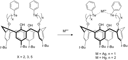
- literature procedures. 25,27-Dihydroxy-26,28-bis(phenyltelluropropoxy)-5,11,17,23-tetra-tert-butylcalix[4]arene 6 Diphenyl ditelluride (512 mg, 1.25 mmol), prepared from phenyl Grignard reagent with tellurium powder in 78% yield, was dissolved in ethanol (30 ml) and benzene (30 ml) in a 100 ml round-bottomed

Graphical Abstract

Scheme 1: Synthesis and structures of calix[4]arenes 6–8; 3, 6: n = 2; 4, 7: n = 3; 5, 8: n = 5.

Scheme 2: Synthesis of calix[4]arene 10 and 12.
Preparation and Diels–Alder/cross coupling reactions of a 2-diethanolaminoboron- substituted 1,3-diene
- Liqiong Wang,
- Cynthia S. Day,
- Marcus W. Wright and
- Mark E. Welker
Beilstein J. Org. Chem. 2009, 5, No. 45, doi:10.3762/bjoc.5.45
- greenish black. The mixture was heated to reflux for an additional 30 min after completion of the addition. The Grignard reagent thus obtained was immediately added dropwise to a solution of trimethoxyborane (4.25 mL, 38.5 mmol) in THF (25 mL) using a double-ended needle. The addition was controlled in
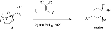
- have begun to prepare diethanolaminoboron substituted dienes and we communicate our first results in this area here. Results and Discussion The diethanolamine boronyl substituted diene 2 was obtained as white needles on a several gram scale from a simple procedure which involved preparing the Grignard
- reagent from chloroprene 1, adding this reagent to trimethoxyborane followed by the addition of dilute HCl and diethanolamine (Scheme 1). The boron substituted diene 2 thus obtained has C1 (δ 5.23 vs δ 5.04, 4.96 (d6-DMSO) and C3 (δ 6.31 vs. δ 6.19) hydrogen atoms which are significantly more deshielded

Graphical Abstract

Scheme 1: Synthesis of 2-diethanolaminoborate-1,3-butadiene.

Figure 1: Molecular structure of boron substituted diene 2.

Scheme 2: Diels–Alder reactions.

Scheme 3: Cross coupling reactions.
From discovery to production: Scale- out of continuous flow meso reactors
- Peter Styring and
- Ana I. R. Parracho
Beilstein J. Org. Chem. 2009, 5, No. 29, doi:10.3762/bjoc.5.29
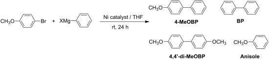
- vessel 1. The reaction studied was the Kumada reaction [11][12] which involves the coupling of an aryl halide and a Grignard reagent, in this case 4-bromoanisole and phenylmagnesium chloride, to produce 4-methoxybiphenyl (4-MeOBP, R-Ar). It was also observed that anisole, 4′,4-dimethoxybyphenyl (4,4′-di
- -MeOBP, Ar-Ar) and biphenyl (BP, R-R) were obtained as reaction by-products. The catalytic cycle that we originally proposed [6] neglects the formation of the other by-products so we investigated the whole scheme in detail. The chloro rather than the bromo Grignard reagent was used, even though it was
- probe the mechanism for the reaction further. If the activation of the catalyst was important then a pre-wash with the Grignard reagent should improve the yield of the desired cross-coupled product. This was indeed found to be the case. Without any pre-wash or with a 4-bromoanisole pre-wash there was no

Graphical Abstract

Scheme 1: Synthesis of 4-methoxybiphenyl (4-MeOBP) and by-products in the Kumada reaction.

Figure 1: Stainless steel single column flow reactor for discovery scale synthesis.

Figure 2: (a): Schematic diagram of the parallel reactor housing (dimensions in mm); (b) the stainless steel ...

Figure 3: Schematic diagram of the pneumatic pumping system.

Scheme 2: Proposed catalytic cycles for the transformation of 4-haloanisole (Ar-X) and Grignard reagent (RMgX...

Figure 4: Comparative study of flow rates in a single channel meso flow reactor. The output was sampled hourl...

Figure 5: Kumada reaction carried out in a parallel channel meso reactor at a flow rate of 95 ml h−1.

Figure 6: Kumada reaction carried out in a parallel channel meso reactor over a 31-hour period at a flow rate...

Figure 7: Kumada reaction carried out in a parallel channel meso reactor at a flow rate of 190 ml h−1.
Continuous flow based catch and release protocol for the synthesis of α-ketoesters
- Alessandro Palmieri,
- Steven V. Ley,
- Anastasios Polyzos,
- Mark Ladlow and
- Ian R. Baxendale
Beilstein J. Org. Chem. 2009, 5, No. 23, doi:10.3762/bjoc.5.23
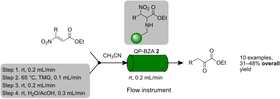
- important products in their own right [82][83][84][85][86][87][88]. Common methods for the preparation of α-ketoesters include the modified Dakin-West reaction [89] and the addition of a Grignard reagent to oxalates or oxalyl chlorides [90][91][92] together with a few alternative syntheses [93][94][95][96

Graphical Abstract

Figure 1: The Uniqsis FlowSyn™ continuous flow reactor comprising of a column holder and heating unit (A) and...

Scheme 1: General procedure for the flow synthesis of α-ketoester products 4a–j.

Scheme 2: General procedure for the batch synthesis of nitroolefinic esters 1a–j.

Scheme 3: General procedure for the flow synthesis of nitroolefinic esters 1a,c.

Figure 2: α-Ketoesters prepared and isolated yields.
Recent progress on the total synthesis of acetogenins from Annonaceae
- Nianguang Li,
- Zhihao Shi,
- Yuping Tang,
- Jianwei Chen and
- Xiang Li
Beilstein J. Org. Chem. 2008, 4, No. 48, doi:10.3762/bjoc.4.48
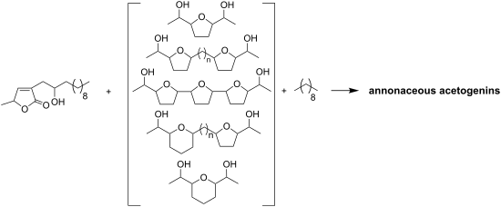
- by oxidation gave the aldehyde 191, which could readily be converted into the aldehyde 192. The bromide 193 was transformed into the corresponding Grignard reagent, which was allowed to react with the aldehyde 192 to afford the two epimers 194 and 195. The dianion of 196 was allowed to react with (S

Graphical Abstract

Scheme 1: Total synthesis of longifolicin by Marshall’s group.

Scheme 2: Total synthesis of corossoline by Tanaka’s group.

Scheme 3: Total synthesis of corossoline by Wu’s group.

Scheme 4: Total synthesis of pseudo-annonacin A by Hanessian’s group.

Scheme 5: Total synthesis of tonkinecin by Wu’s group.

Scheme 6: Total synthesis of gigantetrocin A by Shi’s group.

Scheme 7: Total synthesis of annonacin by Wu’s group.

Scheme 8: Total synthesis of solamin by Kitahara’s group.

Scheme 9: Total synthesis of solamin by Mioskowski’s group.

Scheme 10: Total synthesis of cis-solamin by Makabe’s group.

Scheme 11: Total synthesis of cis-solamin by Brown’s group.

Scheme 12: The formal synthesis of (+)-cis-solamin by Donohoe’s group.

Scheme 13: Total synthesis of cis-solamin by Stark’s group.

Scheme 14: Total synthesis of mosin B by Tanaka’s group.

Scheme 15: Total synthesis of longicin by Hanessian’s group.

Scheme 16: Total synthesis of murisolin and 16,19-cis-murisolin by Tanaka’s group.

Scheme 17: Synthesis of a stereoisomer library of (+)-murisolin by Curran’s group.

Scheme 18: Total synthesis of murisolin by Makabe’s group.

Scheme 19: Total synthesis of reticulatain-1 by Makabe’s group.

Scheme 20: Total synthesis of muricatetrocin C by Ley’s group.

Scheme 21: Total synthesis of (4R,12S,15S,16S,19R,20R,34S)-muricatetrocin (146) and (4R,12R,15S,16S,19R,20R,34S...

Scheme 22: Total synthesis of parviflorin by Hoye’s group.

Scheme 23: Total synthesis of parviflorin by Trost’s group.

Scheme 24: Total synthesis of trilobacin by Sinha’s group.

Scheme 25: Total synthesis of 15-epi-annonin I 181b by Scharf’s group.

Scheme 26: Total synthesis of squamocin A and squamocin D by Scharf’s group.

Scheme 27: Total synthesis of asiminocin by Marshall’s group.

Scheme 28: Total synthesis of asiminecin by Marshall’s group.

Scheme 29: Total synthesis of (+)-(30S)-bullanin by Marshall’s group.

Scheme 30: Total synthesis of uvaricin by the group of Sinha and Keinan.

Scheme 31: Formal synthesis of uvaricin by Burke’s group.

Scheme 32: Total synthesis of trilobin by Marshall’s group.

Scheme 33: Total synthesis of trilobin by the group of Sinha and Keinan.

Scheme 34: Total synthesis of asimilobin by the group of Wang and Shi.

Scheme 35: Total synthesis of squamotacin by the group of Sinha and Keinan.

Scheme 36: Total synthesis of asimicin by Marshall’s group.

Scheme 37: Total synthesis of asimicin by the group of Sinha and Keinan.

Scheme 38: Total synthesis of asimicin by Roush’s group.

Scheme 39: Total synthesis of asimicin by Marshall’s group.

Scheme 40: Total synthesis of 10-hydroxyasimicin by Ley’s group.

Scheme 41: Total synthesis of asimin by Marshall’s group.

Scheme 42: Total synthesis of bullatacin by the group of Sinha and Keinan.

Scheme 43: Total synthesis of bullatacin by Roush’s group.

Scheme 44: Total synthesis of bullatacin by Pagenkopf’s group.

Scheme 45: Total synthesis of rollidecins C and D by the group of Sinha and Keinan.

Scheme 46: Total synthesis of 30(S)-hydroxybullatacin by Marshall’s group.

Scheme 47: Total synthesis of uvarigrandin A and 5(R)-uvarigrandin A by Marshall’s group.

Scheme 48: Total synthesis of membranacin by Brown’s group.

Scheme 49: Total synthesis of membranacin by Lee’s group.

Scheme 50: Total synthesis of rolliniastatin 1 and rollimembrin by Lee’s group.

Scheme 51: Total synthesis of longimicin D by the group of Maezaki and Tanaka.

Scheme 52: Total synthesis of the structure proposed for mucoxin by Borhan’s group.

Scheme 53: Modular synthesis of adjacent bis-THF annonaceous acetogenins by Marshall’s group.

Scheme 54: Total synthesis of 4-deoxygigantecin by Tanaka’s group.

Scheme 55: Total synthesis of squamostatins D by Marshall’s group.

Scheme 56: Total synthesis of gigantecin by Crimmins’s group.

Scheme 57: Total synthesis of gigantecin by Hoye’s group.

Scheme 58: Total synthesis of cis-sylvaticin by Donohoe’s group.

Scheme 59: Total synthesis of 17(S),18(S)-goniocin by Sinha’s group.

Scheme 60: Total synthesis of goniocin and cyclogoniodenin T by the group of Sinha and Keinan.

Scheme 61: Total synthesis of jimenezin by Takahashi’s group.

Scheme 62: Total synthesis of jimenezin by Lee’s group.

Scheme 63: Total synthesis of jimenezin by Hoffmann’s group.

Scheme 64: Total synthesis of muconin by Jacobsen’s group.

Scheme 65: Total synthesis of (+)-muconin by Kitahara’s group.

Scheme 66: Total synthesis of muconin by Takahashi’s group.

Scheme 67: Total synthesis of muconin by the group of Yoshimitsu and Nagaoka.

Scheme 68: Total synthesis of mucocin by the group of Sinha and Keinan.

Scheme 69: Total synthesis of mucocin by Takahashi’s group.

Scheme 70: Total synthesis of (−)-mucocin by Koert’s group.

Scheme 71: Total synthesis of mucocin by the group of Takahashi and Nakata.

Scheme 72: Total synthesis of mucocin by Evans’s group.

Scheme 73: Total synthesis of mucocin by Mootoo’s group.

Scheme 74: Total synthesis of (−)-mucocin by Crimmins’s group.

Scheme 75: Total synthesis of pyranicin by the group of Takahashi and Nakata.

Scheme 76: Total synthesis of pyranicin by Rein’s group.

Scheme 77: Total synthesis of proposed pyragonicin by the group of Takahashi and Nakata.

Scheme 78: Total synthesis of pyragonicin by Rein’s group.

Scheme 79: Total synthesis of pyragonicin by Takahashi’s group.

Scheme 80: Total synthesis of squamostanal A by Figadère’s group.

Scheme 81: Total synthesis of diepomuricanin by Tanaka’s group.

Scheme 82: Total synthesis of (−)-muricatacin [(R,R)-373a] and its enantiomer (+)-muricatacin [(S,S)-373b] by ...

Scheme 83: Total synthesis of epi-muricatacin (+)-(S,R)-373c and (−)-(R,S)-373d by Scharf’s group.

Scheme 84: Total synthesis of (−)-muricatacin 373a and 5-epi-(−)-muricatacin 373d by Uang’s group.

Scheme 85: Total synthesis of four stereoisomers of muricatacin by Yoon’s group.

Scheme 86: Total synthesis of (+)-muricatacin by Figadère’s group.

Scheme 87: Total synthesis of (+)-epi-muricatacin and (−)-muricatacin by Couladouros’s group.

Scheme 88: Total synthesis of muricatacin by Trost’s group.

Scheme 89: Total synthesis of (−)-(4R,5R)-muricatacin by Heck and Mioskowski’s group.

Scheme 90: Total synthesis of muricatacin (−)-373a by the group of Carda and Marco.

Scheme 91: Total synthesis of (−)- and (+)-muricatacin by Popsavin’s group.

Scheme 92: Total synthesis of (−)-muricatacin by the group of Bernard and Piras.

Scheme 93: Total synthesis of (−)-muricatacin by the group of Yoshimitsu and Nagaoka.

Scheme 94: Total synthesis of (−)-muricatacin by Quinn’s group.

Scheme 95: Total synthesis of montecristin by Brückner’s group.

Scheme 96: Total synthesis of (−)-acaterin by the group of Franck and Figadère.

Scheme 97: Total synthesis of (−)-acaterin by Singh’s group.

Scheme 98: Total synthesis of (−)-acaterin by Kumar’s group.

Scheme 99: Total synthesis of rollicosin by Quinn’s group.

Scheme 100: Total synthesis of Rollicosin by Makabe’s group.

Scheme 101: Total synthesis of squamostolide by Makabe’s group.

Scheme 102: Total synthesis of tonkinelin by Makabe’s group.
Synthesis of densely functionalized enantiopure indolizidines by ring- closing metathesis (RCM) of hydroxylamines from carbohydrate- derived nitrones
- Marco Bonanni,
- Marco Marradi,
- Francesca Cardona,
- Stefano Cicchi and
- Andrea Goti
Beilstein J. Org. Chem. 2007, 3, No. 44, doi:10.1186/1860-5397-3-44

- the addition of organometallic reagents. [21][22] Recently, we developed a general protocol for the synthesis of α,α'-disubstituted enantiopure hydroxylamines 1 through the stereoselective double addition of an excess of a Grignard reagent to C-phenyl-N-erythrosylnitrone 2 (Scheme 1).[23] With this

Graphical Abstract

Scheme 1: Synthesis of symmetrically α,α'-disubstituted hydroxylamines 1.

Scheme 2: Synthesis of unsymmetrically α,α'-disubstituted hydroxylamines 3.
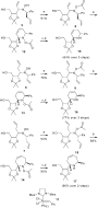
Scheme 3: Synthesis of piperidines 15–16 and azepine 17. Reagents and conditions: a) Ac2O, THF, 1 h, rt for 8...

Scheme 4: Synthesis of indolizidines 21–22 and pyrroloazepine 23. Reaction conditions: a) Tf2O, Py, rt, 2 h; ...
Synthesis of the Benzo- fused Indolizidine Alkaloid Mimics
- Daniel L. Comins and
- Kazuhiro Higuchi
Beilstein J. Org. Chem. 2007, 3, No. 42, doi:10.1186/1860-5397-3-42
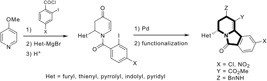
- -acyldihydropyridones 1a-c in good yields (entries 1–3). In addition, the N-methyl-2-indolyl [11] Grignard reagent gave 1d in moderate yield (entry 4). In spite of trying various methods of preparing the 2-pyridyl [12][13][14][15] Grignard reagent, 1e was obtained in only 15% yield (entry 5). Encouraged by these

Graphical Abstract

Figure 1: N-Acyldihydropyridone 1 and indolizidine alkaloids.

Scheme 1: Preparation of chloro-substituted compound 8j.

Scheme 2: Preparation of nitro-substituted compound 8k.

Scheme 3: α-Methoxycarbonylation of 11.

Scheme 4: Modification of functional groups within 8a.
A divergent asymmetric approach to aza-spiropyran derivative and (1S,8aR)-1-hydroxyindolizidine
- Jian-Feng Zheng,
- Wen Chen,
- Su-Yu Huang,
- Jian-Liang Ye and
- Pei-Qiang Huang
Beilstein J. Org. Chem. 2007, 3, No. 41, doi:10.1186/1860-5397-3-41
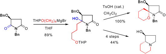
- the reaction of functionalized Grignard reagent with protected (S)-malimide, either aza-spiropyran or (1S,8aR)-1-hydroxyindolizidine skeleton could be constructed in a concise and selective manner. The results presented herein constitute an important extension of our malimide-based synthetic
- stereoselectively to either hydroxylactams F or G under appropriate conditions. [36][37][38] It was envisioned that if a C4-bifunctional Grignard reagent was used, both aza-spiroketal H (such as aza-spiropyran, n = 1, path a) and indolizidine ring systems I (path b) could be obtained. The synthesis of aza
- of the O-benzyl group in K is an assumption based on our previous observation on a similar case.[42] Conclusion In summary, we have demonstrated that by the reaction of functionalized Grignard reagent with the protected (S)-malimide 4, either aza-spiropyran derivative 7 or (1S,8aR)-1

Graphical Abstract

Scheme 1: The skeletons of useful aza-spiroketals and some naturally occurring hydroxylated indolizidines.
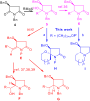
Scheme 2: Synthetic strategy based on N,O-dibenzylmalimide (4).

Scheme 3: Stereoselectivity synthesis of aza-spiropyran 7.

Figure 1: The observed NOE correlations (in part) and the region expanded NOESY spectrum of compound 7.

Scheme 4: Stereoselective synthesis of (1S,8aR)-1-hydroxyindolizidine (ent-3).

Scheme 5: One-pot synthesis of ent-3 from amino alcohol 8.
Development of potential manufacturing routes for substituted thiophenes – Preparation of halogenated 2-thiophenecarboxylic acid derivatives as building blocks for a new family of 2,6-dihaloaryl 1,2,4-triazole insecticides
- John W. Hull Jr.,
- Duane R. Romer,
- David E. Podhorez,
- Mezzie L. Ash and
- Christine H. Brady
Beilstein J. Org. Chem. 2007, 3, No. 23, doi:10.1186/1860-5397-3-23
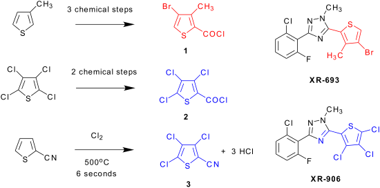
- -methylthiophene 11 in a 64% yield. [10] This reaction has also been reported using aqueous bromine. [11] The carboxyl functionality was then introduced by formation of the 2-thienyl Grignard reagent [8][9][10][11] followed by treatment with dimethylcarbonate (DMC) to give ester 12a. Alternatively, a palladium

Graphical Abstract

Figure 1: Thiophene structures 1, 2, and 3.

Figure 2: XR-693 and XR-906.

Scheme 1: Synthesis and Reactivity of 2,4,5-Tribromo-3-methylthiophene. Initial Bromination Approaches.

Scheme 2: Routes to 4-Bromo-3-methyl-2-thiopheneacid Chloride, 1, From 3-Methylthiophene, 4. (a) NBS/AcOH, 64...

Scheme 3: Vapor Phase Chlorination of 2-Thiophenecarbonitrile.

Scheme 4: Synthesis of 3,4,5-Trichloro-2-thiopheneacid Chloride, 2. (a) 1. n-BuLi/MTBE, -60°C, 2. CO2; or 1. ...

Scheme 5: Metal-Halogen Exchange in THF Solvent.
The use of silicon- based tethers for the Pauson- Khand reaction
- Adrian P. Dobbs,
- Ian J. Miller and
- Saša Martinović
Beilstein J. Org. Chem. 2007, 3, No. 21, doi:10.1186/1860-5397-3-21
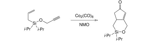
- procedure was developed, initially adding the allyl arm via the allyl Grignard reagent, followed by a more standard silyl ether formation using an acetylenic alcohol and imidazole (without isolating the intermediate silyl chloride). (Isolation of the intermediate diisopropylallylsilyl chloride was

Graphical Abstract

Scheme 1: Saigo's cycloisomerisation reaction under Pauson-Khand conditions.

Scheme 2: Pauson-Khand reaction and tether-cleavage in wet acetonitrile.

Scheme 3: Silyl-tethered allenic Pauson-Khand reaction reported by Brummond.

Scheme 4: Intramolecular Pauson-Khand reaction of allyldimethyl- and allyldiphenylsilyl propargyl ethers repo...

Scheme 5: Synthesis and attempted Pauson-Khand reactions of vinyldimethylsilyl- and vinyldiphenylsilyl ethers....

Figure 1: Functionalised acetylenes prepared and used in silyl ether-tethered Pauson-Khand reactions. Yields ...

Figure 2: Chain-functionalised acetylenes prepared and used in silyl ether-tethered Pauson-Khand reactions. Y...

Figure 3: Possible structure of THF-oxidation/insertion product.

Scheme 6: Model Pauson-Khand reaction of allyltrimethylsilane.

Scheme 7: Preparation of allyldiisopropylsilyl ethers.

Scheme 8: Pauson-Khand reaction of allyldiisopropylsilyl ethers.

Scheme 9: Preparation of allyldiisopropylsilanes.

Scheme 10: Attempted Mitsunobu reactions of diisopropylsilanols.

Scheme 11: Preparation of alkynic diisopropylsilanes.

Scheme 12: Preparation of allyldiisopropylsilyl ethers.

Scheme 13: Preparation of acetals from dichlorodiphenylsilane.

Scheme 14: Attempted Pauson-Khand reaction of allylpropargyldiphenylsilyl acetal.

Scheme 15: Proposed diisopropylsilyl acetal formation.

Scheme 16: Attempted allylpropargyldiisopropylsilyl acetal formation.

Scheme 17: Attempted allylpropargyldiisopropylsilyl acetal formation.

Scheme 18: Preparation of silicon-tethered Pauson-Khand precursors.

Scheme 19: Failed Pauson-Khand reaction of a silicon-tethered substrate.