Search results
Search for "homogeneous catalysts" in Full Text gives 48 result(s) in Beilstein Journal of Organic Chemistry.
Z-Selective semihydrogenation of alkynes via Ni/Lewis acid synergistic catalyzed system using DMF as hydrogen source and solvent
- Lei Kang,
- Haifeng Gao and
- Luo Yang
Beilstein J. Org. Chem. 2026, 22, 1004–1012, doi:10.3762/bjoc.22.79

- . outlined the state-of-the-art progress on stereoselective semihydrogenation of alkynes catalyzed by first-row (3d) transition metals, which attract substantial attention owing to their natural abundance and low toxicity [5]. In recent years, homogeneous catalysts based on Ni, Cu, Rh, and Co have shown

Graphical Abstract

Scheme 1: NiCl2/Zn(AcO)2·2H2O-co-catalyzed Z-selective semihydrogenation of internal alkynes to Z-internal al...

Scheme 2: NiCl2/Zn(AcO)2·2H2O-co-catalyzed semihydrogenation of terminal alkynes to terminal alkenes.

Scheme 3: NiCl2/Zn(AcO)2·2H2O-co-catalyzed semihydrogenation of alkylarylacetylene and dialkylacetylene to (Z...

Scheme 4: Control experiment using DMA as solvent together with exogenous formic acid instead of DMF.

Scheme 5: Proposed catalytic cycle for the Ni/Lewis acid-catalyzed semihydrogenation of alkynes with DMF.
C2 to C6 biobased carbonyl platforms for fine chemistry
- Jingjing Jiang,
- Muhammad Noman Haider Tariq,
- Florence Popowycz,
- Yanlong Gu and
- Yves Queneau
Beilstein J. Org. Chem. 2025, 21, 2103–2172, doi:10.3762/bjoc.21.165

- from homogeneous catalysts such as mineral acids, organic acids, metal salts (with high availability and low costs) to heterogeneous ones such as zeolites, metal oxides, sulfonated polymers, carbon-based solid acids. The latter allow to overcome the problems of separation encountered with homogeneous

Graphical Abstract

Figure 1: C2–C6 biobased carbonyl building blocks.

Scheme 1: Proposed (2 + 2) route to glycolaldehyde and glycolic acid from erythritol by Cu/AC catalyst (AC = ...

Scheme 2: Reductive amination of GCA.

Scheme 3: N-Formylation of secondary amines by reaction with GCA.

Scheme 4: Synthesis and conversion of hydroxy acetals to cyclic acetals.

Scheme 5: Synthesis of 3-(indol-3-yl)-2,3-dihydrofurans via three-component reaction of glycolaldehyde, indol...

Scheme 6: BiCl3-catalyzed synthesis of benzo[a]carbazoles from 2-arylindoles and α-bromoacetaldehyde ethylene...

Scheme 7: Cu/NCNSs-based conversion of glycerol to glycolic acid and other short biobased acids.

Scheme 8: E. coli-based biotransformation of C1 source molecules (CH4, CO2 and CO) towards C2 glycolic acid.

Scheme 9: N-Formylation of amines with C2 (a) or C3 (b) biomass-based feedstocks.

Scheme 10: Methods for the formation of propanoic acid (PA) from lactic acid (LA).

Scheme 11: Co-polymerization of biobased lactic acid and glycolic acid via a bicatalytic process.

Scheme 12: Oxidation of α-hydroxy acids by tetrachloroaurate(III) in acetic acid–sodium acetate buffer medium.

Figure 2: Selective catalytic pathways for the conversion of lactic acid (LA).

Scheme 13: Synthesis of 1,3-PDO via cross-aldol reaction between formaldehyde and acetaldehyde to 3-hydroxypro...

Scheme 14: Hydrothermal conversion of 1,3-dihydroxy-2-propane and 2,3-dihydroxypropanal to methylglyoxal.

Scheme 15: FLS-catalyzed formose reaction to synthesize GA and DHA.

Scheme 16: GCA and DHA oxidation products of glycerol and isomerization of GCA to DHA under flow conditions us...

Scheme 17: Acid-catalyzed reactions of DHA with alcohols.

Scheme 18: Synthesis of dihydroxyacetone phosphate from dihydroxyacetone.

Scheme 19: Bifunctional acid–base catalyst DHA conversion into lactic acid via pyruvaldehyde or fructose forma...

Scheme 20: Catalytic one-pot synthesis of GA and co-synthesis of formamides and formates from DHA.

Scheme 21: (a) Synthesis of furan derivatives and (b) synthesis of thiophene derivative by cascade [3 + 2] ann...

Scheme 22: Brønsted acidic ionic liquid catalyzed synthesis of benzo[a]carbazole from renewable acetol and 2-p...

Scheme 23: Asymmetric hydrogenation of α-hydroxy ketones to 1,2-diols.

Scheme 24: Synthesis of novel 6-(substituted benzylidene)-2-methylthiazolo [2,3-b]oxazol-5(6H)-one from 1-hydr...

Scheme 25: ʟ-Proline-catalyzed synthesis of anti-diols from hydroxyacetone and aldehydes.

Scheme 26: C–C-bond-formation reactions of a biomass-based feedstock aromatic aldehyde (C5) and hydroxyacetone...

Scheme 27: Ethanol upgrading to C4 bulk chemicals via the thiamine (VB1)-catalyzed acetoin condensation.

Scheme 28: One-pot sequential chemoenzymatic synthesis of 2-aminobutane-1,4-diol and 1,2,4-butanetriol via 1,4...

Scheme 29: Synthesis of 1,4-dihydroxybutan-2-one by microbial transformation.

Scheme 30: Conversion of polyols by [neocuproine)Pd(OAc)]2(OTf)2] to α-hydroxy ketones.

Scheme 31: Chemoselective oxidation of alcohols with chiral palladium-based catalyst 2.

Scheme 32: Electrochemical transformation of furfural to 5-hydroxy-2(5H)-furanone (HFO).

Scheme 33: Selective hydrodeoxygenation of HFO and oxidation to γ-butyrolactone (GBL).

Scheme 34: Photosensitized oxygenation of furan towards HFO via ozonide intermediates.

Scheme 35: Conversion of furfural to HFO and MAN by using mesoporous carbon nitride (SGCN) as photocatalyst.

Scheme 36: Synthesis of HFO from furan derivatives.

Scheme 37: Photooxidation of furfural to 5-hydroxy-2(5H)-furanone (HFO).

Scheme 38: Synthesis of Friedel–Crafts indole adduct from HFO.

Scheme 39: Conversion of HFO to α,γ-substituted chiral γ-lactones.

Scheme 40: Tautomeric transformation of HFO to formylacrylic acid.

Scheme 41: Hydrolysis of HFO to succinic acid in aqueous solution.

Scheme 42: Substitution and condensation reactions of 5-hydroxy-2(5H)-furanone (HFO).

Scheme 43: (a) Conversion of HFO towards valuable C4 chemicals and (b) anodic oxidation of 5-hydroxy-2(5H)-fur...

Figure 3: Conversion of HFO towards other natural and synthetic substances.

Scheme 44: Conversion of furfural to maleic anhydride (reaction a: VOx/Al2O3; reaction b: VPO).

Scheme 45: Conversion of furfural into succinic acid.

Scheme 46: Electro‑, photo‑, and biocatalysis for one-pot selective conversions of furfural into C4 chemicals.

Scheme 47: Production route of furfural from hemicellulose.

Scheme 48: Mechanism for xylose dehydration to furfural through a choline xyloside intermediate.

Scheme 49: Conversion of furfural to furfuryl alcohol and its derivatives.

Scheme 50: Conversion of furfural to furfuryl alcohol and 3-(2-furyl)acrolein.

Scheme 51: The aerobic oxidative condensation of biomass-derived furfural and linear alcohols.

Scheme 52: The single-step synthesis of 2-pentanone from furfural.

Scheme 53: Electrocatalytic coupling reaction of furfural and levulinic acid.

Scheme 54: Conversion of furfural to m-xylylenediamine.

Scheme 55: Conversion of furfural to tetrahydrofuran-derived amines.

Scheme 56: Formation of trans-4,5-diamino-cyclopent-2-enones from furfural.

Scheme 57: Production of pyrrole and proline from furfural.

Scheme 58: Synthesis of 1‑(trifluoromethyl)-8-oxabicyclo[3.2.1]oct-3-en-2-ones from furfural.

Scheme 59: Conversion of furfural to furfural-derived diacids.

Scheme 60: A telescope protocol derived from furfural and glycerol.

Scheme 61: A tandem cyclization of furfural and 5,5-dimethyl-1,3-cyclohexanedione.

Scheme 62: A Ugi four-component reaction to construct furfural-based polyamides.

Scheme 63: One-pot synthesis of γ-acyloxy-Cy7 from furfural.

Scheme 64: Dimerization–Piancatelli sequence toward humins precursors from furfural.

Scheme 65: Conversion of furfural to CPN.

Scheme 66: Synthesis of jet fuels range cycloalkanes from CPN and lignin-derived vanillin.

Scheme 67: Solar-energy-driven synthesis of high-density biofuels from CPN.

Scheme 68: Reductive amination of CPN to cyclopentylamine.

Scheme 69: Asymmetric hydrogenation of C=O bonds of exocyclic α,β-unsaturated cyclopentanones.

Scheme 70: Preparation of levulinic acid via the C5 route (route a) or C6 route (routes b1 and b2).

Scheme 71: Mechanism of the rehydration of HMF to levulinic acid and formic acid.

Scheme 72: Important levulinic acid-derived chemicals.

Scheme 73: Direct conversion of levulinic acid to pentanoic acid.

Scheme 74: Catalytic aerobic oxidation of levulinic acid to citramalic acid.

Scheme 75: Conversion of levulinic acid to 1,4-pentanediol (a) see ref. [236]; b) see ref. [237]; c) see ref. [238]; d) see r...

Scheme 76: Selective production of 2-butanol through hydrogenolysis of levulinic acid.

Scheme 77: General reaction pathways proposed for the formation of 5MPs from levulinic acid.

Scheme 78: Selective reductive amination of levulinic acid to N-substituted pyrroles.

Scheme 79: Reductive amination of levulinic acid to chiral pyrrolidinone.

Scheme 80: Reductive amination of levulinic acid to non-natural chiral γ-amino acid.

Scheme 81: Nitrogen-containing chemicals derived from levulinic acid.

Scheme 82: Preparation of GVL from levulinic acid by dehydration and hydrogenation.

Scheme 83: Ruthenium-catalyzed levulinic acid to chiral γ-valerolactone.

Scheme 84: Catalytic asymmetric hydrogenation of levulinic acid to chiral GVL.

Scheme 85: Three steps synthesis of ε-caprolactam from GVL.

Scheme 86: Multistep synthesis of nylon 6,6 from GVL.

Scheme 87: Preparation of MeGVL by α-alkylation of GVL.

Scheme 88: Ring-opening polymerization of five-membered lactones.

Scheme 89: Synthesis of GVL-based ionic liquids.

Scheme 90: Preparation of butene isomers from GVL under Lewis acid conditions.

Scheme 91: Construction of C5–C12 fuels from GVL over nano-HZSM-5 catalysts.

Scheme 92: Preparation of alkyl valerate from GVL via ring opening/reduction/esterification sequence.

Scheme 93: Construction of 4-acyloxypentanoic acids from GVL.

Scheme 94: Synthesis of 1,4-pentanediol (PDO) from GVL.

Scheme 95: Construction of novel cyclic hemiketal platforms via self-Claisen condensation of GVL.

Scheme 96: Copper-catalyzed lactamization of GVL.

Figure 4: Main scaffolds obtained from HMF.

Scheme 97: Biginelli reactions towards HMF-containing dihydropyrimidinones.

Scheme 98: Hantzsch dihydropyridine synthesis involving HMF.

Scheme 99: The Kabachnik–Fields reaction involving HMF.

Scheme 100: Construction of oxazolidinone from HMF.

Scheme 101: Construction of rhodamine-furan hybrids from HMF.

Scheme 102: A Groebke–Blackburn–Bienaymé reaction involving HMF.

Scheme 103: HMF-containing benzodiazepines by [4 + 2 + 1] cycloadditions.

Scheme 104: Synthesis of fluorinated analogues of α-aryl ketones.

Scheme 105: Synthesis of HMF derived disubstituted γ-butyrolactone.

Scheme 106: Functionalized aromatics from furfural and HMF.

Scheme 107: Diels–Alder adducts from HMF or furfural with N-methylmaleimide.

Scheme 108: Pathway of the one-pot conversion of HMF into phthalic anhydride.

Scheme 109: Photocatalyzed preparation of humins (L-H) from HMF mixed with spoiled HMF residues (LMW-H) and fur...

Scheme 110: Asymmetric dipolar cycloadditions on HMF.

Scheme 111: Dipolar cycloadditions of HMF based nitrones to 3,4- and 3,5-substituted isoxazolidines.

Scheme 112: Production of δ-lactone-fused cyclopenten-2-ones from HMF.

Scheme 113: Aza-Piancatelli access to aza-spirocycles from HMF-derived intermediates.

Scheme 114: Cross-condensation of furfural, acetone and HMF into C13, C14 and C15 products.

Scheme 115: Base-catalyzed aldol condensation/dehydration sequences from HMF.

Scheme 116: Condensation of HMF and active methylene nitrile.

Scheme 117: MBH reactions involving HMF.

Scheme 118: Synthesis of HMF-derived ionic liquids.

Scheme 119: Reductive amination/enzymatic acylation sequence towards HMF-based surfactants.

Scheme 120: The formation of 5-chloromethylfurfural (CMF).

Scheme 121: Conversion of CMF to HMF, levulinic acid, and alkyl levulinates.

Scheme 122: Conversion of CMF to CMFCC and FDCC.

Scheme 123: Conversion of CMF to BHMF.

Scheme 124: Conversion of CMF to DMF.

Scheme 125: CMF chlorine atom substitutions toward HMF ethers and esters.

Scheme 126: Introduction of carbon nucleophiles in CMF.

Scheme 127: NHC-catalyzed remote enantioselective Mannich-type reactions of CMF.

Scheme 128: Conversion of CMF to promising biomass-derived dyes.

Scheme 129: Radical transformation of CMF with styrenes.

Scheme 130: Synthesis of natural herbicide δ-aminolevulinic acid from CMF.

Scheme 131: Four step synthesis of the drug ranitidine from CMF.

Scheme 132: Pd/CO2 cooperative catalysis for the production of HHD and HXD.

Scheme 133: Different ruthenium (Ru) catalysts for the ring-opening of 5-HMF to HHD.

Scheme 134: Proposed pathways for preparing HXD from HMF.

Scheme 135: MCP formation and uses.

Scheme 136: Cu(I)-catalyzed highly selective oxidation of HHD to 2,5-dioxohexanal.

Scheme 137: Synthesis of N‑substituted 3‑hydroxypyridinium salts from 2,5-dioxohexanal.

Scheme 138: Ru catalyzed hydrogenations of HHD to 1,2,5-hexanetriol (a) see ref. [396]; b) see ref. [397]).

Scheme 139: Aviation fuel range quadricyclanes produced by HXD.

Scheme 140: Synthesis of HDGK from HXD and glycerol as a chain extender.

Scheme 141: Synthesis of serinol pyrrole from HXD and serinol.

Scheme 142: Synthesis of pyrroles from HXD and nitroarenes.

Scheme 143: Two-step production of PX from cellulose via HXD.

Scheme 144: Preparation of HCPN from HMF via hydrogenation and ring rearrangement.

Scheme 145: Suggested pathways from HMF to HCPN.

Scheme 146: α-Alkylation of HCPN with ethylene gas.

Scheme 147: Synthesis of 3-(hydroxymethyl)cyclopentylamine from HMF via reductive amination of HCPN.

Scheme 148: Production of LGO and Cyrene® from biomass.

Scheme 149: Synthesis of HBO from LGO and other applications.

Scheme 150: Construction of m-Cyrene® homopolymer.

Scheme 151: Conversion of Cyrene® to THFDM and 1,6-hexanediol.

Scheme 152: RAFT co-polymerization of LGO and butadienes.

Scheme 153: Polycondensation of HO-LGOL and diols with dimethyl adipate.

Scheme 154: Self-condensation of Cyrene® and Claisen–Schmidt reactions.

Scheme 155: Synthesis of 5-amino-2-(hydroxymethyl)tetrahydropyran from Cyrene®.
Catalysing (organo-)catalysis: Trends in the application of machine learning to enantioselective organocatalysis
- Stefan P. Schmid,
- Leon Schlosser,
- Frank Glorius and
- Kjell Jorner
Beilstein J. Org. Chem. 2024, 20, 2280–2304, doi:10.3762/bjoc.20.196

- . Keywords: catalyst design; machine learning; modelling; organocatalysis; selectivity prediction; Introduction Since the beginning of the 21st century, organocatalysts [1] have established themselves as a third group of homogeneous catalysts, next to biocatalysts [2] (enzymes) and transition metal-based

Graphical Abstract

Figure 1: Schematic depiction of available data sources for predictive modelling, each with its advantages an...

Figure 2: Schematic depiction of different kinds of molecular representations for fluoronitroethane. Among th...

Figure 3: Depiction of the energy diagram of a generic enantioselective reaction. In the centre, catalyst and...

Figure 4: Hammett parameters are derived from the equilibrium constant of substituted benzoic acids (example ...

Figure 5: Selected examples of popular descriptors applied to model organocatalytic reactions. Descriptors en...

Figure 6: Example bromocyclization reaction from Toste and co-workers using a DABCOnium catalyst system and C...

Figure 7: Example from Neel et al. using a chiral ion pair catalyst for the selective fluorination of allylic...

Figure 8: Data set created by Denmark and co-workers for the CPA-catalysed thiol addition to N-acylimines [67]. T...

Figure 9: Selected examples of ML developments that used the dataset from Denmark and co-workers [67]. (A) Varnek...

Figure 10: Study from Reid and Sigman developing statistical models for CPA-catalysed nucleophilic addition re...

Figure 11: Selected examples of studies where mechanistic transferability was exploited to model multiple reac...

Figure 12: Generality approach by Denmark and co-workers [132] for the iodination of arylpyridines. From the releva...

Figure 13: Betinol et al. [133] clustered the relevant chemical space and then evaluated the average ee for every c...

Figure 14: Corminboeuf and co-workers [134] chose a representative subset of the reaction space (indicated by dark ...

Figure 15: Example for data-driven modelling to improve substrate and catalyst design. (A) C–N coupling cataly...

Figure 16: Example for utilising a genetic algorithm for catalyst design. (A) Morita–Baylis–Hillman reaction s...

Figure 17: Organocatalysed synthesis of spirooxindole analogues by Kondo et al. [171] (A) Reaction scheme of dienon...

Figure 18: Schematic depiction of required developments in order to overcome current limitations of ML for org...
Factors influencing the performance of organocatalysts immobilised on solid supports: A review
- Zsuzsanna Fehér,
- Dóra Richter,
- Gyula Dargó and
- József Kupai
Beilstein J. Org. Chem. 2024, 20, 2129–2142, doi:10.3762/bjoc.20.183

- fine chemical and pharmaceutical industries [9]. The limitation of homogeneous catalysts, however, is their complex, time-consuming and energy-intensive recovery and subsequent recycling. Therefore, synthetic modification of catalysts is a commonly used method to aid their recovery. Obstacles to the
- recycling of homogeneous catalysts can be addressed by heterogenisation of homogeneous catalysts [10], either following their application as homogeneous catalysts or before their application (heterogeneous catalysis). In heterogeneous catalysis, catalysts and reactants are present in different phases

Graphical Abstract

Scheme 1: Esterification of oleic acid (1) with propylsulfonic acid (Pr-SO3H)-functionalised mesoporous silic...

Scheme 2: Using confinement of organocatalytic units for improving the enantioselectivity of silica-supported...

Scheme 3: Michael addition catalysed by cinchona thiourea immobilised on magnetic nanoparticles (13).

Scheme 4: Michael addition catalysed by cinchona thiourea in the presence of magnetic nanoparticles.

Scheme 5: Benzoin condensation catalysed by N-benzylthiazolium salt attached to mesoporous material.

Scheme 6: Photoinduced RAFT polymerisation of n-butyl acrylate (19) catalysed by silica nanoparticle-supporte...

Scheme 7: Pressure and temperature dependence of the 1,4-addition of propanal to trans-β-nitrostyrene under c...

Scheme 8: α-Amination of ethyl 2-oxocyclopentanecarboxylate catalysed by PS-THU which could be recycled over ...

Scheme 9: Preparation of supported catalysts C29–C31 from cinchona squaramides 29–31 modified with a primary ...

Scheme 10: Application of PGMA-supported organocatalysts C29–C31 in the asymmetric Michael addition of pentane...

Scheme 11: Alcoholytic desymmetrisation of a cyclic anhydride 34 catalysed by polyamide-supported cinchona sul...
Manganese-catalyzed C–C and C–N bond formation with alcohols via borrowing hydrogen or hydrogen auto-transfer
- Mohd Farhan Ansari,
- Atul Kumar Maurya,
- Abhishek Kumar and
- Saravanakumar Elangovan
Beilstein J. Org. Chem. 2024, 20, 1111–1166, doi:10.3762/bjoc.20.98

- , expensive, and limited in availability. Hence, replacing them with the first row of transition metals would increase the sustainability and profitability of this procedure [13]. Indeed, many 3d-metal-based homogeneous catalysts have been documented for BH reactions [14][15] since these metals are
- homogeneous catalysts, including noble and non-noble metals, have been studied for the alkylation of ketones with primary and secondary alcohols [55][56]. In this section, we discuss the development of manganese complexes (Figure 2) for coupling primary and secondary alcohols with ketones to give the

Graphical Abstract

Scheme 1: General scheme of the borrowing hydrogen (BH) or hydrogen auto-transfer (HA) methodology.

Scheme 2: General scheme for C–N bond formation. A) Traditional cross-couplings with alkyl or aryl halides. B...

Figure 1: Manganese pre-catalysts used for the N-alkylation of amines with alcohols.

Scheme 3: Manganese(I)-pincer complex Mn1 used for the N-alkylation of amines with alcohols and methanol.

Scheme 4: N-Methylation of amines with methanol using Mn2.

Scheme 5: C–N-Bond formation with amines and methanol using PN3P-Mn complex Mn3 reported by Sortais et al. [36]. a...

Scheme 6: Base-assisted synthesis of amines and imines with Mn4. Reaction assisted by A) t-BuOK and B) t-BuON...

Scheme 7: Coupling of alcohols and hydrazine via the HB approach reported by Milstein et al. [38]. aReaction time...

Scheme 8: Proposed mechanism for the coupling of alcohols and hydrazine catalyzed by Mn5.

Scheme 9: Phosphine-free manganese catalyst for N-alkylation of amines with alcohols reported by Balaraman an...

Scheme 10: N-Alkylation of sulfonamides with alcohols.

Scheme 11: Mn–NHC catalyst Mn6 applied for the N-alkylation of amines with alcohols. a3 mol % of Mn6 were used....

Scheme 12: N-Alkylation of amines with primary and secondary alcohols. a80 °C, b100 °C.

Scheme 13: Manganese(III)-porphyrin catalyst for synthesis of tertiary amines.

Scheme 14: Proposed mechanism for the alcohol dehydrogenation with Mn(III)-porphyrin complex Mn7.

Scheme 15: N-Methylation of nitroarenes with methanol using catalyst Mn3.

Scheme 16: Mechanism of manganese-catalyzed methylation of nitroarenes using Mn3 as the catalyst.

Scheme 17: Bidentate manganese complex Mn8 applied for the N-alkylation of primary anilines with alcohols. aOn...

Scheme 18: N-Alkylation of amines with alcohols in the presence of manganese salts and triphenylphosphine as t...

Scheme 19: N-Alkylation of diazo compounds with alcohols using catalyst Mn9.

Scheme 20: Proposed mechanism for the amination of alcohols with diazo compounds catalyzed by catalyst Mn9.

Scheme 21: Mn1 complex-catalyzed synthesis of polyethyleneimine from ethylene glycol and ethylenediamine.

Scheme 22: Bis-triazolylidene-manganese complex Mn10 for the N-alkylation of amines with alcohols.

Figure 2: Manganese complexes applied for C-alkylation reactions of ketones with alcohols.

Scheme 23: General scheme for the C–C bond formation with alcohols and ketones.

Scheme 24: Mn1 complex-catalyzed α-alkylation of ketones with primary alcohols.

Scheme 25: Mechanism for the Mn1-catalyzed alkylation of ketones with alcohols.

Scheme 26: Phosphine-free in situ-generated manganese catalyst for the α-alkylation of ketones with primary al...

Scheme 27: Plausible mechanism for the Mn-catalyzed α-alkylation of ketones with alcohols.

Scheme 28: α-Alkylation of esters, ketones, and amides using alcohols catalyzed by Mn11.

Scheme 29: Mono- and dialkylation of methylene ketones with primary alcohols using the Mn(acac)2/1,10-phenanth...

Scheme 30: Methylation of ketones with methanol and deuterated methanol.

Scheme 31: Methylation of ketones and esters with methanol. a50 mol % of t-BuOK were used, bCD3OD was used ins...

Scheme 32: Alkylation of ketones and secondary alcohols with primary alcohols using Mn4.

Scheme 33: Bidentate manganese-NHC complex Mn6 applied for the synthesis of alkylated ketones using alcohols.

Scheme 34: Mn1-catalyzed synthesis of substituted cycloalkanes by coupling diols and secondary alcohols or ket...

Scheme 35: Proposed mechanism for the synthesis of cycloalkanes via BH method.

Scheme 36: Synthesis of various cycloalkanes from methyl ketones and diols catalyze by Mn13. aReaction time wa...

Scheme 37: N,N-Amine–manganese complex (Mn13)-catalyzed alkylation of ketones with alcohols.

Scheme 38: Naphthyridine‑N‑oxide manganese complex Mn14 applied for the alkylation of ketones with alcohols. a...

Scheme 39: Proposed mechanism of the naphthyridine‑N‑oxide manganese complex (Mn14)-catalyzed alkylation of ke...

Scheme 40: α-Methylation of ketones and indoles with methanol using Mn15.

Scheme 41: α-Alkylation of ketones with primary alcohols using Mn16. aNMR yield.

Figure 3: Manganese complexes used for coupling of secondary and primary alcohols.

Scheme 42: Alkylation of secondary alcohols with primary alcohols catalyzed by phosphine-free catalyst Mn17. a...

Scheme 43: PNN-Manganese complex Mn18 for the alkylation of secondary alcohols with primary alcohols.

Scheme 44: Mechanism for the Mn-pincer catalyzed C-alkylation of secondary alcohols with primary alcohols.

Scheme 45: Upgrading of ethanol with methanol for isobutanol production.

Scheme 46: Mn-Pincer catalyst Mn19 applied for the β-methylation of alcohols with methanol. a2.0 mol % of Mn19...

Scheme 47: Functionalized ketones from primary and secondary alcohols catalyzed by Mn20. aMn20 (5 mol %), NaOH...

Scheme 48: Synthesis of γ-disubstituted alcohols and β-disubstituted ketones through Mn9-catalyzed coupling of...

Scheme 49: Proposed mechanism for the Mn9-catalyzed synthesis of γ-disubstituted alcohols and β-disubstituted ...

Scheme 50: Dehydrogenative coupling of ethylene glycol and primary alcohols catalyzed by Mn4.

Scheme 51: Mn18-cataylzed C-alkylation of unactivated esters and amides with alcohols.

Scheme 52: Alkylation of amides and esters using Mn21.

Scheme 53: α-Alkylation of nitriles with primary alcohols using in situ-generated manganese catalyst.

Scheme 54: Proposed mechanism for the α-alkylation of nitriles with primary alcohols.

Scheme 55: Mn9-catalyzed α-alkylation of nitriles with primary alcohols. a1,4-Dioxane was used as solvent, 24 ...

Figure 4: Manganese complexes used for alkylation of heterocyclic compounds.

Scheme 56: Aminomethylation of aromatic compounds with secondary amines and methanol catalyzed by Mn22.

Scheme 57: Regioselective alkylation of indolines with alcohols catalyzed by Mn9. aMn9 (4 mol %), 48 h.

Scheme 58: Proposed mechanism for the C- and N-alkylation of indolines with alcohols.

Scheme 59: C-Alkylation of methyl N-heteroarenes with primary alcohols catalyzed by Mn1. aTime was 60 h.

Scheme 60: C-Alkylation of oxindoles with secondary alcohols.

Scheme 61: Plausible mechanism for the Mn23-catalyzed C-alkylation of oxindoles with secondary alcohols.

Scheme 62: Synthesis of C-3-alkylated products by coupling alcohols with indoles and aminoalcohols.

Scheme 63: C3-Alkylation of indoles using Mn1.

Scheme 64: C-Methylation of indoles with Mn15 and methanol.

Scheme 65: α-Alkylation of 2-oxindoles with primary and secondary alcohols catalyzed by Mn25. aReaction carrie...

Scheme 66: Dehydrogenative alkylation of indolines with Mn1. aMn1 (5.0 mol %) was used.

Scheme 67: Synthesis of bis(indolyl)methane derivatives from indoles and alcohols catalyzed by Mn26. aMn26 (5....

Scheme 68: One-pot synthesis of pyrimidines via BH.

Scheme 69: Synthesis of pyrroles from alcohols and aminoalcohols using Mn4.

Scheme 70: Synthesis of pyrroles via multicomponent reaction catalyzed by Mn12.

Scheme 71: Friedländer quinoline synthesis using an in situ-generated phosphine-free manganese catalyst.

Scheme 72: Quinoline synthesis using bis-N-heterocyclic carbene-manganese catalyst Mn6.

Scheme 73: Quinoline synthesis using manganese(III)-porphyrin catalyst Mn7.

Scheme 74: Manganese-catalyzed tetrahydroquinoline synthesis via borrowing BH.

Scheme 75: Proposed mechanism for the manganese-catalyzed tetrahydroquinoline synthesis.

Scheme 76: Synthesis of C3-alkylated indoles using Mn24.

Scheme 77: Synthesis of C-3-alkylated indoles using Mn1.

Scheme 78: C–C Bond formation by coupling of alcohols and ylides.

Scheme 79: C-Alkylation of fluorene with alcohols catalyzed by Mn24.

Scheme 80: Proposed mechanism for the C-alkylation of fluorene with alcohols catalyzed by Mn24.

Scheme 81: α-Alkylation of sulfones using Mn-PNN catalyst Mn28.
A novel recyclable organocatalyst for the gram-scale enantioselective synthesis of (S)-baclofen
- Gyula Dargó,
- Dóra Erdélyi,
- Balázs Molnár,
- Péter Kisszékelyi,
- Zsófia Garádi and
- József Kupai
Beilstein J. Org. Chem. 2023, 19, 1811–1824, doi:10.3762/bjoc.19.133

- addition of trans-β-nitrostyrene (12) and acetylacetone (13). Choosing the best solvent for the reaction is crucial, thus, solubility tests were carried out (Table 1). Since homogeneous catalysts usually exhibit higher activity and selectivity than their heterogeneous counterparts [27], our aim was to

Graphical Abstract

Figure 1: Application of cinchona squaramide 1 and recyclable, lipophilic cinchona squaramide organocatalysts ...

Scheme 1: Synthesis of demethylated cinchona squaramide organocatalyst and the incorporation of the flexible ...

Scheme 2: Synthesis of the lipophilic tag from methyl gallate (8) and attachment to the cinchona squaramide.

Figure 2: Classification of the tested non-polar solvents according to the GSK’s solvent sustainability guide ...

Figure 3: Recycling of the lipophilic organocatalyst in the stereoselective Michael addition by replacing the...

Scheme 3: A new, stereoselective synthetic route for baclofen.

Scheme 4: Gram-scale synthesis of (S)-baclofen hydrochloride.
Inline purification in continuous flow synthesis – opportunities and challenges
- Jorge García-Lacuna and
- Marcus Baumann
Beilstein J. Org. Chem. 2022, 18, 1720–1740, doi:10.3762/bjoc.18.182

- solution to avoid particles in the chromatography system [37][124]. In relation to nanofiltration, several devices equipped with specific membranes have been reported. Hessel and co-workers published a detailed review about inline recycling and separation of homogeneous catalysts, which contains a detailed

Graphical Abstract

Scheme 1: Automated in-line chromatography with the Advion puriFlash® system. The rightmost part of the schem...

Scheme 2: Purification via pH tuning and several Zaiput membranes. Redrawn from [51].

Scheme 3: Two-phase recirculating system for purifications of an immobilized enzyme-based reaction. Redrawn f...

Scheme 4: Countercurrent L–L purification using large Zaiput membranes in the presence of a phase transfer ca...

Scheme 5: General scheme of a telescoped flow process using L–L separators.

Scheme 6: Example of phase separation using a computer-vision approach. Redrawn from [68].

Scheme 7: Example of an inline purification using heterogeneous scavenging. Redrawn from [76].

Scheme 8: General scheme of a telescoped process using heterogenous cartridges.

Scheme 9: Comparison of two strategies for flow-based imatinib syntheses. Redrawn from [91] and [92].

Scheme 10: General purification scheme using the catch and release strategy.

Scheme 11: Exemplar catch and release purification of a stereoselective oxidation. Redrawn from [105].

Scheme 12: Catch and release-type purification using conventional SiO2. Redrawn from [107].

Scheme 13: Schematic representation of an industrial continuous crystallization. Redrawn from [109].

Scheme 14: General scheme of an academic inline crystallization approach.

Scheme 15: Simplified overview of purification options and selected criteria.
A resorcin[4]arene hexameric capsule as a supramolecular catalyst in elimination and isomerization reactions
- Tommaso Lorenzetto,
- Fabrizio Fabris and
- Alessandro Scarso
Beilstein J. Org. Chem. 2022, 18, 337–349, doi:10.3762/bjoc.18.38

- the cyclization of citronellal have been developed mostly based on transition metals, both as heterogeneous and homogeneous catalysts frequently under much harsher experimental conditions [48][49][50]. The same cyclization of citronellal was reported also by Raymond and collaborators in water using a

Graphical Abstract

Scheme 1: Resorcin[4]arene 1 forming the corresponding hexameric capsule 16 and the species used for control ...

Scheme 2: Carbonyl–ene intramolecular cyclization of (S)-citronellal to the corresponding diastereoisomeric c...

Figure 1: 1H NMR spectra in water-saturated CDCl3 except for G. A: [16] (7.5 mM); B: citronellal; C: citronel...

Scheme 3: Dehydration reaction of 1,1-diphenylethanol to 1,1-diphenylethylene.

Figure 2: 1H NMR spectra in water-saturated CDCl3 except for G. A: [16] (7.5 mM); B: 1,1-diphenylethanol; C: ...

Scheme 4: Possible isomerization products from β-pinene and α-pinene.

Figure 3: 1H NMR spectra in water-saturated CDCl3 except for G. A: [16] (7.5 mM); B: α-pinene; C: α-pinene (7...

Figure 4: 1H NMR spectra in water-saturated CDCl3 except for G. A: [16] (7.5 mM); B: β-pinene; C: β-pinene (7...

Figure 5: 1H NMR spectra in water-saturated CDCl3, except for E. A: [16] (7.5 mM); B: β-pinene; C: β-pinene (...
Green synthesis of C5–C6-unsubstituted 1,4-DHP scaffolds using an efficient Ni–chitosan nanocatalyst under ultrasonic conditions
- Soumyadip Basu,
- Sauvik Chatterjee,
- Suman Ray,
- Suvendu Maity,
- Prasanta Ghosh,
- Asim Bhaumik and
- Chhanda Mukhopadhyay
Beilstein J. Org. Chem. 2022, 18, 133–142, doi:10.3762/bjoc.18.14

- yield, the use of an eco-friendly solvent and a recyclable nanocatalyst, as well as reaction at room temperature. Keywords: 1,4-DHPs; green synthesis; magnetically recyclable catalyst; Ni–chitosan nanoparticles; ultrasonication; Introduction Homogeneous catalysts, despite having an outstanding

Graphical Abstract

Figure 1: FTIR spectra of (a) the Ni–chitosan NPs and (b) bare chitosan.

Figure 2: PXRD data for the Ni–chitosan NPs.

Figure 3: TEM (a and b) and SEM images (c and d) of the Ni–chitosan NPs.

Figure 4: EDX spectrum of the Ni–chitosan NPs.

Figure 5: Synthesis of dialkyl 1,4-dihydropyridine-2,3-dicarboxylate derivatives.

Figure 6: ORTEP representation of product 4a (CCDC 1949329).

Scheme 1: A plausible mechanistic route for the synthesis of C5–C6-unsubstituted 1,4-DHP derivatives using th...

Figure 7: Recycling experiment of the Ni–chitosan nanocatalyst.
Recent advances and perspectives in ruthenium-catalyzed cyanation reactions
- Thaipparambil Aneeja,
- Cheriya Mukkolakkal Abdulla Afsina,
- Padinjare Veetil Saranya and
- Gopinathan Anilkumar
Beilstein J. Org. Chem. 2022, 18, 37–52, doi:10.3762/bjoc.18.4

- -aryl-substituted cyclic tertiary amines including N-arylpiperidines and N-aryltetrahydroisoquinolines. The high reusability of the catalyst at least seven times further enhanced the importance of this strategy in the field of organic synthesis. 1.2 Cyanation of amines using homogeneous catalysts An

Graphical Abstract

Scheme 1: Starch-immobilized ruthenium trichloride-catalyzed cyanation of tertiary amines.

Scheme 2: Proposed mechanism for the cyanation of tertiary amines using starch-immobilized ruthenium trichlor...

Scheme 3: Cyanation of tertiary amines using heterogeneous Ru/C catalyst.

Scheme 4: Proposed mechanism for cyanation of tertiary amines using a heterogeneous Ru/C catalyst.

Scheme 5: Ruthenium-carbamato complex-catalyzed oxidative cyanation of tertiary amines.

Scheme 6: Cyanation of tertiary amines using immobilized MCM-41-2N-RuCl3 as the catalyst.

Scheme 7: Cyanation of tertiary amines using RuCl3·nH2O as the catalyst and molecular oxygen as oxidant.

Scheme 8: RuCl3-catalyzed cyanation of tertiary amines using NaCN/HCN and H2O2 as oxidant.

Scheme 9: Proposed mechanism for the ruthenium-catalyzed oxidative cyanation using H2O2.

Scheme 10: Proposed mechanism for the ruthenium-catalyzed aerobic oxidative cyanation.

Scheme 11: RuCl3-catalyzed oxidative cyanation of tertiary amines using acetone cyanohydrin as the cyanating a...

Scheme 12: Cyanation of indoles using K4[Fe(CN)6] as cyano source and Ru(III)-exchanged NaY zeolite (RuY) as c...

Scheme 13: Cyanation of arenes and heteroarenes using a ruthenium(II) catalyst and N-cyano-N-phenyl-p-toluenes...

Scheme 14: Proposed mechanism for the cyanation of arenes and heteroarenes using ruthenium(II) as catalyst and...

Scheme 15: Synthesis of N-(2-cyanoaryl)-7-azaindoles.

Figure 1: Structure of the TiO2-immobilized ruthenium polyazine complex.

Scheme 16: Visible-light-induced oxidative cyanation of aza-Baylis–Hillman adducts.

Scheme 17: Synthesis of 1° alkyl nitriles using [Ru(bpy)3](PF6)2 as the photocatalyst.

Scheme 18: Synthesis of 2° and 3° alkyl nitriles using [Ru(bpy)3](PF6)2 as the photocatalyst.

Scheme 19: Photoredox cross coupling reaction.

Scheme 20: Synthesis of α-amino nitriles from amines via a one-pot strategy.

Scheme 21: Proposed mechanistic pathway for the cyanation of the aldimine intermediate.

Scheme 22: Strecker-type functionalization of N-aryl-substituted tetrahydroisoquinolines under flow conditions....

Scheme 23: One-pot synthesis of α-aminonitriles using RuCl3 as catalyst.

Scheme 24: Synthesis of alkyl nitriles using (Ru(TMHD)3) as the catalyst.

Scheme 25: Synthesis of cyanated isoxazolines from alkenyl oximes catalyzed by [RuCl2(p-cymene)]2 in the prese...

Scheme 26: Proposed mechanism for the synthesis of cyanated isoxazolines from alkenyl oximes.

Scheme 27: Oxidative cyanation of differently substituted alcohols.
[2 + 1] Cycloaddition reactions of fullerene C60 based on diazo compounds
- Yuliya N. Biglova
Beilstein J. Org. Chem. 2021, 17, 630–670, doi:10.3762/bjoc.17.55

- pincer ligands 57, 58 [102], 59 [103], and 60 [104], or the so-called “bucky ligands” (Scheme 18). In the development of new organometallic C60 compounds that can be used as homogeneous catalysts, new blocks 61 and 62, cross-conjugated through cyclopropane, were synthesized (Scheme 19) [104]. Attaching
Valorisation of plastic waste via metal-catalysed depolymerisation
- Francesca Liguori,
- Carmen Moreno-Marrodán and
- Pierluigi Barbaro
Beilstein J. Org. Chem. 2021, 17, 589–621, doi:10.3762/bjoc.17.53

- catalyst replacements for zinc acetate in the glycolysis of PET are examples of this direction [129][130]. Recent studies focused on molecular complexes as homogeneous catalysts, whereas heterogeneous systems based on solid-supported metal nanoparticles (NPs) have been scarcely investigated. 3.1
- mediated by commercially available Ru homogeneous catalysts [148]. The process afforded C16 to C44 mixtures of macrocyclic oligobutadienes with up to 98% selectivity at moderate conversions (59–88%) using first-generation Ru complexes bearing a tricyclohexylphosphine (PCy3) ligand, mild reaction
- and the possible product contamination by homogeneous catalysts [199]. The conventional catalysts for this reaction are EG-soluble metal acetates, the activity of which showed a decrease in the order Zn2+ > Mn2+ > Co2+, which was attributed to the diverse interaction between the metal cation promoter

Graphical Abstract

Figure 1: Potential classification of plastic recycling processes. The area covered by the present review is ...

Figure 2: EG produced during glycolytic depolymerisation of PET using DEG + DPG as solvent and titanium(IV) n...

Scheme 1: Simplified representation of the conversion of 1,4-PBD to C16–C44 macrocycles using Ru metathesis c...

Figure 3: Main added-value monomers obtainable by catalytic depolymerisation of PET via chemolytic methods.

Scheme 2: Hydrogenolytic depolymerisation of PET by ruthenium complexes.

Scheme 3: Depolymerisation of PET via catalytic hydrosilylation by Ir(III) pincer complex.

Scheme 4: Catalytic hydrolysis (top) and methanolysis (bottom) reactions of PET.

Scheme 5: Depolymerisation of PET by glycolysis with ethylene glycol.

Figure 4: Glycolysis of PET: evolution of BHET yield over time, with and without zinc acetate catalyst (196 °...

Scheme 6: Potential activated complex for the glycolysis reaction of PET catalysed by metallated ILs and evol...

Scheme 7: One-pot, two-step process for PET repurposing via chemical recycling.

Scheme 8: Synthetic routes to PLA.

Scheme 9: Structures of the zinc molecular catalysts used for PLA-methanolysis in various works. a) See [265], b) ...

Scheme 10: Depolymerisation of PLLA by Zn–N-heterocyclic carbene complex.

Scheme 11: Salalen ligands.

Scheme 12: Catalytic hydrogenolysis of PLA.

Scheme 13: Catalytic hydrosilylation of PLA.

Scheme 14: Hydrogenative depolymerisation of PBT and PCL by molecular Ru catalysts.

Scheme 15: Glycolysis reaction of PCT by diethylene glycol.

Scheme 16: Polymerisation–depolymerisation cycle of 3,4-T6GBL.

Scheme 17: Polymerisation–depolymerisation cycle of 2,3-HDB.

Scheme 18: Hydrogenative depolymerisation of PBPAC by molecular Ru catalysts.

Scheme 19: Catalytic hydrolysis (top), alcoholysis (middle) and aminolysis (bottom) reactions of PBPAC.

Scheme 20: Hydrogenative depolymerisation of PPC (top) and PEC (bottom) by molecular Ru catalysts.

Scheme 21: Polymerisation-depolymerisation cycle of BEP.

Scheme 22: Hydrogenolysis of polyamides using soluble Ru catalysts.

Scheme 23: Catalytic depolymerisation of epoxy resin/carbon fibres composite.

Scheme 24: Depolymerisation of polyethers with metal salt catalysts and acyl chlorides.

Scheme 25: Proposed mechanism for the iron-catalysed depolymerisation reaction of polyethers. Adapted with per...
Hierarchically assembled helicates as reaction platform – from stoichiometric Diels–Alder reactions to enamine catalysis
- David Van Craen,
- Jenny Begall,
- Johannes Großkurth,
- Leonard Himmel,
- Oliver Linnenberg,
- Elisabeth Isaak and
- Markus Albrecht
Beilstein J. Org. Chem. 2020, 16, 2338–2345, doi:10.3762/bjoc.16.195

- as homogeneous catalysts. Results and Discussion Stereoselective Diels–Alder reactions in the periphery of hierarchically assembled helicates Elucidating the induction pathway of the Diels–Alder reaction is vital for the optimization of the system described above and for the development of future

Graphical Abstract

Scheme 1: Formation of hierarchically assembled lithium-bridged titanium(IV) helicates as well as the ligands...

Scheme 2: Previously reported on/off switch for “remote-controlled” [23-31] stereoselectivity of a Diels–Alder react...

Scheme 3: Elucidating the pathway of the stereoinduction of the Diels–Alder reaction. Ten equivalents of chir...

Scheme 4: Synthesis of the ligands with secondary amine-containing substituents.
Synergy between supported ionic liquid-like phases and immobilized palladium N-heterocyclic carbene–phosphine complexes for the Negishi reaction under flow conditions
- Edgar Peris,
- Raúl Porcar,
- María Macia,
- Jesús Alcázar,
- Eduardo García-Verdugo and
- Santiago V. Luis
Beilstein J. Org. Chem. 2020, 16, 1924–1935, doi:10.3762/bjoc.16.159
- homogeneous catalysts for Negishi reactions [4]. Although these systems are highly efficient, their homogeneous nature hamper the separation of the products and recovery of the excess of the palladium from the reaction solution. A possible solution to this issue is the preparation of the related immobilized

Graphical Abstract

Scheme 1: Synthesis of NHC-supported catalysts.

Scheme 2: Negishi benchmark reaction.

Figure 1: Negishi reaction catalyzed by immobilized NHC–Pd complexes. Conditions: methyl 4-bromobenzoate (0.2...

Scheme 3: Synthesis of immobilized NHC–Pd–RuPhos.

Figure 2: Negishi model reaction between 5 and 6 under flow conditions catalyzed by 4b. V = 0.535 mL, 363 mg ...

Figure 3: Negishi model reaction under flow conditions catalyzed by 8a. V = 2.9 mL, 1.25 g of catalyst, resid...

Figure 4: Negishi reaction between 5 and 6 catalyzed by 8a in the presence of SILLPs. a) Yield (%) vs time fo...

Figure 5: TEM images of the polymers after the Negishi reaction between 5 and 6. a) 8a, bar scale 20 nm, PdNP...

Scheme 4: Pd species immobilized onto SILLPs. i) 1 g SILLP 10, 100 mg PdCl2 in milli-Q® water (100 mL 1% HCl,...

Figure 6: Negishi reaction between 5 and 6 catalyzed by 11. 1 equiv methyl 4-bromobenzoate (6, 0.25 mmol), 2 ...

Figure 7: Negishi reaction between 5 and 6 under flow conditions catalyzed by 8a in the presence of a scaveng...

Figure 8: Effect of the structure of the SILLP scavenger for the Negishi reaction between 5 and 6 under flow ...

Figure 9: TEM images of the polymer after the Negishi reaction between 5 and 6 under flow conditions. a) 8a + ...
One-pot synthesis of isosorbide from cellulose or lignocellulosic biomass: a challenge?
- Isaline Bonnin,
- Raphaël Mereau,
- Thierry Tassaing and
- Karine De Oliveira Vigier
Beilstein J. Org. Chem. 2020, 16, 1713–1721, doi:10.3762/bjoc.16.143

- to sorbitol. Several homogeneous catalysts were used such as mineral acids, boron phosphate and heteropolyacids (Scheme 2). Palkovits et al. studied the combination of supported noble metal catalysts based on Pt, Pd and Ru with dilute mineral acids such as phosphoric or sulfuric acid for the

Graphical Abstract

Scheme 1: Conversion of cellulose to isosorbide.

Scheme 2: Combination of mineral acids or heteropolyacids and a supported metal catalyst to produce isosorbid...

Scheme 3: Conversion of sorbitol to isosorbide via the formation of sorbitans.

Scheme 4: Conversion of cellulose to isosorbide in the presence of heteropolyacids and metal-supported cataly...

Scheme 5: Summary of the results obtained in one-pot one step processes [21-25].

Scheme 6: Conversion of (ligno)cellulose to isosorbide in the presence of Amberlyt 70 and a Ru/C catalyst [26,27].

Scheme 7: Use of Ru-supported on mesoporous nobium phosphate (mNbPO) for the synthesis of isosorbide from cel...
The charge-assisted hydrogen-bonded organic framework (CAHOF) self-assembled from the conjugated acid of tetrakis(4-aminophenyl)methane and 2,6-naphthalenedisulfonate as a new class of recyclable Brønsted acid catalysts
- Svetlana A. Kuznetsova,
- Alexander S. Gak,
- Yulia V. Nelyubina,
- Vladimir A. Larionov,
- Han Li,
- Michael North,
- Vladimir P. Zhereb,
- Alexander F. Smol'yakov,
- Artem O. Dmitrienko,
- Michael G. Medvedev,
- Igor S. Gerasimov,
- Ashot S. Saghyan and
- Yuri N. Belokon
Beilstein J. Org. Chem. 2020, 16, 1124–1134, doi:10.3762/bjoc.16.99

- catalysis are well-known and documented [1][2][3]. However, problems associated with catalyst recovery limit the application of homogeneous catalysts in industry and sometimes make their heterogenization necessary. Unfortunately, the immobilization of a homogeneous catalyst onto supports, such as
- -linked covalent polymeric matrixes or the destruction of catalytic centers during productive cycles can shorten the lives of the catalysts to an extent that makes the immobilization of homogeneous catalysts impractical [7]. In recent decades, novel classes of heterogeneous, porous, crystalline

Graphical Abstract

Scheme 1: The synthesis of F-1.

Figure 1: View of the crystal structure of F-1 (F-1a phase), with representation of atoms by thermal ellipsoi...

Figure 2: View of the crystal structure of F-1 (F-1a’ phase), with representation of the atoms via thermal el...

Figure 3: SEM image of F-1.

Figure 4: SEM image of F-1 with an F-1a phase.

Figure 5: TGA-DSC analysis of a sample of F-1. The TGA plot is shown in green, the DSC curve is shown in blue...

Scheme 2: Uncrystallized F-1 or F-1 with an F-1a phase promoted the two- and three-phase reactions of styrene...

Scheme 3: CAHOF F-1-promoted reactions of cyclohexene oxide (5) with alcohols and water.

Scheme 4: F-1-promoted Diels–Alder reaction.
Functionalization of the imidazo[1,2-a]pyridine ring in α-phosphonoacrylates and α-phosphonopropionates via microwave-assisted Mizoroki–Heck reaction
- Damian Kusy,
- Agata Wojciechowska,
- Joanna Małolepsza and
- Katarzyna M. Błażewska
Beilstein J. Org. Chem. 2020, 16, 15–21, doi:10.3762/bjoc.16.3

- heterogeneous and homogeneous catalysts, as well as continuous-flow conditions [13][14][15]. Therefore, we tested microwave heating, a technique which is known for significant acceleration of the C–C coupling reaction [16]. We carried out the optimization studies using model substrates – compound 1a and benzyl

Graphical Abstract

Figure 1: Substrates used for the Mizoroki–Heck reaction in this study.

Figure 2: Structures of the identified side products 4 and 5.

Scheme 1: Scope of the method for analogs derived from 1 and 2. The ratio of isomers is given (E/Z or β/α) in...

Scheme 2: Dealkylation of fluorinated analog 23 under the Mizoroki–Heck reaction conditions.
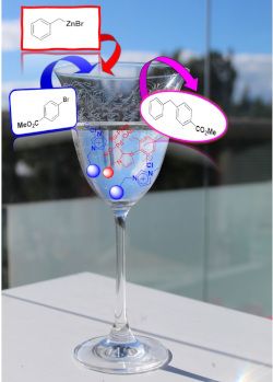
Self-assembled coordination thioether silver(I) macrocyclic complexes for homogeneous catalysis
- Zhen Cao,
- Aline Lacoudre,
- Cybille Rossy and
- Brigitte Bibal
Beilstein J. Org. Chem. 2019, 15, 2465–2472, doi:10.3762/bjoc.15.239
- complexes 1a–d were evaluated as homogeneous catalysts in two tandem addition/cycloisomerization reactions using alkynes 2 and 3. 2-Alkynylbenzaldehyde 2 [58][59] was chosen as the first model substrate for a cyclization reaction in the presence of methanol as a second nucleophile. This tandem addition
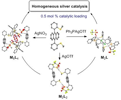
- the coordinated ligands (head-to-head or head-to-tail) resulting into different spatial arrangements. In solution, the architectures of silver(I) complexes with ligand syn-1 seemed to be similar to the solid-state structures. The silver(I) complexes were evaluated as homogeneous catalysts in two

Graphical Abstract

Scheme 1: Synthesis of ligand 1, as its syn-atropisomer.

Figure 1: X-ray structures of complex 1a, as two diastereoisomeric macrocycles (R,S-1)2·(AgOTf)2 with ligands...

Figure 2: X-ray structure of complex 1c, as a (R,S-1)4·(AgNO3)6 cage with three nitrate anions as coordinatin...

Figure 3: X-ray structure of complex 1d, as a racemic mixture of (R,R)- and (S,S)-(syn-1)·(PPh3AgOTf)2.

Figure 4: Variable temperature 1H NMR of complex 1a in CDCl3 (7 mM) from −30 °C to 60 °C.
Aqueous olefin metathesis: recent developments and applications
- Valerio Sabatino and
- Thomas R. Ward
Beilstein J. Org. Chem. 2019, 15, 445–468, doi:10.3762/bjoc.15.39

- ammonium tags Classical metathesis catalysts such as G-II and HG-II are among the most active, stable and versatile ruthenium complexes. Despite their high activity and remarkable stability, they are sparingly soluble in neat water, thus challenging their use as homogeneous catalysts in pure water. To

Graphical Abstract

Scheme 1: Most common metathesis reactions. Ring-opening metathesis polymerization (ROMP), acyclic diene meta...

Scheme 2: Catalytic cycle for metathesis proposed by Chauvin.

Figure 1: Some of the most representative catalysts for aqueous metathesis. a) Well-defined ruthenium catalys...

Scheme 3: First aqueous ROMP reactions catalyzed by ruthenium(III) salts.

Scheme 4: Degradation pathway of first generation Grubbs catalyst (G-I) in methanol.

Scheme 5: Synthesis of Blechert-type catalysts 19 and 20.

Figure 2: Chemical structure and components of amphiphilic molecule PTS and derivatives.

Scheme 6: RCM of selected substrates in the presence of the surfactant PTS. Conditionsa: The reaction was car...

Scheme 7: RCM reactions of substrates 31 and 33 with the encapsulated G-II catalyst.

Scheme 8: Living ROMP of norbornene derivatives 35 and 36 with phosphine-based catalysts bearing quaternary a...

Scheme 9: Synthesis of water-soluble catalysts 3 and 4 bearing quaternary ammonium tags.

Scheme 10: In situ formation of catalyst 5 bearing a quaternary ammonium group.

Scheme 11: Catalyst recycling of an ammonium-bearing catalyst.

Scheme 12: Removal of the water-soluble catalyst 12 through host–guest interaction with silica-gel-supported β...

Scheme 13: Selection of artificial metathases reported by Ward and co-workers (ArM 1 based on biotin–(strept)a...

Figure 3: In vivo metathesis with an artificial metalloenzyme based on the biotin–streptavidin technology.

Scheme 14: Artificial metathase based on covalent anchoring approach. α-Chymotrypsin interacts with catalyst 66...

Scheme 15: Assembling an artificial metathase (ArM 4) based on the small heat shock protein from M. Jannaschii...

Scheme 16: Artificial metathases based on cavity-size engineered β-barrel protein nitrobindin (NB4exp). The HG...

Scheme 17: Artificial metathase based on cutinase (ArM 8) and resulting metathesis activities.

Scheme 18: Site-specific modification of proteins via aqueous cross-metathesis. The protein structure is based...

Scheme 19: a) Allyl homocysteine (Ahc)-modified proteins as CM substrates. b) Incorporation of Ahc in the Fc p...

Scheme 20: On-DNA cross-metathesis reaction of allyl sulfide 99.

Scheme 21: Preparation of BODIPY-containing profluorescent probes 102 and 104.

Scheme 22: Metathesis-based ethylene detection in live cells.

Scheme 23: First example of stapled peptides via olefin metathesis.
The activity of indenylidene derivatives in olefin metathesis catalysts
- Maria Voccia,
- Steven P. Nolan,
- Luigi Cavallo and
- Albert Poater
Beilstein J. Org. Chem. 2018, 14, 2956–2963, doi:10.3762/bjoc.14.275

- ] developed well-defined homogeneous catalysts that the area truly blossomed. Using a metal carbene complex as a catalyst, making use of the Chauvin mechanism, olefin metathesis consists of the redistribution of two carbon–carbon double bonds [9]. The metal and its ligand environment in both ruthenium and

Graphical Abstract

Scheme 1: Catalysts studied by DFT calculations.

Scheme 2: Precatalyst initiation in olefin metathesis (L = NHC ligand).

Figure 1: Topographic steric maps (plane xy) of the NHC ligands of species I for the studied SIMes–Ru complex...

Figure 2: Intermediate II for catalysts a) 1 and b) 5 (important bond lengths are given in Å).
An overview on recent advances in the synthesis of sulfonated organic materials, sulfonated silica materials, and sulfonated carbon materials and their catalytic applications in chemical processes
- Hashem Sharghi,
- Pezhman Shiri and
- Mahdi Aberi
Beilstein J. Org. Chem. 2018, 14, 2745–2770, doi:10.3762/bjoc.14.253

- ; biodiesel synthesis; sulfonated carbon materials; sulfonated industrial and laboratory products; sulfonated organic materials; sulfonated silica materials; Review 1. Introduction Mineral acids (sulfuric acid, sulfonic acid, hydrochloric acid, phosphoric acid, and boric acid) as homogeneous catalysts were
- homogeneous catalysts (Scheme 7). Significantly, IL catalysts 47b,c could be extracted from the reaction mixture for six consecutive cycles. In all runs, IL catalysts 47b,c showed excellent catalytic activity. The FTIR spectra of two of these reused ILs after the 6th run and the fresh ILs have been used to
- are the first option for heterogenizing the homogeneous catalysts. These solid supports have greatly functionalized with various functional groups [55]. In this regard, different functionalized SiO2 containing sulfonic acid groups as novel acid catalysts were employed in different synthetic and

Graphical Abstract

Figure 1: Different types of sulfonated materials as acid catalysts.

Scheme 1: Synthetic route of 3-methyl-1-sulfo-1H-imidazolium metal chloride ILs and their catalytic applicati...

Scheme 2: Synthetic route of 1,3-disulfo-1H-imidazolium transition metal chloride ILs and their catalytic app...

Scheme 3: Synthetic route of 1,3-disulfoimidazolium carboxylate ILs and their catalytic applications in the s...

Scheme 4: Synthetic route of [BiPy](HSO3)2Cl2 and [Dsim]HSO4 ILs and their catalytic applications for the syn...

Scheme 5: The catalytic applications of (C4(DABCO-SO3H)2·4Cl) IL for the synthesis of spiro-isatin derivative...

Scheme 6: The catalytic applications of (C4(DABCO-SO3H)2·4Cl) IL for the synthesis of bis 2-amino-4H-pyran de...

Scheme 7: The synthetic route of N,N-disulfo-1,1,3,3-tetramethylguanidinium carboxylate ILs and their catalyt...

Scheme 8: The catalytic application of 1-methyl-3-sulfo-1H-imidazolium tetrachloroferrate IL in the synthesis...

Scheme 9: The synthetic route of 3-sulfo-1H-imidazolopyrimidinium hydrogen sulfate IL and its catalytic appli...

Scheme 10: The results for the synthesis of bis(indolyl)methanes and di(bis(indolyl)methyl)benzenes in the pre...

Scheme 11: The catalytic applications of 1-(1-sulfoalkyl)-3-methylimidazolium chloride acidic ILs for the hydr...

Scheme 12: The synthetic route of immobilized 1,4-diazabicyclo[2.2.2]octanesulfonic acid chloride on SiO2 and ...

Scheme 13: The catalytic application of a silica-bonded sulfoimidazolium chloride for the synthesis of 12-aryl...

Scheme 14: The synthetic route of the SBA-15-Ph-SO3H and its catalytic applications for the synthesis of 2H-in...

Scheme 15: The synthetic route for heteropolyanion-based ionic liquids immobilized on mesoporous silica SBA-15...

Scheme 16: Some mechanism aspects of SSA catalyst for the protection of amine derivatives.

Scheme 17: The synthetic route for MWCNT-SO3H and its catalytic application for the synthesis of N-substituted...

Scheme 18: The sulfonic acid-functionalized polymers (P-SO3H) covalently grafted on multi-walled carbon nanotu...

Scheme 19: The transesterification reaction in the presence of S-MWCNTs.

Scheme 20: The synthetic route for the new hypercrosslinked supermicroporous polymer via the Friedel–Crafts al...

Scheme 21: The synthetic route for a new microporous copolymer via the Friedel–Crafts alkylation reaction of t...

Scheme 22: The synthetic route for sulfonated polynaphthalene and its catalytic application for the amidoalkyl...

Scheme 23: The synthetic route of the acidic carbon material and its catalytic application in the etherificatio...

Scheme 24: The synthetic route of the acidic carbon materials and their catalytic applications for the esterif...

Scheme 25: The sulfonated MWCNTs.

Scheme 26: The sulfonated nanoscaled diamond powder for the dehydration of D-xylose into furfural.

Scheme 27: The synthetic route and catalytic application of the GR-SO3H.
Cobalt- and rhodium-catalyzed carboxylation using carbon dioxide as the C1 source
- Tetsuaki Fujihara and
- Yasushi Tsuji
Beilstein J. Org. Chem. 2018, 14, 2435–2460, doi:10.3762/bjoc.14.221

- [2 + 2 + 2] cycloaddition of diynes and CO2 proceeds to afford pyrones. Keywords: carbon dioxide; carboxylation; cobalt; homogeneous catalysts; rhodium; Introduction Carbon dioxide (CO2) is one of the most important materials as renewable feedstock [1][2][3][4]. However, the thermodynamic and

Graphical Abstract

Scheme 1: Optimization of the Co-catalyzed carboxylation of 1a.

Scheme 2: Co-catalyzed carboxylation of propargyl acetates 1.

Scheme 3: Plausible reaction mechanism for the Co-catalyzed carboxylation of propargyl acetates 1.

Scheme 4: Optimization of the Co-catalyzed carboxylation of 3a.

Scheme 5: Co-catalyzed carboxylation of vinyl triflates 3.

Scheme 6: Co-catalyzed carboxylation of a sterically hindered aryl triflate 5.

Scheme 7: Optimization of the Co-catalyzed carboxylation of 7a.

Scheme 8: Scope of the reductive carboxylation of α,β-unsaturated nitriles 7.

Scheme 9: Scope of the carboxylation of α,β-unsaturated carboxamides 9.

Scheme 10: Optimization of the Co-catalyzed carboxylation of 11a.

Scheme 11: Scope of the carboxylation of allylarenes 11.

Scheme 12: Scope of the carboxylation of 1,4-diene derivatives 14.

Scheme 13: Plausible reaction mechanism for the Co-catalyzed C(sp3)–H carboxylation of allylarenes.

Scheme 14: Optimization of the Co-catalyzed carboxyzincation of 16a.

Scheme 15: Derivatization of the carboxyzincated product.

Scheme 16: Co-catalyzed carboxyzincation of alkynes 16.

Scheme 17: Plausible reaction mechanism for the Co-catalyzed carboxyzincation of alkynes 16.

Scheme 18: Co-catalyzed four-component coupling of alkynes 16, acrylates 18, CO2, and zinc.

Scheme 19: Proposed reaction mechanism for the Co-catalyzed four-component coupling.

Scheme 20: Visible-light-driven hydrocarboxylation of alkynes.

Scheme 21: Visible-light-driven synthesis of γ-hydroxybutenolides from ortho-ester-substituted aryl alkynes.

Scheme 22: One-pot synthesis of coumarines and 2-quinolones via hydrocarboxylation/alkyne isomerization/cycliz...

Scheme 23: Proposed reaction mechanism for the Co-catalyzed carboxylative cyclization of ortho-substituted aro...

Scheme 24: Rh-catalyzed carboxylation of arylboronic esters 25.

Scheme 25: Rh-catalyzed carboxylation of alkenylboronic esters 27.

Scheme 26: Plausible reaction mechanism for the Rh-catalyzed carboxylation of arylboronic esters 25.

Scheme 27: Ligand effect on the Rh-catalyzed carboxylation of 2-phenylpyridine 29a.

Scheme 28: Rh-catalyzed chelation-assisted C(sp2)–H bond carboxylation with CO2.

Scheme 29: Reaction mechanism for the Rh-catalyzed C(sp2)–H carboxylation of 2-pyridylarenes 29.

Scheme 30: Carboxylation of C(sp2)–H bond with CO2.

Scheme 31: Carboxylation of C(sp2)–H bond with CO2.

Scheme 32: Reaction mechanism for the Rh-catalyzed C(sp2)–H carboxylation of 2-arylphenols 34.

Scheme 33: Hydrocarboxylation of styrene derivatives with CO2.

Scheme 34: Hydrocarboxylation of α,β-unsaturated esters with CO2.

Scheme 35: Asymmetric hydrocarboxylation of α,β-unsaturated esters with CO2.

Scheme 36: Proposed reaction mechanism for the Rh-catalyzed hydrocarboxylation of C–C double bonds with CO2.

Scheme 37: Visible-light-driven hydrocarboxylation with CO2.

Scheme 38: Visible-light-driven Rh-catalyzed hydrocarboxylation of C–C double bonds with CO2.

Scheme 39: Optimization of reaction conditions on the Rh-catalyzed [2 + 2 + 2] cycloaddition of diyne 42a and ...

Scheme 40: [2 + 2 + 2] Cycloaddition of diyne and CO2.

Scheme 41: Proposed reaction pathways for the Rh-catalyzed [2 + 2 + 2] cycloaddition of diyne and CO2.
Efficient catalytic alkyne metathesis with a fluoroalkoxy-supported ditungsten(III) complex
- Henrike Ehrhorn,
- Janin Schlösser,
- Dirk Bockfeld and
- Matthias Tamm
Beilstein J. Org. Chem. 2018, 14, 2425–2434, doi:10.3762/bjoc.14.220

- applications of alkyne metathesis since this protocol represents a convenient approach to alkyne metathesis catalysts in two steps starting from WCl4. Selected homogeneous catalysts for alkyne metathesis. Molecular structure of W2F3·NHMe2 with thermal displacement parameters drawn at 50% probability. Hydrogen

Graphical Abstract

Figure 1: Selected homogeneous catalysts for alkyne metathesis.

Scheme 1: Synthesis of alkylidyne complex V from bimetallic [(t-BuO)3W≡W(Ot-Bu)3]; the catalytically active d...

Scheme 2: Synthesis of hexakis(fluoroalkoxide) dimers Mo2F6 [73] and W2F3.

Figure 2: Molecular structure of W2F3·NHMe2 with thermal displacement parameters drawn at 50% probability. Hy...

Scheme 3: Preparation of the alkylidyne complex WPhF3.

Figure 3: Molecular structure of WPhF3 with thermal displacement parameters drawn at 50% probability. Hydroge...

Scheme 4: Self-metathesis of 1-phenyl-1-propyne derivatives by tungsten complexes W2F3 and WPhF3.

Figure 4: Conversion versus time diagram for the self-metathesis of 1-phenyl-1-propyne catalyzed by 0.5 mol % ...
Nanoreactors for green catalysis
- M. Teresa De Martino,
- Loai K. E. A. Abdelmohsen,
- Floris P. J. T. Rutjes and
- Jan C. M. van Hest
Beilstein J. Org. Chem. 2018, 14, 716–733, doi:10.3762/bjoc.14.61

- environmental point of view. A good method for homogeneous catalysts separation and reuse is offered by the use of biphasic liquid–liquid systems. Recycling can be achieved in the reactor when the organic phase is sampled out, while the aqueous phase containing the catalyst is retained into the vessel, enabling
- for continuous processing. The main issue that has to be solved in such set-up is the tolerability of the catalyst to water (its solubility, its activity, etc.) [55]. A strategy to overcome this problem is the inclusion and confinement of the homogeneous catalysts into a host nano-architecture [56
- ]. In this review we will highlight some typical nanoreactors that are used to accommodate homogeneous catalysts, holding promise in green organic synthesis. A division will be made between self-assembled nanoreactors, section 2, and covalent systems, section 3. 2. Self-assembled nanoreactors Self

Graphical Abstract

Figure 1: Assembly of catalyst-functionalized amphiphilic block copolymers into polymer micelles and vesicles...

Scheme 1: C–N bond formation under micellar catalyst conditions, no organic solvent involved. Adapted from re...

Scheme 2: Suzuki−Miyaura couplings with, or without, ppm Pd. Conditions: ArI 0.5 mmol 3a, Ar’B(OH)2 (0.75–1.0...

Figure 2: PQS (4a), PQS attached proline catalyst 4b. Adapted from reference [26]. Copyright 2012 American Chemic...

Figure 3: 3a) Schematic representation of a Pickering emulsion with the enzyme in the water phase (i), or wit...

Scheme 3: Cascade reaction with GOx and Myo. Adapted from reference [82].

Figure 4: Cross-linked polymersomes with Cu(OTf)2 catalyst. Reprinted with permission from [15].

Figure 5: Schematic representation of enzymatic polymerization in polymersomes. (A) CALB in the aqueous compa...

Figure 6: Representation of DSN-G0. Reprinted with permission from [100].

Figure 7: The multivalent esterase dendrimer 5 catalyzes the hydrolysis of 8-acyloxypyrene 1,3,6-trisulfonate...

Figure 8: Conversion of 4-NP in five successive cycles of reduction, catalyzed by Au@citrate, Au@PEG and Au@P...
Heterogeneous Pd catalysts as emulsifiers in Pickering emulsions for integrated multistep synthesis in flow chemistry
- Katharina Hiebler,
- Georg J. Lichtenegger,
- Manuel C. Maier,
- Eun Sung Park,
- Renie Gonzales-Groom,
- Bernard P. Binks and
- Heidrun Gruber-Woelfler
Beilstein J. Org. Chem. 2018, 14, 648–658, doi:10.3762/bjoc.14.52

- strategies to realise heterogeneous palladium catalysis [21]. Immobilisation of catalytic systems on solid supports can mitigate a lot of problems of homogeneous catalysts, for example, it allows a straightforward removal of the catalyst from the reaction system. However, most heterogeneous approaches

Graphical Abstract

Figure 1: Targeted integrated multistep synthesis of valsartan (1) and sacubitril (2).

Scheme 1: Suzuki–Miyaura coupling of phenylboronic acid 3 with various bromoarenes 4a–e (a: R1 = H, R2 = CH3; ...

Figure 2: Particle size distribution of Ce0.495Sn0.495Pd0.01O2–δ after size reduction via milling and separat...

Figure 3: Optical microscope images of fresh aqueous dispersions, 0.05 wt %, of (a) Ce0.495Sn0.495Pd0.01O2–δ ...

Figure 4: Photos of vessels containing cyclohexane-in-water emulsions stabilised by particles of Ce0.495Sn0.4...

Figure 5: Optical microscopy images of cyclohexane-in-water emulsions of Figure 4 after one month for particle concen...

Figure 6: (top) Mean emulsion droplet diameter after 30 min as a function of particle concentration for syste...

Figure 7: Mean particle diameter in aqueous dispersions as a function of Ce0.495Sn0.495Pd0.01O2–δ concentrati...

Figure 8: Variation of the zeta potential and pH value of aqueous dispersions of Ce0.495Sn0.495Pd0.01O2–δ par...

Figure 9: (a) Appearance of octane-in-water emulsions with time at 0.05 wt % of Ce0.495Sn0.495Pd0.01O2–δ (lef...

Figure 10: (a) Variation of droplet diameter with particle concentration for octane-in-water emulsions stabili...

Figure 11: (a) Variation of droplet diameter with particle concentration for toluene-in-water emulsions stabil...