Search for "acceptors" in Full Text gives 308 result(s) in Beilstein Journal of Organic Chemistry. Showing first 200.
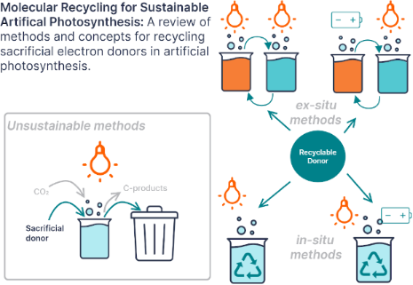
Beilstein J. Org. Chem. 2022, 18, 722–731, doi:10.3762/bjoc.18.72
Graphical Abstract
Figure 1: Prenylated aromatic metabolites are involved in cellular processes like cell respiration (coenzyme Q...
Figure 2: Homology clustering of Ptases encoded in marine Flavobacteria and Saccharomonospora species (G1–G4,...
Figure 3: Regional alignment of ubiA-297 of Maribacter sp. MS6 (EU359911.1) and homologous genes in Z. uligin...
Figure 4: A) Amino acid alignment and binding residues of UbiA-297. G2-Ptases are illustrated in the grey box...
Figure 5: Evaluation of substrate specificity of UbiA-297. Accepted substrates are shown in red, while no pro...
Figure 6: A) Reaction scheme of UbiA-297 catalyzing the assumed para-directed farnesylation of 8-HQA; B) calc...
Beilstein J. Org. Chem. 2022, 18, 597–630, doi:10.3762/bjoc.18.62
Graphical Abstract
Figure 1: Butterfly 1 (Figure was reprinted with permission from [45]. Copyright 2012 American Chemical Society. ...
Figure 2: Synthesis of the three-component heteroleptic molecular boat 8 and its use as a catalyst for the Kn...
Figure 3: Synthesis of the two-component triangle 14 and three-component heteroleptic prism 15 [59]. Figure was a...
Figure 4: Catalytic Michael addition reaction using the urea-decorated molecular prism 15 [59].
Figure 5: Self-assembly of two-component tetragonal prismatic architectures with different cavity size. Figur...
Figure 6: Construction of artificial LHS using rhodamine B as an acceptor and 24b as donor generating a photo...
Figure 7: Synthesis of supramolecular spheres with varying [AuCl] concentration inside the cavity. Figure was...
Figure 8: Hydroalkoxylation reaction of γ-allenol 34 in the presence of [AuCl]-encapsulated molecular spheres ...
Figure 9: Two-component heteroleptic triangles of different size containing a BINOL functionality. Figure was...
Figure 10: Asymmetric conjugate addition of chalcone 42 with trans-styrylboronic acid (43) catalyzed by BINOL-...
Figure 11: Encapsulation of monophosphoramidite-Rh(I) catalyst into a heteroleptic tetragonal prismatic cage 47...
Figure 12: (a) Representations of the basic HETPYP, HETPHEN, and HETTAP complex motifs. (b) The three-componen...
Figure 13: Two representative four-component rotors, with a (top) two-arm stator and (bottom) a four-arm stato...
Figure 14: Four-component rotors with a monohead rotator. Figure was adapted with permission from [94]. Copyright ...
Figure 15: (left) Click reaction catalyzed by rotors [Cu2(55)(60)(X)]2+. (right) Yield as a function of the ro...
Figure 16: A supramolecular AND gate. a) In truth table state (0,0) two nanoswitches serve as the receptor ens...
Figure 17: Two supramolecular double rotors (each has two rotational axes) and reference complex [Cu(78)]+ for...
Figure 18: The slider-on-deck system (82•X) (X = 83, 84, or 85). Figure is from [98] and was reprinted from the jo...
Figure 19: Catalysis of a conjugated addition reaction in the presence of the slider-on-deck system (82•X) (X ...
Figure 20: A rotating catalyst builds a catalytic machinery. For catalysis of the catalytic machinery, see Figure 21. F...
Figure 21: Catalytic machinery. Figure was adapted from [100] (“Evolution of catalytic machinery: three-component n...
Figure 22: An information system based on (re)shuffling components between supramolecular structures [99]. Figure ...
Figure 23: Switching between dimeric heteroleptic and homoleptic complex for OFF/ON catalytic formation of rot...
Figure 24: A chemically fueled catalytic system [112]. Figure was adapted from [112]. Copyright 2021 American Chemical S...
Figure 25: (Top) Operation of a fuel acid. (Bottom) Knoevenagel addition [112].
Figure 26: Development of the yield of Knoevenagel product 118 in a fueled system [112]. Figure was reprinted with ...
Figure 27: Weak-link strategy to increased catalytic activity in epoxide opening [119]. Figure was adapted from [24]. C...
Figure 28: A ON/OFF polymerization switch based on the weak-link approach [118]. Figure was reprinted with permissi...
Figure 29: A weak-link switch turning ON/OFF a Diels–Alder reaction [132]. Figure was reprinted with permission fro...
Figure 30: A catalyst duo allowing selective activation of one of two catalytic acylation reactions [133] upon subs...
Figure 31: A four-state switchable nanoswitch (redrawn from [134]).
Figure 32: Sequential catalysis as regulated by nanoswitch 138 and catalyst 139 in the presence of metal ions ...
Figure 33: Remote control of ON/OFF catalysis administrated by two nanoswitches through ion signaling (redrawn...
Beilstein J. Org. Chem. 2022, 18, 429–437, doi:10.3762/bjoc.18.45
Graphical Abstract
Scheme 1:
Graphical representation of the fabrication of supramolecular m-TPEWP5G-EsY self-assembled photocat...
Figure 1: 1H NMR (400 MHz, D2O, 298 K) spectra of m-TPEWP5 (1.0 mM), m-TPEWP5 (1.0 mM) + G (1.0 mM), and G (1...
Figure 2: (a) Fluorescence spectra of m-TPEWP5 (1 × 10⁻⁵ M) with different concentrations of G (0 to 1.2 equi...
Figure 3:
TEM images of (a) m-TPEWP5G; (b) m-TPEWP5
G-EsY. [m-TPEWP5] = 1 × 10⁻⁴ M, [G] = 1 × 10⁻⁴ M, [EsY] = ...
Figure 4:
(a) Normalized absorption and emission spectra of the EsY acceptor and the m-TPEWP5G donor assembly...
Scheme 2:
Products from 2-bromo-1-phenylethanone dehalogenation reactions in the presence of m-TPEWP5G-EsY na...
Figure 5:
Proposed mechanism for the 2-bromo-1-phenylethanone dehalogenation reaction mediated by m-TPEWP5G-E...
Beilstein J. Org. Chem. 2022, 18, 303–308, doi:10.3762/bjoc.18.34
Graphical Abstract
Scheme 1: Reaction conducted according to the Ellman protocol.
Figure 1: Asymmetric unit of 2a, with the atom-numbering scheme. The crystallographic reference system is als...
Figure 2: Substrate scope of the borylcopper-mediated homocoupling of oxindole-based N-tert-butanesulfinyl im...
Scheme 2: Proposed mechanism for the borylcopper-mediated homocoupling of ketimines 1.
Beilstein J. Org. Chem. 2021, 17, 2629–2641, doi:10.3762/bjoc.17.176
Graphical Abstract
Figure 1: Catalyst design principles.
Scheme 1: Synthesis of isothiocyanate 3a and isocyanate 3b.
Scheme 2: Synthesis of sulfinylthioureas C1 and ureas C2.
Scheme 3: Synthesis of adducts 8a,d,f in solution.
Figure 2: DFT-calculated (PBEh-3c/def2-SV(P)//M06-2X/def2-TZVP) structures of catalyst (S,R) and (S,S)-C2, en...
Figure 3: a) Arrangements of reactants in the transition states; b) DFT-calculated (PBEh-3c/def2-SV(P)//M06-2...
Figure 4: DFT-calculated (PBEh-3c/def2-SV(P)//M06-2X/def2-TZVP) reaction profile for the Michael addition of ...
Beilstein J. Org. Chem. 2021, 17, 2585–2610, doi:10.3762/bjoc.17.173
Graphical Abstract
Scheme 1: Asymmetric aza-Michael addition catalyzed by cinchona alkaloid derivatives.
Scheme 2: Intramolecular 6-exo-trig aza-Michael addition reaction.
Scheme 3: Asymmetric aza-Michael/Michael addition cascade reaction of 2-nitrobenzofurans and 2-nitrobenzothio...
Scheme 4: Asymmetric aza-Michael addition of para-dienone imide to benzylamine.
Scheme 5: Asymmetric synthesis of chiral N-functionalized heteroarenes.
Beilstein J. Org. Chem. 2021, 17, 2496–2504, doi:10.3762/bjoc.17.166
Graphical Abstract
Scheme 1: Schematic representation of the polymer synthesis of P1 and P2.
Figure 1: DSC-analysis of the polymers P1 and P2 (second heating and cooling cycle; 20 K/min for heating and ...
Figure 2: DMTA analysis of P1 and P2 showing the transition at around 130 °C due to the reversible π–π intera...
Figure 3: Frequency sweeps of polymers P1 (left) and P2 (right).
Figure 4: Temperature dependent IR spectra of P1 drop casted on KBr in the C=C (1570–1605 cm−1) and C=O stret...
Figure 5: Schematic representation of the first healing of P1 at 150 °C.
Beilstein J. Org. Chem. 2021, 17, 2462–2476, doi:10.3762/bjoc.17.163
Graphical Abstract
Scheme 1: Ag/I2-mediated electrophilic annulation of 2-en-4-ynyl azides 1.
Scheme 2: The proposed mechanism of Ag-catalyzed aza-annulation.
Scheme 3: The proposed mechanism of I2-mediated aza-annulation.
Scheme 4: Copper-catalyzed amination of (E)-2-en-4-ynyl azides 1.
Scheme 5: The proposed mechanism of copper-catalyzed amination.
Scheme 6: The derivatization of sulfonated aminonicotinates.
Scheme 7: Copper-catalyzed chalcogenoamination of (E)-2-en-4-ynyl azides 1.
Scheme 8: The possible mechanism of chalcogenoamination.
Scheme 9: The derivatization of 5‑selenyl- and 5-sulfenyl-substituted nicotinates.
Scheme 10: The tandem reaction of nitriles, Reformatsky reagents, and 1,3-enynes.
Scheme 11: Nickel-catalyzed [4 + 2]-cycloaddition of 3-azetidinones with 1,3-enynes.
Scheme 12: Electrophilic iodocyclization of 2-nitro-1,3-enynes to pyrroles.
Scheme 13: Electrophilic halogenation of 2-trifluoromethyl-1,3-enynes to pyrroles.
Scheme 14: Copper-catalyzed cascade cyclization of 2-nitro-1,3-enynes with amines.
Scheme 15: Tandem cyclization of 2-nitro-1,3-enynes, Togni reagent II, and amines.
Scheme 16: Tandem cyclization of 2-nitro-1,3-enynes, TMSN3, and amines.
Scheme 17: Cascade cyclization of 6-hydroxyhex-2-en-4-ynals to pyrroles.
Scheme 18: Au/Ag-catalyzed oxidative aza-annulation of 1,3-enynyl azides.
Scheme 19: The plausible mechanism of Au/Ag-catalyzed oxidative aza-annulation.
Scheme 20: Synthesis of 2-tetrazolyl-substituted 3-acylpyrroles from enynals.
Scheme 21: CuH-catalyzed coupling reaction of 1,3-enynes and nitriles to pyrroles.
Scheme 22: The mechanism of CuH-catalyzed coupling of 1,3-enynes and nitriles to pyrroles.
Beilstein J. Org. Chem. 2021, 17, 2260–2269, doi:10.3762/bjoc.17.144
Graphical Abstract
Figure 1: Proposed structural modifications to obtain triazole derivatives 1a, b and 2a–j.
Scheme 1: Synthetic route of the triazole derivatives 1a,b, and 2a–j.
Figure 2: Asymmetric unit representation of the 1,2,3-triazole derivative 2b. Displacement ellipsoids are dra...
Figure 3: Screening of the triazole derivatives of imatinib 1a,b, and 2a–j at concentrations of 1 μM and 10 μ...
Figure 4: Interaction maps of IMT, 2c, 2d, and 2g with the BCR-Abl-1 structure (PDB code: 3PYY), showing ster...
Beilstein J. Org. Chem. 2021, 17, 2164–2185, doi:10.3762/bjoc.17.139
Graphical Abstract
Figure 1: Chemical structure, numbering scheme, and resonance form of azulene.
Scheme 1: Synthesis of polyazulene-iodine (PAz-I2) and polyazulene-bromine (PAz-Br2) complexes.
Scheme 2: Synthesis of ‘true polyazulene’ 3 or 3’ by cationic polymerization.
Scheme 3: Synthesis of 1,3-polyazulene 5 by Yamamoto protocol.
Scheme 4: Synthesis of 4,7-dibromo-6-(n-alkyl)azulenes 12–14.
Scheme 5: Synthesis of (A) 4,7-diethynyl-6-(n-dodecyl)azulene (16) and (B) 4,7-polyazulene 17 containing an e...
Scheme 6: Synthesis of directly connected 4,7-polyazulenes 18–20.
Scheme 7: Synthesis of (A) tert-butyl N-(6-bromoazulen-2-yl)carbamate (27), (B) dimeric aminoazulene 29, and ...
Figure 2: Iminium zwitterionic resonance forms of poly[2(6)-aminoazulene] 31.
Scheme 8: Synthesis of poly{1,3-bis[2-(3-alkylthienyl)]azulene} 33–38.
Scheme 9: Synthesis of polymer ruthenium complexes 40–43.
Scheme 10: Synthesis of 4,7-polyazulenes 45 containing a thienyl linker.
Scheme 11: Synthesis of azulene-bithiophene 48 and azulene-benzothiadiazole 52 copolymers. Conditions: (a): (i...
Scheme 12: Synthesis of azulene-benzodithiophene copolymer 54 and azulene-bithiophene copolymer 56.
Scheme 13: Synthesis of (A) 5,5’-bis(trimethylstannyl)-3,3’-didodecyl-2,2’-bithiophene (60) and (B) azulene-bi...
Scheme 14: Synthesis of 1,3-bisborylated azulene 67.
Scheme 15: Synthesis of D–A-type azulene-DPP copolymers 69, 71, and 72. Conditions: (a) Pd(PPh3)4, K2CO3, Aliq...
Scheme 16: Synthesis of the key precursor TBAzDI 79.
Scheme 17: Synthesis of TBAzDI-based polymers 81 and 83. Conditions: (a) P(o-tol)3, Pd2(dba)3, PivOH, Cs2CO3, ...
Scheme 18: Synthesis of (A) 1,3-dibromo-2-arylazulene 92–98 and (B) 2-arylazulene-thiophene copolymers 99–101.
Scheme 19: Synthesis of (A) poly[2,7-(9,9-dialkylfluorenyl)-alt-(1’,3’-azulenyl)] 106–109, (B) 1,3-bis(7-bromo...
Scheme 20: Synthesis of azulene-fluorene copolymers 117–121 containing varying ratios of 1,3- and 4,7-connecte...
Scheme 21: Synthesis of (A) 2,6-dibromoazulene (125), (B) azulene-fluorene copolymer 126, and (C) azulene-fluo...
Scheme 22: Synthesis of 2-arylazulene-fluorene copolymers 131–134.
Scheme 23: Synthesis of azulene-fluorene-benzothiadiazole terpolymers 136–138.
Scheme 24: Synthesis of azulene-carbazole-benzothiadiazole-conjugated polymers 140–144.
Scheme 25: Synthesis of (A) azulene-2-yl methacrylate (146) and (B) the triazole-containing azulene methacryla...
Scheme 26: Synthesis of (A) azulene methacrylate polymer 151 and (B) triazole-containing azulene methacrylate ...
Scheme 27: Synthesis of azulene methyl methacrylate polymers 154, 155 (A and B) and azulene-sulfobetaine metha...
Beilstein J. Org. Chem. 2021, 17, 2077–2084, doi:10.3762/bjoc.17.134
Graphical Abstract
Figure 1: Strategy for the synthesis of glutamate and pyroglutamate derivatives and several natural products ...
Figure 2: Effect of the aryl substituent on reaction efficiency and selectivity.
Figure 3: Proposed transition state model.
Beilstein J. Org. Chem. 2021, 17, 2051–2066, doi:10.3762/bjoc.17.132
Graphical Abstract
Figure 1: Some commercial Ru-based catalysts used in the current work.
Figure 2: Synthesis of divinylated cyclopentane-fused isoxazolines [41].
Figure 3: Various fluorine-containing olefins used in the current work.
Scheme 1: Cross-metathesis of divinylated isoxazoline (±)-4 with 1,1,1,3,3,3-hexafluoropropan-2-yl acrylate (...
Scheme 2: Cross-metathesis of divinylated isoxazoline (±)-4 with 2,2,3,3,4,4,4-heptafluorobutyl acrylate (7d)....
Scheme 3: Cross-metathesis of divinylated isoxazoline (±)-4 with 2,2,2-trifluoroethyl acrylate (7e).
Scheme 4: Cross-metathesis of divinylated isoxazoline (±)-4 with 1,1,1-trifluoro-2-(trifluoromethyl)pent-4-en...
Scheme 5: Cross-metathesis of divinylated isoxazoline (±)-4 with 8-(allyloxy)-1,1,1,2,2,3,3,4,4,5,5,6,6-tride...
Scheme 6: Cross-metathesis of divinylated isoxazoline (±)-4 with 4-fluorostyrene (7h).
Scheme 7: Selective CM of divinylated isoxazoline (±)-5 with 1,1,1,3,3,3-hexafluoropropan-2-yl acrylate (7c).
Scheme 8: Cross-metathesis of divinylated isoxazoline (±)-5 with 2,2,3,3,4,4,4-heptafluorobutyl acrylate (7d)....
Scheme 9: Cross-metathesis of divinylated isoxazoline (±)-5 with 2,2,2-trifluoroethyl acrylate (7e).
Scheme 10: Cross-metathesis of divinylated isoxazoline (±)-5 with 1,1,1-trifluoro-2-(trifluoromethyl)pent-4-en...
Scheme 11: Cross-metathesis of divinylated isoxazoline (±)-5 with 8-(allyloxy)-1,1,1,2,2,3,3,4,4,5,5,6,6-tride...
Scheme 12: Cross-metathesis of divinylated isoxazoline (±)-5 with 4-fluorostyrene (7h).
Scheme 13: Cross-metathesis of divinylated isoxazoline (±)-6 with 1,1,1,3,3,3-hexafluoropropan-2-yl acrylate (...
Scheme 14: Cross-metathesis of divinylated isoxazoline (±)-6 with 2,2,3,3,4,4,4-heptafluorobutyl acrylate (7d)....
Scheme 15: Cross-metathesis of divinylated isoxazoline (±)-6 with 2,2,2-trifluoroethyl acrylate (7e).
Scheme 16: Cross-metathesis of divinylated isoxazoline (±)-6 with 1,1,1-trifluoro-2-(trifluoromethyl)pent-4-en...
Scheme 17: Cross-metathesis of divinylated isoxazoline (±)-6 with 8-(allyloxy)-1,1,1,2,2,3,3,4,4,5,5,6,6-tride...
Scheme 18: Cross-metathesis of divinylated isoxazoline (±)-6 with 4-fluorostyrene (7h).
Figure 4: Chemoselective CM reaction due to steric hindrance.
Beilstein J. Org. Chem. 2021, 17, 1981–2025, doi:10.3762/bjoc.17.129
Graphical Abstract
Figure 1: Overview of the methods available for the synthesis of polysaccharides. For each method, advantages...
Figure 2: Overview of the classes of polysaccharides discussed in this review. Each section deals with polysa...
Scheme 1: Enzymatic and chemical polymerization approaches provide cellulose oligomers with a non-uniform dis...
Scheme 2: AGA of a collection of cellulose analogues obtained using BBs 6–9. Specifically placed modification...
Figure 3: Chemical structure of the different branches G, X, L, F commonly found in XGs. Names are given foll...
Scheme 3: AGA of XG analogues with defined side chains. The AGA cycle includes coupling (TMSOTf), Fmoc deprot...
Figure 4: Synthetic strategies and issues associated to the formation of the β(1–3) linkage.
Scheme 4: Convergent synthesis of β(1–3)-glucans using a regioselective glycosylation strategy.
Scheme 5: DMF-mediated 1,2-cis glycosylation. A) General mechanism and B) examples of α-glucans prepared usin...
Scheme 6: Synergistic glycosylation strategy employing a nucleophilic modulation strategy (TMSI and Ph3PO) in...
Scheme 7: Different approaches to produce xylans. A) Polymerization techniques including ROP, and B) enzymati...
Scheme 8: A) Synthesis of arabinofuranosyl-decorated xylan oligosaccharides using AGA. Representative compoun...
Scheme 9: Chemoenzymatic synthesis of COS utilizing a lysozyme-catalyzed transglycosylation reaction followed...
Scheme 10: Synthesis of COS using an orthogonal glycosylation strategy based on the use of two different LGs.
Scheme 11: Orthogonal N-PGs permitted the synthesis of COS with different PA.
Scheme 12: AGA of well-defined COS with different PA using two orthogonally protected BBs. The AGA cycle inclu...
Scheme 13: A) AGA of β(1–6)-N-acetylglucosamine hexasaccharide and dodecasaccharide. AGA includes cycles of co...
Figure 5: ‘Double-faced’ chemistry exemplified for ᴅ-Man and ʟ-Rha. Constructing β-Man linkages is considerab...
Figure 6: Implementation of a capping step after each glycosylation cycle for the AGA of a 50mer oligomannosi...
Scheme 14: AGA enabled the synthesis of a linear α(1–6)-mannoside 100mer 93 within 188 h and with an average s...
Scheme 15: The 151mer branched polymannoside was synthesized by a [30 + 30 + 30 + 30 + 31] fragment coupling. ...
Figure 7: PG stereocontrol strategy to obtain β-mannosides. A) The mechanism of the β-mannosylation reaction ...
Scheme 16: A) Mechanism of 1,2-cis stereoselective glycosylation using ManA donors. Once the ManA donor is act...
Figure 8: A) The preferred 4H3 conformation of the gulosyl oxocarbenium ion favors the attack of the alcohol ...
Scheme 17: AGA of type I rhamnans up to 16mer using disaccharide BB 115 and CNPiv PG. The AGA cycle includes c...
Figure 9: Key BBs for the synthesis of the O-antigen of Bacteroides vulgatus up to a 128mer (A) and the CPS o...
Figure 10: Examples of type I and type II galactans synthesized to date.
Figure 11: A) The DTBS PG stabilizes the 3H4 conformation of the Gal oxocarbenium ion favoring the attack of t...
Figure 12: Homogalacturonan oligosaccharides synthesized to date. Access to different patterns of methyl-ester...
Figure 13: GlfT2 from Mycobacterium tuberculosis catalyzes the sequential addition of UPD-Galf donor to a grow...
Figure 14: The poor reactivity of acceptor 137 hindered a stepwise synthesis of the linear galactan backbone a...
Scheme 18: AGA of a linear β(1–5) and β(1–6)-linked galactan 20mer. The AGA cycle includes coupling (NIS/TfOH)...
Figure 15: The 92mer arabinogalactan was synthesized using a [31 + 31 + 30] fragment coupling between a 31mer ...
Scheme 19: Synthesis of the branched arabinofuranose fragment using a six component one-pot synthesis. i) TTBP...
Figure 16: A) Chemical structure and SNFG of the representative disaccharide units forming the GAG backbones, ...
Figure 17: Synthetic challenges associated to the H/HS synthesis.
Scheme 20: Degradation of natural heparin and heparosan generated valuable disaccharides 150 and 151 that can ...
Scheme 21: A) The one-step conversion of cyanohydrin 156 to ʟ-iduronamide 157 represent the key step for the s...
Scheme 22: A) Chemoenzymatic synthesis of heparin structures, using different types of UDP activated natural a...
Scheme 23: Synthesis of the longest synthetic CS chain 181 (24mer) using donor 179 and acceptor 180 in an iter...
Scheme 24: AGA of a collection of HA with different lengths. The AGA cycle includes coupling (TfOH) and Lev de...
Beilstein J. Org. Chem. 2021, 17, 1689–1697, doi:10.3762/bjoc.17.117
Graphical Abstract
Scheme 1: Mechanism for the phosphine-initiated oxa-Michael addition.
Figure 1: Above: Michael acceptors, Michael donors and catalysts used in this study; pKa (respectively pKa of...
Figure 2: Left: double-bond conversion of the polymerization of 4 initiated by 5 mol % TPP, MMTPP or TMTPP af...
Figure 3: Left: Oxidation stability of the phosphines. Phosphine oxide content in % as determined by 31P NMR ...
Beilstein J. Org. Chem. 2021, 17, 1565–1590, doi:10.3762/bjoc.17.112
Graphical Abstract
Figure 1: Some examples of natural products and drugs containing quaternary carbon centers.
Scheme 1: Simplified mechanism for olefin hydrofunctionalization using an electrophilic transition metal as a...
Scheme 2: Selected examples of quaternary carbon centers formed by the intramolecular hydroalkylation of β-di...
Scheme 3: Control experiments and the proposed mechanism for the Pd(II)-catalyzed intermolecular hydroalkylat...
Scheme 4: Intermolecular olefin hydroalkylation of less reactive ketones under Pd(II) catalysis using HCl as ...
Scheme 5: A) Selected examples of Pd(II)-mediated quaternary carbon center synthesis by intermolecular hydroa...
Scheme 6: Selected examples of quaternary carbon center synthesis by gold(III) catalysis. This is the first r...
Scheme 7: Selected examples of inter- (A) and intramolecular (B) olefin hydroalkylations promoted by a silver...
Scheme 8: A) Intermolecular hydroalkylation of N-alkenyl β-ketoamides under Au(I) catalysis in the synthesis ...
Scheme 9: Asymmetric pyrrolidine synthesis through intramolecular hydroalkylation of α-substituted N-alkenyl ...
Scheme 10: Proposed mechanism for the chiral gold(I) complex promotion of the intermolecular olefin hydroalkyl...
Scheme 11: Selected examples of carbon quaternary center synthesis by gold and evidence of catalytic system pa...
Scheme 12: Synthesis of a spiro compound via an aza-Michael addition/olefin hydroalkylation cascade promoted b...
Scheme 13: A selected example of quaternary carbon center synthesis using an Fe(III) salt as a catalyst for th...
Scheme 14: Intermolecular hydroalkylation catalyzed by a cationic iridium complex (Fuji (2019) [47]).
Scheme 15: Generic example of an olefin hydrofunctionalization via MHAT (Shenvi (2016) [51]).
Scheme 16: The first examples of olefin hydrofunctionalization run under neutral conditions (Mukaiyama (1989) [56]...
Scheme 17: A) Aryl olefin dimerization catalyzed by vitamin B12 and triggered by HAT. B) Control experiment to...
Scheme 18: Generic example of MHAT diolefin cycloisomerization and possible competitive pathways. Shenvi (2014...
Scheme 19: Selected examples of the MHAT-promoted cycloisomerization reaction of unactivated olefins leading t...
Scheme 20: Regioselective carbocyclizations promoted by an MHAT process (Norton (2008) [76]).
Scheme 21: Selected examples of quaternary carbon centers synthetized via intra- (A) and intermolecular (B) MH...
Scheme 22: A) Proposed mechanism for the Fe(III)/PhSiH3-promoted radical conjugate addition between olefins an...
Scheme 23: Examples of cascade reactions triggered by HAT for the construction of trans-decalin backbone uniti...
Scheme 24: A) Selected examples of the MHAT-promoted radical conjugate addition between olefins and p-quinone ...
Scheme 25: A) MHAT triggered radical conjugate addition/E1cB/lactonization (in some cases) cascade between ole...
Scheme 26: A) Spirocyclization promoted by Fe(III) hydroalkylation of unactivated olefins. B) Simplified mecha...
Scheme 27: A) Selected examples of the construction of a carbon quaternary center by the MHAT-triggered radica...
Scheme 28: Hydromethylation of unactivated olefins under iron-mediated MHAT (Baran (2015) [95]).
Scheme 29: The hydroalkylation of unactivated olefins via iron-mediated reductive coupling with hydrazones (Br...
Scheme 30: Selected examples of the Co(II)-catalyzed bicyclization of dialkenylarenes through the olefin hydro...
Scheme 31: Proposed mechanism for the bicyclization of dialkenylarenes triggered by a MHAT process (Vanderwal ...
Scheme 32: Enantioconvergent cross-coupling between olefins and tertiary halides (Fu (2018) [108]).
Scheme 33: Proposed mechanism for the Ni-catalyzed cross-coupling reaction between olefins and tertiary halide...
Scheme 34: Proposed catalytic cycles for a MHAT/Ni cross-coupling reaction between olefins and halides (Shenvi...
Scheme 35: Selected examples of the hydroalkylation of olefins by a dual catalytic Mn/Ni system (Shenvi (2019) ...
Scheme 36: A) Selected examples of quaternary carbon center synthesis by reductive atom transfer; TBC: 4-tert-...
Scheme 37: A) Selected examples of quaternary carbon centers synthetized by radical addition to unactivated ol...
Scheme 38: A) Selected examples of organophotocatalysis-mediated radical polyene cyclization via a PET process...
Scheme 39: A) Sc(OTf)3-mediated carbocyclization approach for the synthesis of vicinal quaternary carbon cente...
Scheme 40: Scope of the Lewis acid-catalyzed methallylation of electron-rich styrenes. Method A: B(C6F5)3 (5.0...
Scheme 41: The proposed mechanism for styrene methallylation (Oestreich (2019) [123]).
Beilstein J. Org. Chem. 2021, 17, 1181–1312, doi:10.3762/bjoc.17.90
Graphical Abstract
Figure 1: Representative shares of the global F&F market (2018) segmented on their applications [1].
Figure 2: General structure of an international fragrance company [2].
Figure 3: The Michael Edwards fragrance wheel.
Figure 4: Examples of oriental (1–3), woody (4–7), fresh (8–10), and floral (11 and 12) notes.
Figure 5: A basic depiction of batch vs flow.
Scheme 1: Examples of reactions for which flow processing outperforms batch.
Scheme 2: Some industrially important aldol-based transformations.
Scheme 3: Biphasic continuous aldol reactions of acetone and various aldehydes.
Scheme 4: Aldol synthesis of 43 in flow using LiHMDS as the base.
Scheme 5: A semi-continuous synthesis of doravirine (49) involving a key aldol reaction.
Scheme 6: Enantioselective aldol reaction using 5-(pyrrolidin-2-yl)tetrazole (51) as catalyst in a microreact...
Scheme 7: Gröger's example of asymmetric aldol reaction in aqueous media.
Figure 6: Immobilised reagent column reactor types.
Scheme 8: Photoinduced thiol–ene coupling preparation of silica-supported 5-(pyrrolidin-2-yl)tetrazole 63 and...
Scheme 9: Continuous-flow approach for enantioselective aldol reactions using the supported catalyst 67.
Scheme 10: Ötvös’ employment of a solid-supported peptide aldol catalyst in flow.
Scheme 11: The use of proline tetrazole packed in a column for aldol reaction between cyclohexanone (65) and 2...
Scheme 12: Schematic diagram of an aminosilane-grafted Si-Zr-Ti/PAI-HF reactor for continuous-flow aldol and n...
Scheme 13: Continuous-flow condensation for the synthesis of the intermediate 76 to nabumetone (77) and Microi...
Scheme 14: Synthesis of ψ-Ionone (80) in continuous-flow via aldol condensation between citral (79) and aceton...
Scheme 15: Synthesis of β-methyl-ionones (83) from citral (79) in flow. The steps are separately described, an...
Scheme 16: Continuous-flow synthesis of 85 from 84 described by Gavriilidis et al.
Scheme 17: Continuous-flow scCO2 apparatus for the synthesis of 2-methylpentanal (87) and the self-condensed u...
Scheme 18: Chen’s two-step flow synthesis of coumarin (90).
Scheme 19: Pechmann condensation for the synthesis of 7-hydroxyxcoumarin (93) in flow. The setup extended to c...
Scheme 20: Synthesis of the dihydrojasmonate 35 exploiting nitro derivative proposed by Ballini et al.
Scheme 21: Silica-supported amines as heterogeneous catalyst for nitroaldol condensation in flow.
Scheme 22: Flow apparatus for the nitroaldol condensation of p-hydroxybenzaldehyde (102) to nitrostyrene 103 a...
Scheme 23: Nitroaldol reaction of 64 to 105 employing a quaternary ammonium functionalised PANF.
Scheme 24: Enantioselective nitroaldol condensation for the synthesis of 108 under flow conditions.
Scheme 25: Enatioselective synthesis of 1,2-aminoalcohol 110 via a copper-catalysed nitroaldol condensation.
Scheme 26: Examples of Knoevenagel condensations applied for fragrance components.
Scheme 27: Flow apparatus for Knoevenagel condensation described in 1989 by Venturello et al.
Scheme 28: Knoevenagel reaction using a coated multichannel membrane microreactor.
Scheme 29: Continuous-flow apparatus for Knoevenagel condensation employing sugar cane bagasse as support deve...
Scheme 30: Knoevenagel reaction for the synthesis of 131–135 in flow using an amine-functionalised silica gel. ...
Scheme 31: Continuous-flow synthesis of compound 137, a key intermediate for the synthesis of pregabalin (138)...
Scheme 32: Continuous solvent-free apparatus applied for the synthesis of compounds 140–143 using a TSE. Throu...
Scheme 33: Lewis et al. developed a spinning disc reactor for Darzens condensation of 144 and a ketone to furn...
Scheme 34: Some key industrial applications of conjugate additions in the F&F industry.
Scheme 35: Continuous-flow synthesis of 4-(2-hydroxyethyl)thiomorpholine 1,1-dioxide (156) via double conjugat...
Scheme 36: Continuous-flow system for Michael addition using CsF on alumina as the catalyst.
Scheme 37: Calcium chloride-catalysed asymmetric Michael addition using an immobilised chiral ligand.
Scheme 38: Continuous multistep synthesis for the preparation of (R)-rolipram (173). Si-NH2: primary amine-fun...
Scheme 39: Continuous-flow Michael addition using ion exchange resin Amberlyst® A26.
Scheme 40: Preparation of the heterogeneous catalyst 181 developed by Paixão et al. exploiting Ugi multicompon...
Scheme 41: Continuous-flow system developed by the Paixão’s group for the preparation of Michael asymmetric ad...
Scheme 42: Continuous-flow synthesis of nitroaldols catalysed by supported catalyst 184 developed by Wennemers...
Scheme 43: Heterogenous polystyrene-supported catalysts developed by Pericàs and co-workers.
Scheme 44: PANF-supported pyrrolidine catalyst for the conjugate addition of cyclohexanone (65) and trans-β-ni...
Scheme 45: Synthesis of (−)-paroxetine precursor 195 developed by Ötvös, Pericàs, and Kappe.
Scheme 46: Continuous-flow approach for the 5-step synthesis of (−)-oseltamivir (201) as devised by Hayashi an...
Scheme 47: Continuous-flow enzyme-catalysed Michael addition.
Scheme 48: Continuous-flow copper-catalysed 1,4 conjugate addition of Grignard reagents to enones. Reprinted w...
Scheme 49: A collection of commonly encountered hydrogenation reactions.
Figure 7: The ThalesNano H-Cube® continuous-flow hydrogenator.
Scheme 50: Chemoselective reduction of an α,β-unsaturated ketone using the H-Cube® reactor.
Scheme 51: Incorporation of Lindlar’s catalyst into the H-Cube® reactor for the reduction of an alkyne.
Scheme 52: Continuous-flow semi-hydrogenation of alkyne 208 to 209 using SACs with H-Cube® system.
Figure 8: The standard setups for tube-in-tube gas–liquid reactor units.
Scheme 53: Homogeneous hydrogenation of olefins using a tube-in-tube reactor setup.
Scheme 54: Recyclable heterogeneous flow hydrogenation system.
Scheme 55: Leadbeater’s reverse tube-in-tube hydrogenation system for olefin reductions.
Scheme 56: a) Hydrogenation using a Pd-immobilised microchannel reactor (MCR) and b) a representation of the i...
Scheme 57: Hydrogenation of alkyne 238 exploiting segmented flow in a Pd-immobilised capillary reactor.
Scheme 58: Continuous hydrogenation system for the preparation of cyrene (241) from (−)-levoglucosenone (240).
Scheme 59: Continuous hydrogenation system based on CSMs developed by Hornung et al.
Scheme 60: Chemoselective reduction of carbonyls (ketones over aldehydes) in flow.
Scheme 61: Continuous system for the semi-hydrogenation of 256 and 258, developed by Galarneau et al.
Scheme 62: Continuous synthesis of biodiesel fuel 261 from lignin-derived furfural acetone (260).
Scheme 63: Continuous synthesis of γ-valerolacetone (263) via CTH developed by Pineda et al.
Scheme 64: Continuous hydrogenation of lignin-derived biomass (products 265, 266, and 267) using a sustainable...
Scheme 65: Ru/C or Rh/C-catalysed hydrogenation of arene in flow as developed by Sajiki et al.
Scheme 66: Polysilane-immobilized Rh–Pt-catalysed hydrogenation of arenes in flow by Kobayashi et al.
Scheme 67: High-pressure in-line mixing of H2 for the asymmetric reduction of 278 at pilot scale with a 73 L p...
Figure 9: Picture of the PFR employed at Eli Lilly & Co. for the continuous hydrogenation of 278 [287]. Reprinted ...
Scheme 68: Continuous-flow asymmetric hydrogenation using Oppolzer's sultam 280 as chiral auxiliary.
Scheme 69: Some examples of industrially important oxidation reactions in the F&F industry. CFL: compact fluor...
Scheme 70: Gold-catalysed heterogeneous oxidation of alcohols in flow.
Scheme 71: Uozumi’s ARP-Pt flow oxidation protocol.
Scheme 72: High-throughput screening of aldehyde oxidation in flow using an in-line GC.
Scheme 73: Permanganate-mediated Nef oxidation of nitroalkanes in flow with the use of in-line sonication to p...
Scheme 74: Continuous-flow aerobic anti-Markovnikov Wacker oxidation.
Scheme 75: Continuous-flow oxidation of 2-benzylpyridine (312) using air as the oxidant.
Scheme 76: Continuous-flow photo-oxygenation of monoterpenes.
Scheme 77: A tubular reactor design for flow photo-oxygenation.
Scheme 78: Glucose oxidase (GOx)-mediated continuous oxidation of glucose using compressed air and the FFMR re...
Scheme 79: Schematic continuous-flow sodium hypochlorite/TEMPO oxidation of alcohols.
Scheme 80: Oxidation using immobilised TEMPO (344) was developed by McQuade et al.
Scheme 81: General protocol for the bleach/catalytic TBAB oxidation of aldehydes and alcohols.
Scheme 82: Continuous-flow PTC-assisted oxidation using hydrogen peroxide. The process was easily scaled up by...
Scheme 83: Continuous-flow epoxidation of cyclohexene (348) and in situ preparation of m-CPBA.
Scheme 84: Continuous-flow epoxidation using DMDO as oxidant.
Scheme 85: Mukayama aerobic epoxidation optimised in flow mode by the Favre-Réguillon group.
Scheme 86: Continuous-flow asymmetric epoxidation of derivatives of 359 exploiting a biomimetic iron catalyst.
Scheme 87: Continuous-flow enzymatic epoxidation of alkenes developed by Watts et al.
Scheme 88: Engineered multichannel microreactor for continuous-flow ozonolysis of 366.
Scheme 89: Continuous-flow synthesis of the vitamin D precursor 368 using multichannel microreactors. MFC: mas...
Scheme 90: Continuous ozonolysis setup used by Kappe et al. for the synthesis of various substrates employing ...
Scheme 91: Continuous-flow apparatus for ozonolysis as developed by Ley et al.
Scheme 92: Continuous-flow ozonolysis for synthesis of vanillin (2) using a film-shear flow reactor.
Scheme 93: Examples of preparative methods for ajoene (386) and allicin (388).
Scheme 94: Continuous-flow oxidation of thioanisole (389) using styrene-based polymer-supported peroxytungstat...
Scheme 95: Continuous oxidation of thiosulfinates using Oxone®-packed reactor.
Scheme 96: Continuous-flow electrochemical oxidation of thioethers.
Scheme 97: Continuous-flow oxidation of 400 to cinnamophenone (235).
Scheme 98: Continuous-flow synthesis of dehydrated material 401 via oxidation of methyl dihydrojasmonate (33).
Scheme 99: Some industrially important transformations involving Grignard reagents.
Scheme 100: Grachev et al. apparatus for continuous preparation of Grignard reagents.
Scheme 101: Example of fluidized Mg bed reactor with NMR spectrometer as on-line monitoring system.
Scheme 102: Continuous-flow synthesis of Grignard reagents and subsequent quenching reaction.
Figure 10: Membrane-based, liquid–liquid separator with integrated pressure control [52]. Adapted with permission ...
Scheme 103: Continuous-flow synthesis of 458, an intermediate to fluconazole (459).
Scheme 104: Continuous-flow synthesis of ketones starting from benzoyl chlorides.
Scheme 105: A Grignard alkylation combining CSTR and PFR technologies with in-line infrared reaction monitoring....
Scheme 106: Continuous-flow preparation of 469 from Grignard addition of methylmagnesium bromide.
Scheme 107: Continuous-flow synthesis of Grignard reagents 471.
Scheme 108: Preparation of the Grignard reagent 471 using CSTR and the continuous process for synthesis of the ...
Scheme 109: Continuous process for carboxylation of Grignard reagents in flow using tube-in-tube technology.
Scheme 110: Continuous synthesis of propargylic alcohols via ethynyl-Grignard reagent.
Scheme 111: Silica-supported catalysed enantioselective arylation of aldehydes using Grignard reagents in flow ...
Scheme 112: Acid-catalysed rearrangement of citral and dehydrolinalool derivatives.
Scheme 113: Continuous stilbene isomerisation with continuous recycling of photoredox catalyst.
Scheme 114: Continuous-flow synthesis of compound 494 as developed by Ley et al.
Scheme 115: Selected industrial applications of DA reaction.
Scheme 116: Multistep flow synthesis of the spirocyclic structure 505 via employing DA cycloaddition.
Scheme 117: Continuous-flow DA reaction developed in a plater flow reactor for the preparation of the adduct 508...
Scheme 118: Continuous-flow DA reaction using a silica-supported imidazolidinone organocatalyst.
Scheme 119: Batch vs flow for the DA reaction of (cyclohexa-1,5-dien-1-yloxy)trimethylsilane (513) with acrylon...
Scheme 120: Continuous-flow DA reaction between 510 and 515 using a shell-core droplet system.
Scheme 121: Continuous-flow synthesis of bicyclic systems from benzyne precursors.
Scheme 122: Continuous-flow synthesis of bicyclic scaffolds 527 and 528 for further development of potential ph...
Scheme 123: Continuous-flow inverse-electron hetero-DA reaction to pyridine derivatives such as 531.
Scheme 124: Comparison between batch and flow for the synthesis of pyrimidinones 532–536 via retro-DA reaction ...
Scheme 125: Continuous-flow coupled with ultrasonic system for preparation of ʟ-ascorbic acid derivatives 539 d...
Scheme 126: Two-step continuous-flow synthesis of triazole 543.
Scheme 127: Continuous-flow preparation of triazoles via CuAAC employing 546-based heterogeneous catalyst.
Scheme 128: Continuous-flow synthesis of compounds 558 through A3-coupling and 560 via AgAAC both employing the...
Scheme 129: Continuous-flow photoinduced [2 + 2] cycloaddition for the preparation of bicyclic derivatives of 5...
Scheme 130: Continuous-flow [2 + 2] and [5 + 2] cycloaddition on large scale employing a flow reactor developed...
Scheme 131: Continuous-flow preparation of the tricyclic structures 573 and 574 starting from pyrrole 570 via [...
Scheme 132: Continuous-flow [2 + 2] photocyclization of cinnamates.
Scheme 133: Continuous-flow preparation of cyclobutane 580 on a 5-plates photoreactor.
Scheme 134: Continuous-flow [2 + 2] photocycloaddition under white LED lamp using heterogeneous PCN as photocat...
Figure 11: Picture of the parallel tube flow reactor (PTFR) "The Firefly" developed by Booker-Milburn et al. a...
Scheme 135: Continuous-flow acid-catalysed [2 + 2] cycloaddition between silyl enol ethers and acrylic esters.
Scheme 136: Continuous synthesis of lactam 602 using glass column reactors.
Scheme 137: In situ generation of ketenes for the Staudinger lactam synthesis developed by Ley and Hafner.
Scheme 138: Application of [2 + 2 + 2] cycloadditions in flow employed by Ley et al.
Scheme 139: Examples of FC reactions applied in F&F industry.
Scheme 140: Continuous-flow synthesis of ibuprofen developed by McQuade et al.
Scheme 141: The FC acylation step of Jamison’s three-step ibuprofen synthesis.
Scheme 142: Synthesis of naphthalene derivative 629 via FC acylation in microreactors.
Scheme 143: Flow system for rapid screening of catalysts and reaction conditions developed by Weber et al.
Scheme 144: Continuous-flow system developed by Buorne, Muller et al. for DSD optimisation of the FC acylation ...
Scheme 145: Continuous-flow FC acylation of alkynes to yield β-chlorovinyl ketones such as 638.
Scheme 146: Continuous-flow synthesis of tonalide (619) developed by Wang et al.
Scheme 147: Continuous-flow preparation of acylated arene such as 290 employing Zr4+-β-zeolite developed by Kob...
Scheme 148: Flow system applied on an Aza-FC reaction catalysed by the thiourea catalyst 648.
Scheme 149: Continuous hydroformylation in scCO2.
Scheme 150: Two-step flow synthesis of aldehyde 655 through a sequential Heck reaction and subsequent hydroform...
Scheme 151: Single-droplet (above) and continuous (below) flow reactors developed by Abolhasani et al. for the ...
Scheme 152: Continuous hydroformylation of 1-dodecene (655) using a PFR-CSTR system developed by Sundmacher et ...
Scheme 153: Continuous-flow synthesis of the aldehyde 660 developed by Eli Lilly & Co. [32]. Adapted with permissio...
Scheme 154: Continuous asymmetric hydroformylation employing heterogenous catalst supported on carbon-based sup...
Scheme 155: Examples of acetylation in F&F industry: synthesis of bornyl (S,R,S-664) and isobornyl (S,S,S-664) ...
Scheme 156: Continuous-flow preparation of bornyl acetate (S,R,S-664) employing the oscillating flow reactor.
Scheme 157: Continuous-flow synthesis of geranyl acetate (666) from acetylation of geraniol (343) developed by ...
Scheme 158: 12-Ttungstosilicic acid-supported silica monolith-catalysed acetylation in flow.
Scheme 159: Continuous-flow preparation of cyclopentenone 676.
Scheme 160: Two-stage synthesis of coumarin (90) via acetylation of salicylaldehyde (88).
Scheme 161: Intensification process for acetylation of 5-methoxytryptamine (677) to melatonin (678) developed b...
Scheme 162: Examples of macrocyclic musky odorants both natural (679–681) and synthetic (682 and 683).
Scheme 163: Flow setup combined with microwave for the synthesis of macrocycle 686 via RCM.
Scheme 164: Continuous synthesis of 2,5-dihydro-1H-pyrroles via ring-closing metathesis.
Scheme 165: Continuous-flow metathesis of 485 developed by Leadbeater et al.
Figure 12: Comparison between RCM performed using different routes for the preparation of 696. On the left the...
Scheme 166: Continuous-flow RCM of 697 employed the solid-supported catalyst 698 developed by Grela, Kirschning...
Scheme 167: Continuous-flow RORCM of cyclooctene employing the silica-absorbed catalyst 700.
Scheme 168: Continuous-flow self-metathesis of methyl oleate (703) employing SILP catalyst 704.
Scheme 169: Flow apparatus for the RCM of 697 using a nanofiltration membrane for the recovery and reuse of the...
Scheme 170: Comparison of loadings between RCMs performed with different routes for the synthesis of 709.
Beilstein J. Org. Chem. 2021, 17, 964–976, doi:10.3762/bjoc.17.78
Graphical Abstract
Scheme 1: Scope of glycosyl acceptors for glycosylation with pivaloyl-protected mannosyl fluoride α-1a in liq...
Scheme 2: Glycosylation of binucleophiles 7a,b in liquid SO2.
Scheme 3: Pivaloyl-protected glucosyl fluoride β-9 as a glycosyl donor in liquid SO2.
Scheme 4: Benzyl protected manno- and glucopyranosyl fluorides α-15 and 16 as glycosyl donors in liquid SO2. ...
Scheme 5: 2-Deoxy glycosyl fluoride α-19 as a glycosyl donor in liquid SO2.
Figure 1: Detection of the FSO2− species by 19F NMR (471 MHz, D2O).
Figure 2: Computational study of reaction mechanism α-11 + MeOH → α-13c in the presence of and in absence of ...
Beilstein J. Org. Chem. 2021, 17, 739–748, doi:10.3762/bjoc.17.64
Graphical Abstract
Figure 1: Chemical structure of ganglioside GM1a (a β-ᴅ-galactosyl-(1→3)-N-acetyl-β-ᴅ-galactosaminyl-(1→4)-[α-...
Figure 2: Construction of the Svennerholm name GP1cα from its Glycologue structure identifier. At each step o...
Figure 3: Ganglioside carbohydrates predicted by the model. All structures are linked to ceramide at the base...
Figure 4: Ganglioside biosynthetic reaction network predicted by the Glycologue enzyme simulator. Starting fr...
Figure 5: Predicted effects on the pathways of ganglioside biosynthesis when individual enzyme activities are...
Beilstein J. Org. Chem. 2021, 17, 630–670, doi:10.3762/bjoc.17.55
Beilstein J. Org. Chem. 2021, 17, 439–460, doi:10.3762/bjoc.17.40
Graphical Abstract
Figure 1: The structures of the fluoroprolines discussed herein.
Figure 2: The distinction between “the alanine and the proline worlds”. While the polyalanine backbone leads ...
Figure 3: Molecular volume for 20 coded amino acids and fluoroprolines. The COSMO volume was calculated for a...
Figure 4: Comparative analysis of the electrostatic potential for proline and fluoroprolines (electrostatic p...
Figure 5: Experimental logP data for methyl esters of N-acetylamino acids.
Figure 6: The conformational dependence of the proline ring on the fluorination at position 4.
Figure 7: Rotation around the peptidyl-prolyl fragments in polypeptide structures is important for correct ov...
Figure 8: The complex fate of a protein-encoded amino acid in the cell (EF-Tu – elongation factor thermo unst...
Figure 9: Metabolic routes for proline in E. coli. A) Synthesis of proline and B) degradation of proline.
Figure 10: A complete flowchart for the proline incorporation into proteins during ribosomal biosynthesis. A) ...
Figure 11: Amide bond formation capacities of fluoroprolines compared to some coded amino acids measured on ri...
Figure 12: Ribbon representation of the X-ray crystal structures of proteins containing fluoroprolines. A) Enh...
Figure 13: Problems and phenomena associated with the production of a protein-containing proline-to-fluoroprol...
Figure 14: Effects of fluoroprolines on recombinant protein expression using the auxotrophic expression host E...
Figure 15: A) Experimental setup for the incorporation of fluoroprolines into proteins. B) Adaptive laboratory...
Beilstein J. Org. Chem. 2021, 17, 245–272, doi:10.3762/bjoc.17.25
Graphical Abstract
Scheme 1: Synthesis of 1,1-difluoro-2,3-dimethylcyclopropane (2).
Scheme 2: Cyclopropanation via dehydrohalogenation of chlorodifluoromethane.
Scheme 3: Difluorocyclopropanation of methylstyrene 7 using dibromodifluoromethane and zinc.
Scheme 4: Synthesis of difluorocyclopropanes from the reaction of dibromodifluoromethane and triphenylphosphi...
Scheme 5: Generation of difluorocarbene in a catalytic two-phase system and its addition to tetramethylethyle...
Scheme 6: The reaction of methylstyrene 7 with chlorodifluoromethane (11) in the presence of a tetraarylarson...
Scheme 7: Pyrolysis of sodium chlorodifluoroacetate (12) in refluxing diglyme in the presence of alkene 13.
Scheme 8: Synthesis of boron-substituted gem-difluorocyclopropanes 16.
Scheme 9: Addition of sodium bromodifluoroacetate (17) to alkenes.
Scheme 10: Addition of sodium bromodifluoroacetate (17) to silyloxy-substituted cyclopropanes 20.
Scheme 11: Synthesis of difluorinated nucleosides.
Scheme 12: Addition of butyl acrylate (26) to difluorocarbene generated from TFDA (25).
Scheme 13: Addition of difluorocarbene to propargyl esters 27 and conversion of the difluorocyclopropenes 28 t...
Scheme 14: The generation of difluorocyclopropanes using MDFA 30.
Scheme 15: gem-Difluorocyclopropanation of styrene (32) using difluorocarbene generated from TMSCF3 (31) under...
Scheme 16: Synthesis of a gem-difluorocyclopropane derivative using HFPO (41) as a source of difluorocarbene.
Scheme 17: Cyclopropanation of (Z)-2-butene in the presence of difluorodiazirine (44).
Scheme 18: The cyclopropanation of 1-octene (46) using Seyferth's reagent (45) as a source of difluorocarbene.
Scheme 19: Alternative approaches for the difluorocarbene synthesis from trimethyl(trifluoromethyl)tin (48).
Scheme 20: Difluorocyclopropanation of cyclohexene (49).
Scheme 21: Synthesis of difluorocyclopropane derivative 53 using bis(trifluoromethyl)cadmium (51) as the diflu...
Scheme 22: Addition of difluorocarbene generated from tris(trifluoromethyl)bismuth (54).
Scheme 23: Addition of a stable (trifluoromethyl)zinc reagent to styrenes.
Scheme 24: The preparation of 2,2-difluorocyclopropanecarboxylic acids of type 58.
Scheme 25: Difluorocyclopropanation via Michael cyclization.
Scheme 26: Difluorocyclopropanation using N-acylimidazolidinone 60.
Scheme 27: Difluorocyclopropanation through the cyclization of phenylacetonitrile (61) and 1,2-dibromo-1,1-dif...
Scheme 28: gem-Difluoroolefins 64 for the synthesis of functionalized cyclopropanes 65.
Scheme 29: Preparation of aminocyclopropanes 70.
Scheme 30: Synthesis of fluorinated methylenecyclopropane 74 via selenoxide elimination.
Scheme 31: Reductive dehalogenation of (1R,3R)-75.
Scheme 32: Synthesis of chiral monoacetates by lipase catalysis.
Scheme 33: Transformation of (±)-trans-81 using Rhodococcus sp. AJ270.
Scheme 34: Transformation of (±)-trans-83 using Rhodococcus sp. AJ270.
Scheme 35: Hydrogenation of difluorocyclopropenes through enantioselective hydrocupration.
Scheme 36: Enantioselective transfer hydrogenation of difluorocyclopropenes with a Ru-based catalyst.
Scheme 37: The thermal transformation of trans-1,2-dichloro-3,3-difluorocyclopropane (84).
Scheme 38: cis–trans-Epimerization of 1,1-difluoro-2,3-dimethylcyclopropane.
Scheme 39: 2,2-Difluorotrimethylene diradical intermediate.
Scheme 40: Ring opening of stereoisomers 88 and 89.
Scheme 41: [1,3]-Rearrangement of alkenylcyclopropanes 90–92.
Scheme 42: Thermolytic rearrangement of 2,2-difluoro-1-vinylcyclopropane (90).
Scheme 43: Thermal rearrangement for ethyl 3-(2,2-difluoro)-3-phenylcyclopropyl)acrylates 93 and 95.
Scheme 44: Possible pathways of the ring opening of 1,1-difluoro-2-vinylcyclopropane.
Scheme 45: Equilibrium between 1,1-difluoro-2-methylenecyclopropane (96) and (difluoromethylene)cyclopropane 97...
Scheme 46: Ring opening of substituted 1,1-difluoro-2,2-dimethyl-3-methylenecyclopropane 98.
Scheme 47: 1,1-Difluorospiropentane rearrangement.
Scheme 48: Acetolysis of (2,2-difluorocyclopropyl)methyl tosylate (104) and (1,1-difluoro-2-methylcyclopropyl)...
Scheme 49: Ring opening of gem-difluorocyclopropyl ketones 106 and 108 by thiolate nucleophiles.
Scheme 50: Hydrolysis of gem-difluorocyclopropyl acetals 110.
Scheme 51: Ring-opening reaction of 2,2-difluorocyclopropyl ketones 113 in the presence of ionic liquid as a s...
Scheme 52: Ring opening of gem-difluorocyclopropyl ketones 113a by MgI2-initiated reaction with diarylimines 1...
Scheme 53: Ring-opening reaction of gem-difluorocyclopropylstannanes 117.
Scheme 54: Preparation of 1-fluorovinyl vinyl ketone 123 and the synthesis of 2-fluorocyclopentenone 124. TBAT...
Scheme 55: Iodine atom-transfer ring opening of 1,1-difluoro-2-(1-iodoalkyl)cyclopropanes 125a–c.
Scheme 56: Ring opening of bromomethyl gem-difluorocyclopropanes 130 and formation of gem-difluoromethylene-co...
Scheme 57: Ring-opening aerobic oxidation reaction of gem-difluorocyclopropanes 132.
Scheme 58: Dibrominative ring-opening functionalization of gem-difluorocyclopropanes 134.
Scheme 59: The selective formation of (E,E)- and (E,Z)-fluorodienals 136 and 137 from difluorocyclopropyl acet...
Scheme 60: Proposed mechanism for the reaction of difluoro(methylene)cyclopropane 139 with Br2.
Scheme 61: Thermal rearrangement of F2MCP 139 and iodine by CuI catalysis.
Scheme 62: Synthesis of 2-fluoropyrroles 142.
Scheme 63: Ring opening of gem-difluorocyclopropyl ketones 143 mediated by BX3.
Scheme 64: Lewis acid-promoted ring-opening reaction of 2,2-difluorocyclopropanecarbonyl chloride (148).
Scheme 65: Ring-opening reaction of the gem-difluorocyclopropyl ketone 106 by methanolic KOH.
Scheme 66: Hydrogenolysis of 1,1-difluoro-3-methyl-2-phenylcyclopropane (151).
Scheme 67: Synthesis of monofluoroalkenes 157.
Scheme 68: The stereoselective Ag-catalyzed defluorinative ring-opening diarylation of 1-trimethylsiloxy-2,2-d...
Scheme 69: Synthesis of 2-fluorinated allylic compounds 162.
Scheme 70: Pd-catalyzed cross-coupling reactions of gem-difluorinated cyclopropanes 161.
Scheme 71: The (Z)-selective Pd-catalyzed ring-opening sulfonylation of 2-(2,2-difluorocyclopropyl)naphthalene...
Figure 1: Structures of zosuquidar hydrochloride and PF-06700841.
Scheme 72: Synthesis of methylene-gem-difluorocyclopropane analogs of nucleosides.
Figure 2: Anthracene-difluorocyclopropane hybrid derivatives.
Figure 3: Further examples of difluorcyclopropanes in modern drug discovery.
Beilstein J. Org. Chem. 2021, 17, 210–223, doi:10.3762/bjoc.17.21
Graphical Abstract
Figure 1: Molecular structures of emitters discussed in this work.
Figure 2: a) Calculated HOMO, LUMO, S1 and T1 energies, as well as HOMO and LUMO topologies of PhCF3, PhOCF3, ...
Figure 3: Calculated HOMO, LUMO, S1 and T1 energies, as well as HOMO and LUMO topologies of 2CzCF3, 2CzOCF3, ...
Figure 4: Calculated HOMO, LUMO, S1 and T1 energies, as well as HOMO and LUMO topologies of 2CzBN, 2CzTRZ, an...
Figure 5: HOMO and LUMO distribution, HONTO and LUNTO of lowest singlet (S1) and triplet excited (T1) states ...
Figure 6: HOMO and LUMO distribution, HONTO and LUNTO of lowest singlet (S1) and triplet excited (T1) states ...
Figure 7: Calculated HOMO, LUMO, S1 and T1 energies, as well as HOMO and LUMO topologies of 5CzCF3, 5CzOCF3, ...
Figure 8: Calculated HOMO, LUMO, S1 and T1 energies, as well as HOMO and LUMO topologies of 5CzBN, 5CzTRZ, an...
Figure 9: HOMO and LUMO distribution, HONTO and LUNTO of lowest singlet (S1) and triplet excited (T1) states ...
Figure 10: HOMO and LUMO distribution, HONTO and LUNTO of lowest singlet (S1) and triplet excited (T1) states ...
Figure 11: HONTOs and LUNTOs of 2CzCF3 in higher excited states (isovalue = 0.02).
Figure 12: HONTOs and LUNTOs of 5CzCF3 in higher excited states (isovalue = 0.02).
Beilstein J. Org. Chem. 2021, 17, 139–155, doi:10.3762/bjoc.17.15
Graphical Abstract
Figure 1: Chemical structures of representative macrocycles.
Figure 2: Ba2+-induced intermolecular [2 + 2]-photocycloaddition of crown ether-functionalized substrates 1 a...
Figure 3: Energy transfer system constructed of a BODIPY–zinc porphyrin–crown ether triad assembly bound to a...
Figure 4: The sensitizer 5 was prepared by a flavin–zinc(II)–cyclen complex for the photooxidation of benzyl ...
Figure 5: Enantiodifferentiating Z–E photoisomerization of cyclooctene sensitized by a chiral sensitizer as t...
Figure 6: Structures of the modified CDs as chiral sensitizing hosts. Adapted with permission from [24], Copyrigh...
Figure 7: Supramolecular 1:1 and 2:2 complexations of AC with the cationic β-CD derivatives 16–21 and subsequ...
Figure 8: Construction of the TiO2–AuNCs@β-CD photocatalyst. Republished with permission of The Royal Society...
Figure 9: Visible-light-driven conversion of benzyl alcohol to H2 and a vicinal diol or to H2 and benzaldehyd...
Figure 10: (a) Structures of CDs, (b) CoPyS, and (c) EY. Republished with permission of The Royal Society of C...
Figure 11: Conversion of CO2 to CO by ReP/HO-TPA–TiO2. Republished with permission of The Royal Society of Che...
Figure 12: Thiacalix[4]arene-protected TiO2 clusters for H2 evolution. Reprinted with permission from [37], Copyri...
Figure 13: 4-Methoxycalix[7]arene film-based TiO2 photocatalytic system. Reprinted from [38], Materials Today Chem...
Figure 14: (a) Photodimerization of 6-methylcoumarin (22). (b) Catalytic cycle for the photodimerization of 22...
Figure 15: Formation of a supramolecular PDI–CB[7] complex and structures of monomers and the chain transfer a...
Figure 16: Ternary self-assembled system for photocatalytic H2 evolution (a) and structure of 27 (b). Figure 16 reprodu...
Figure 17: Structures of COP-1, CMP-1, and their substrate S-1 and S-2.
Figure 18: Supramolecular self-assembly of the light-harvesting system formed by WP5, β-CAR, and Chl-b. Reprod...
Figure 19: Photocyclodimerization of AC based on WP5 and WP6.
Beilstein J. Org. Chem. 2021, 17, 132–138, doi:10.3762/bjoc.17.14
Beilstein J. Org. Chem. 2020, 16, 2576–2588, doi:10.3762/bjoc.16.209
Graphical Abstract
Figure 1: Structures of the compounds used in this study: a) crown-8 analogs; b) crown-7 analogs; c) secondar...
Scheme 1: Schematic representation of synthetic routes towards TTFC7, exTTFC7, NDIC7, and NDIC8.
Figure 2: Solid-state structures of a) exTTFC7 (CH3CN molecule omitted for clarity), b) NDIC7 (CH3CN molecule...
Figure 3: a) Synthesis of the [2]rotaxane NDIRot. b) Stacked 1H NMR spectra (700 MHz, CDCl3, 298 K) of NDIC8 ...
Figure 4: UV–vis–NIR spectra obtained by spectroelectrochemical measurements (0.1 M n-Bu4PF6, CH2Cl2/CH3CN 1:...