Search results
Search for "gas phase" in Full Text gives 247 result(s) in Beilstein Journal of Organic Chemistry. Showing first 200.
1,2-Naphthoquinone-4-sulfonic acid salts in organic synthesis
- Ruan Carlos B. Ribeiro,
- Patricia G. Ferreira,
- Amanda de A. Borges,
- Luana da S. M. Forezi,
- Fernando de Carvalho da Silva and
- Vitor F. Ferreira
Beilstein J. Org. Chem. 2022, 18, 53–69, doi:10.3762/bjoc.18.5

- equilibrium between A and B using semiempirical calculations (AM1 and PM3) and DFT (B3LYP/6-31G(d)) in the gas phase and water, where it was observed that in the gas phase B is the most stable, while in water A is formed, which is in agreement with the experimental results reported in the literature. There

Graphical Abstract

Figure 1: Naphthoquinones are commonly used in organic synthesis.

Figure 2: Some important natural and synthetic naphthoquinones.

Scheme 1: Synthetic studies of BNQs and reactions with amines.

Scheme 2: Methods described for the synthesis of β-NQS.

Figure 3: Drugs detected using β-NQSNa.

Scheme 3: Reactions between β-NQS and amines.

Scheme 4: Isomerization of 4-arylamino-1,2-naphthoquinones.

Scheme 5: Synthesis of unsymmetrical 2-amino-4-imino compounds.

Scheme 6: Synthesis of bis(isoxazolyl)naphthoquinones from β-NQS.

Scheme 7: The reaction of β-NQS with 30 followed by cycle condensation.

Scheme 8: Synthesis of 4-(2-amino-5-selenothiazoles)-1,2-naphthoquinones.

Scheme 9: Synthesis of amino- and phenoxy-1,2-naphthoquinones.

Scheme 10: Synthesis of 4-semicarbazide-1,2-naphthoquinone.

Scheme 11: Reactions of 4-azido-1,2-naphthoquinone.

Figure 4: Modifications that can be easily carried out from the products of β-NQS 8.

Scheme 12: Derivatives of 1,2-naphthoquinones obtained from β-NQS.

Scheme 13: Oximes as well as 4-amino- and 4-phenoxy-1,2-naphthoquinone as potential anti-inflammatory agents.

Scheme 14: Synthesis of triazoles from β-NQS.

Scheme 15: Synthesis of naphtho[1,2-d]oxazoles from β-NQS.

Scheme 16: A) Arylation and vinylation of β-NQS catalyzed by Ni(II) salts. B) Transformation of the 1,2-dicarb...

Scheme 17: Benzo[a]carbazole and benzo[c]carbazoles fused with 1,2-naphthoquinone.

Scheme 18: Synthesis of 1,2-naphthoquinones having a C=C bond from β-NQS. Method A: NaOH, EtOH/H2O, 40 °C, 2 h...

Scheme 19: C=C bond formation from β-NQS and substituted acetonitriles.
DABCO-promoted photocatalytic C–H functionalization of aldehydes
- Bruno Maia da Silva Santos,
- Mariana dos Santos Dupim,
- Cauê Paula de Souza,
- Thiago Messias Cardozo and
- Fernanda Gadini Finelli
Beilstein J. Org. Chem. 2021, 17, 2959–2967, doi:10.3762/bjoc.17.205

- , endergonic by 18.8 kcal·mol−1 (gas phase) and 20.1 kcal·mol−1 (1,4-dioxane with PCM); almost thrice the Gibbs free energy for the same reaction with DABCO as a HAT abstractor. The barrierless character is supported by NEB-TS calculations (vide infra) (Supporting Information File 1, Figure S16). Both these
- the reaction step with 1 in gas phase and in 1,4-dioxane. The HAT reaction step catalyzed with quinuclidine is exergonic (−8.0 kcal·mol−1), while the reaction step involving DABCO is endergonic (+6.8 kcal·mol−1), in agreement with what would be expected from BDE and BDFE analyses. The solvent effect
- leads to only minor differences in the thermodynamics of the reaction and do not change the qualitative picture. The HAT step carried out with DABCO presents a kinetic barrier of 16.9 kcal·mol−1 in the gas phase while the quinuclidine-catalyzed reaction is predicted to be barrierless as shown in Figure

Graphical Abstract

Figure 1: Redox potentials of representative nitrogenated HAT catalysts and photocatalysts [9-12,21-23].

Figure 2: Previous reports of DABCO as hydrogen abstractor in HAT reactions and this work.

Scheme 1: Aryl bromide and aldehyde scope. Isolated yields. aYield determined by 1H NMR analysis with 1,3-ben...

Scheme 2: Mechanistic investigations of the HAT reaction using DABCO.

Scheme 3: Proposed mechanism for aldehyde arylation. PC = photocatalyst Ir[dF(CF3)ppy]2(dtbbpy)PF6. SET = sin...

Figure 3: Free energy profile for the HAT step reactions between isovaleraldehyde with (top) DABCO and (botto...

Figure 4: TS structure for the HAT reaction between the DABCO radical cation and isovaleraldehyde obtained at...
Effect of a twin-emitter design strategy on a previously reported thermally activated delayed fluorescence organic light-emitting diode
- Ettore Crovini,
- Zhen Zhang,
- Yu Kusakabe,
- Yongxia Ren,
- Yoshimasa Wada,
- Bilal A. Naqvi,
- Prakhar Sahay,
- Tomas Matulaitis,
- Stefan Diesing,
- Ifor D. W. Samuel,
- Wolfgang Brütting,
- Katsuaki Suzuki,
- Hironori Kaji,
- Stefan Bräse and
- Eli Zysman-Colman
Beilstein J. Org. Chem. 2021, 17, 2894–2905, doi:10.3762/bjoc.17.197

- DICzTRZ were determined by a combination of NMR spectroscopy, mass spectrometry, and IR spectroscopy. Theoretical calculations Density functional theory (DFT) and time-dependent DFT (TD-DFT) calculations in the gas phase at the PBE0/6-31G(d,p) level reveal the potential of DICzTRZ as a TADF material. The
- the gas phase predict that the T1 state is CT in nature while the lowest-lying triplet states with LE character are T3 and T4 (T3 and T4 are at 2.73 eV and 2.75 eV, respectively, while T1 is at 2.64 eV, see Supporting Information File 1, Table S1 and Figure S3). The character of the different

Graphical Abstract

Figure 1: Molecular structures of emitters.

Figure 2: a) Molecular structure and b) optimized DFT-calculated geometry of DICzTRZ. Hydrogen atoms are omit...

Figure 3: HOMO, HOMO–1 (H–1), LUMO, and LUMO+1 (L+1) electron density distributions (isovalue: 0.02) and ener...

Figure 4: a) Cyclic voltammetry (CV) and differential pulse voltammetry (DPV) of DICzTRZ in DCM (scan rate = ...

Figure 5: a) Prompt and b) delayed time-resolved decay in spin-coated 20 wt % CzSi film of DICzTRZ (λexc = 37...

Figure 6: Angle-resolved photoluminescence measurement of a solution-processed film of 20 wt % DICzTRZ in CzS...

Figure 7: Device characteristics of 20 and 30 wt % DICzTRZ-based OLEDs, which are represented by red and blue...

Figure 8: Device efficiency simulation of the fabricated OLEDs depicting the variation in EQE with varied PL ...
Electron-rich triarylphosphines as nucleophilic catalysts for oxa-Michael reactions
- Susanne M. Fischer,
- Simon Renner,
- A. Daniel Boese and
- Christian Slugovc
Beilstein J. Org. Chem. 2021, 17, 1689–1697, doi:10.3762/bjoc.17.117

- TURBOMOLE program (version 7.4.1) [43]. Geometries were pre-optimized using the PBE [44] functional, the def2-SVPD [45][46] basis set and D3 [47] dispersion correction. All structures were then re-optimized using the hybrid functional B3LYP [48][49][50][51] D3 with the def2-TZVPPD basis set. For gas-phase

Graphical Abstract

Scheme 1: Mechanism for the phosphine-initiated oxa-Michael addition.

Figure 1: Above: Michael acceptors, Michael donors and catalysts used in this study; pKa (respectively pKa of...

Figure 2: Left: double-bond conversion of the polymerization of 4 initiated by 5 mol % TPP, MMTPP or TMTPP af...

Figure 3: Left: Oxidation stability of the phosphines. Phosphine oxide content in % as determined by 31P NMR ...
A comprehensive review of flow chemistry techniques tailored to the flavours and fragrances industries
- Guido Gambacorta,
- James S. Sharley and
- Ian R. Baxendale
Beilstein J. Org. Chem. 2021, 17, 1181–1312, doi:10.3762/bjoc.17.90


Graphical Abstract

Figure 1: Representative shares of the global F&F market (2018) segmented on their applications [1].

Figure 2: General structure of an international fragrance company [2].

Figure 3: The Michael Edwards fragrance wheel.

Figure 4: Examples of oriental (1–3), woody (4–7), fresh (8–10), and floral (11 and 12) notes.

Figure 5: A basic depiction of batch vs flow.

Scheme 1: Examples of reactions for which flow processing outperforms batch.

Scheme 2: Some industrially important aldol-based transformations.

Scheme 3: Biphasic continuous aldol reactions of acetone and various aldehydes.

Scheme 4: Aldol synthesis of 43 in flow using LiHMDS as the base.

Scheme 5: A semi-continuous synthesis of doravirine (49) involving a key aldol reaction.

Scheme 6: Enantioselective aldol reaction using 5-(pyrrolidin-2-yl)tetrazole (51) as catalyst in a microreact...

Scheme 7: Gröger's example of asymmetric aldol reaction in aqueous media.

Figure 6: Immobilised reagent column reactor types.

Scheme 8: Photoinduced thiol–ene coupling preparation of silica-supported 5-(pyrrolidin-2-yl)tetrazole 63 and...

Scheme 9: Continuous-flow approach for enantioselective aldol reactions using the supported catalyst 67.

Scheme 10: Ötvös’ employment of a solid-supported peptide aldol catalyst in flow.

Scheme 11: The use of proline tetrazole packed in a column for aldol reaction between cyclohexanone (65) and 2...

Scheme 12: Schematic diagram of an aminosilane-grafted Si-Zr-Ti/PAI-HF reactor for continuous-flow aldol and n...

Scheme 13: Continuous-flow condensation for the synthesis of the intermediate 76 to nabumetone (77) and Microi...

Scheme 14: Synthesis of ψ-Ionone (80) in continuous-flow via aldol condensation between citral (79) and aceton...

Scheme 15: Synthesis of β-methyl-ionones (83) from citral (79) in flow. The steps are separately described, an...

Scheme 16: Continuous-flow synthesis of 85 from 84 described by Gavriilidis et al.

Scheme 17: Continuous-flow scCO2 apparatus for the synthesis of 2-methylpentanal (87) and the self-condensed u...

Scheme 18: Chen’s two-step flow synthesis of coumarin (90).

Scheme 19: Pechmann condensation for the synthesis of 7-hydroxyxcoumarin (93) in flow. The setup extended to c...

Scheme 20: Synthesis of the dihydrojasmonate 35 exploiting nitro derivative proposed by Ballini et al.

Scheme 21: Silica-supported amines as heterogeneous catalyst for nitroaldol condensation in flow.

Scheme 22: Flow apparatus for the nitroaldol condensation of p-hydroxybenzaldehyde (102) to nitrostyrene 103 a...

Scheme 23: Nitroaldol reaction of 64 to 105 employing a quaternary ammonium functionalised PANF.

Scheme 24: Enantioselective nitroaldol condensation for the synthesis of 108 under flow conditions.

Scheme 25: Enatioselective synthesis of 1,2-aminoalcohol 110 via a copper-catalysed nitroaldol condensation.

Scheme 26: Examples of Knoevenagel condensations applied for fragrance components.

Scheme 27: Flow apparatus for Knoevenagel condensation described in 1989 by Venturello et al.

Scheme 28: Knoevenagel reaction using a coated multichannel membrane microreactor.

Scheme 29: Continuous-flow apparatus for Knoevenagel condensation employing sugar cane bagasse as support deve...

Scheme 30: Knoevenagel reaction for the synthesis of 131–135 in flow using an amine-functionalised silica gel. ...

Scheme 31: Continuous-flow synthesis of compound 137, a key intermediate for the synthesis of pregabalin (138)...

Scheme 32: Continuous solvent-free apparatus applied for the synthesis of compounds 140–143 using a TSE. Throu...

Scheme 33: Lewis et al. developed a spinning disc reactor for Darzens condensation of 144 and a ketone to furn...

Scheme 34: Some key industrial applications of conjugate additions in the F&F industry.

Scheme 35: Continuous-flow synthesis of 4-(2-hydroxyethyl)thiomorpholine 1,1-dioxide (156) via double conjugat...

Scheme 36: Continuous-flow system for Michael addition using CsF on alumina as the catalyst.

Scheme 37: Calcium chloride-catalysed asymmetric Michael addition using an immobilised chiral ligand.

Scheme 38: Continuous multistep synthesis for the preparation of (R)-rolipram (173). Si-NH2: primary amine-fun...

Scheme 39: Continuous-flow Michael addition using ion exchange resin Amberlyst® A26.

Scheme 40: Preparation of the heterogeneous catalyst 181 developed by Paixão et al. exploiting Ugi multicompon...

Scheme 41: Continuous-flow system developed by the Paixão’s group for the preparation of Michael asymmetric ad...

Scheme 42: Continuous-flow synthesis of nitroaldols catalysed by supported catalyst 184 developed by Wennemers...

Scheme 43: Heterogenous polystyrene-supported catalysts developed by Pericàs and co-workers.

Scheme 44: PANF-supported pyrrolidine catalyst for the conjugate addition of cyclohexanone (65) and trans-β-ni...

Scheme 45: Synthesis of (−)-paroxetine precursor 195 developed by Ötvös, Pericàs, and Kappe.

Scheme 46: Continuous-flow approach for the 5-step synthesis of (−)-oseltamivir (201) as devised by Hayashi an...

Scheme 47: Continuous-flow enzyme-catalysed Michael addition.

Scheme 48: Continuous-flow copper-catalysed 1,4 conjugate addition of Grignard reagents to enones. Reprinted w...

Scheme 49: A collection of commonly encountered hydrogenation reactions.

Figure 7: The ThalesNano H-Cube® continuous-flow hydrogenator.

Scheme 50: Chemoselective reduction of an α,β-unsaturated ketone using the H-Cube® reactor.

Scheme 51: Incorporation of Lindlar’s catalyst into the H-Cube® reactor for the reduction of an alkyne.

Scheme 52: Continuous-flow semi-hydrogenation of alkyne 208 to 209 using SACs with H-Cube® system.

Figure 8: The standard setups for tube-in-tube gas–liquid reactor units.

Scheme 53: Homogeneous hydrogenation of olefins using a tube-in-tube reactor setup.

Scheme 54: Recyclable heterogeneous flow hydrogenation system.

Scheme 55: Leadbeater’s reverse tube-in-tube hydrogenation system for olefin reductions.

Scheme 56: a) Hydrogenation using a Pd-immobilised microchannel reactor (MCR) and b) a representation of the i...

Scheme 57: Hydrogenation of alkyne 238 exploiting segmented flow in a Pd-immobilised capillary reactor.

Scheme 58: Continuous hydrogenation system for the preparation of cyrene (241) from (−)-levoglucosenone (240).

Scheme 59: Continuous hydrogenation system based on CSMs developed by Hornung et al.

Scheme 60: Chemoselective reduction of carbonyls (ketones over aldehydes) in flow.

Scheme 61: Continuous system for the semi-hydrogenation of 256 and 258, developed by Galarneau et al.

Scheme 62: Continuous synthesis of biodiesel fuel 261 from lignin-derived furfural acetone (260).

Scheme 63: Continuous synthesis of γ-valerolacetone (263) via CTH developed by Pineda et al.

Scheme 64: Continuous hydrogenation of lignin-derived biomass (products 265, 266, and 267) using a sustainable...

Scheme 65: Ru/C or Rh/C-catalysed hydrogenation of arene in flow as developed by Sajiki et al.

Scheme 66: Polysilane-immobilized Rh–Pt-catalysed hydrogenation of arenes in flow by Kobayashi et al.

Scheme 67: High-pressure in-line mixing of H2 for the asymmetric reduction of 278 at pilot scale with a 73 L p...

Figure 9: Picture of the PFR employed at Eli Lilly & Co. for the continuous hydrogenation of 278 [287]. Reprinted ...

Scheme 68: Continuous-flow asymmetric hydrogenation using Oppolzer's sultam 280 as chiral auxiliary.

Scheme 69: Some examples of industrially important oxidation reactions in the F&F industry. CFL: compact fluor...

Scheme 70: Gold-catalysed heterogeneous oxidation of alcohols in flow.

Scheme 71: Uozumi’s ARP-Pt flow oxidation protocol.

Scheme 72: High-throughput screening of aldehyde oxidation in flow using an in-line GC.

Scheme 73: Permanganate-mediated Nef oxidation of nitroalkanes in flow with the use of in-line sonication to p...

Scheme 74: Continuous-flow aerobic anti-Markovnikov Wacker oxidation.

Scheme 75: Continuous-flow oxidation of 2-benzylpyridine (312) using air as the oxidant.

Scheme 76: Continuous-flow photo-oxygenation of monoterpenes.

Scheme 77: A tubular reactor design for flow photo-oxygenation.

Scheme 78: Glucose oxidase (GOx)-mediated continuous oxidation of glucose using compressed air and the FFMR re...

Scheme 79: Schematic continuous-flow sodium hypochlorite/TEMPO oxidation of alcohols.

Scheme 80: Oxidation using immobilised TEMPO (344) was developed by McQuade et al.

Scheme 81: General protocol for the bleach/catalytic TBAB oxidation of aldehydes and alcohols.

Scheme 82: Continuous-flow PTC-assisted oxidation using hydrogen peroxide. The process was easily scaled up by...

Scheme 83: Continuous-flow epoxidation of cyclohexene (348) and in situ preparation of m-CPBA.

Scheme 84: Continuous-flow epoxidation using DMDO as oxidant.

Scheme 85: Mukayama aerobic epoxidation optimised in flow mode by the Favre-Réguillon group.

Scheme 86: Continuous-flow asymmetric epoxidation of derivatives of 359 exploiting a biomimetic iron catalyst.

Scheme 87: Continuous-flow enzymatic epoxidation of alkenes developed by Watts et al.

Scheme 88: Engineered multichannel microreactor for continuous-flow ozonolysis of 366.

Scheme 89: Continuous-flow synthesis of the vitamin D precursor 368 using multichannel microreactors. MFC: mas...

Scheme 90: Continuous ozonolysis setup used by Kappe et al. for the synthesis of various substrates employing ...

Scheme 91: Continuous-flow apparatus for ozonolysis as developed by Ley et al.

Scheme 92: Continuous-flow ozonolysis for synthesis of vanillin (2) using a film-shear flow reactor.

Scheme 93: Examples of preparative methods for ajoene (386) and allicin (388).

Scheme 94: Continuous-flow oxidation of thioanisole (389) using styrene-based polymer-supported peroxytungstat...

Scheme 95: Continuous oxidation of thiosulfinates using Oxone®-packed reactor.

Scheme 96: Continuous-flow electrochemical oxidation of thioethers.

Scheme 97: Continuous-flow oxidation of 400 to cinnamophenone (235).

Scheme 98: Continuous-flow synthesis of dehydrated material 401 via oxidation of methyl dihydrojasmonate (33).

Scheme 99: Some industrially important transformations involving Grignard reagents.

Scheme 100: Grachev et al. apparatus for continuous preparation of Grignard reagents.

Scheme 101: Example of fluidized Mg bed reactor with NMR spectrometer as on-line monitoring system.

Scheme 102: Continuous-flow synthesis of Grignard reagents and subsequent quenching reaction.

Figure 10: Membrane-based, liquid–liquid separator with integrated pressure control [52]. Adapted with permission ...

Scheme 103: Continuous-flow synthesis of 458, an intermediate to fluconazole (459).

Scheme 104: Continuous-flow synthesis of ketones starting from benzoyl chlorides.

Scheme 105: A Grignard alkylation combining CSTR and PFR technologies with in-line infrared reaction monitoring....

Scheme 106: Continuous-flow preparation of 469 from Grignard addition of methylmagnesium bromide.

Scheme 107: Continuous-flow synthesis of Grignard reagents 471.

Scheme 108: Preparation of the Grignard reagent 471 using CSTR and the continuous process for synthesis of the ...

Scheme 109: Continuous process for carboxylation of Grignard reagents in flow using tube-in-tube technology.

Scheme 110: Continuous synthesis of propargylic alcohols via ethynyl-Grignard reagent.

Scheme 111: Silica-supported catalysed enantioselective arylation of aldehydes using Grignard reagents in flow ...

Scheme 112: Acid-catalysed rearrangement of citral and dehydrolinalool derivatives.

Scheme 113: Continuous stilbene isomerisation with continuous recycling of photoredox catalyst.

Scheme 114: Continuous-flow synthesis of compound 494 as developed by Ley et al.

Scheme 115: Selected industrial applications of DA reaction.

Scheme 116: Multistep flow synthesis of the spirocyclic structure 505 via employing DA cycloaddition.

Scheme 117: Continuous-flow DA reaction developed in a plater flow reactor for the preparation of the adduct 508...

Scheme 118: Continuous-flow DA reaction using a silica-supported imidazolidinone organocatalyst.

Scheme 119: Batch vs flow for the DA reaction of (cyclohexa-1,5-dien-1-yloxy)trimethylsilane (513) with acrylon...

Scheme 120: Continuous-flow DA reaction between 510 and 515 using a shell-core droplet system.

Scheme 121: Continuous-flow synthesis of bicyclic systems from benzyne precursors.

Scheme 122: Continuous-flow synthesis of bicyclic scaffolds 527 and 528 for further development of potential ph...

Scheme 123: Continuous-flow inverse-electron hetero-DA reaction to pyridine derivatives such as 531.

Scheme 124: Comparison between batch and flow for the synthesis of pyrimidinones 532–536 via retro-DA reaction ...

Scheme 125: Continuous-flow coupled with ultrasonic system for preparation of ʟ-ascorbic acid derivatives 539 d...

Scheme 126: Two-step continuous-flow synthesis of triazole 543.

Scheme 127: Continuous-flow preparation of triazoles via CuAAC employing 546-based heterogeneous catalyst.

Scheme 128: Continuous-flow synthesis of compounds 558 through A3-coupling and 560 via AgAAC both employing the...

Scheme 129: Continuous-flow photoinduced [2 + 2] cycloaddition for the preparation of bicyclic derivatives of 5...

Scheme 130: Continuous-flow [2 + 2] and [5 + 2] cycloaddition on large scale employing a flow reactor developed...

Scheme 131: Continuous-flow preparation of the tricyclic structures 573 and 574 starting from pyrrole 570 via [...

Scheme 132: Continuous-flow [2 + 2] photocyclization of cinnamates.

Scheme 133: Continuous-flow preparation of cyclobutane 580 on a 5-plates photoreactor.

Scheme 134: Continuous-flow [2 + 2] photocycloaddition under white LED lamp using heterogeneous PCN as photocat...

Figure 11: Picture of the parallel tube flow reactor (PTFR) "The Firefly" developed by Booker-Milburn et al. a...

Scheme 135: Continuous-flow acid-catalysed [2 + 2] cycloaddition between silyl enol ethers and acrylic esters.

Scheme 136: Continuous synthesis of lactam 602 using glass column reactors.

Scheme 137: In situ generation of ketenes for the Staudinger lactam synthesis developed by Ley and Hafner.

Scheme 138: Application of [2 + 2 + 2] cycloadditions in flow employed by Ley et al.

Scheme 139: Examples of FC reactions applied in F&F industry.

Scheme 140: Continuous-flow synthesis of ibuprofen developed by McQuade et al.

Scheme 141: The FC acylation step of Jamison’s three-step ibuprofen synthesis.

Scheme 142: Synthesis of naphthalene derivative 629 via FC acylation in microreactors.

Scheme 143: Flow system for rapid screening of catalysts and reaction conditions developed by Weber et al.

Scheme 144: Continuous-flow system developed by Buorne, Muller et al. for DSD optimisation of the FC acylation ...

Scheme 145: Continuous-flow FC acylation of alkynes to yield β-chlorovinyl ketones such as 638.

Scheme 146: Continuous-flow synthesis of tonalide (619) developed by Wang et al.

Scheme 147: Continuous-flow preparation of acylated arene such as 290 employing Zr4+-β-zeolite developed by Kob...

Scheme 148: Flow system applied on an Aza-FC reaction catalysed by the thiourea catalyst 648.

Scheme 149: Continuous hydroformylation in scCO2.

Scheme 150: Two-step flow synthesis of aldehyde 655 through a sequential Heck reaction and subsequent hydroform...

Scheme 151: Single-droplet (above) and continuous (below) flow reactors developed by Abolhasani et al. for the ...

Scheme 152: Continuous hydroformylation of 1-dodecene (655) using a PFR-CSTR system developed by Sundmacher et ...

Scheme 153: Continuous-flow synthesis of the aldehyde 660 developed by Eli Lilly & Co. [32]. Adapted with permissio...

Scheme 154: Continuous asymmetric hydroformylation employing heterogenous catalst supported on carbon-based sup...

Scheme 155: Examples of acetylation in F&F industry: synthesis of bornyl (S,R,S-664) and isobornyl (S,S,S-664) ...

Scheme 156: Continuous-flow preparation of bornyl acetate (S,R,S-664) employing the oscillating flow reactor.

Scheme 157: Continuous-flow synthesis of geranyl acetate (666) from acetylation of geraniol (343) developed by ...

Scheme 158: 12-Ttungstosilicic acid-supported silica monolith-catalysed acetylation in flow.

Scheme 159: Continuous-flow preparation of cyclopentenone 676.

Scheme 160: Two-stage synthesis of coumarin (90) via acetylation of salicylaldehyde (88).

Scheme 161: Intensification process for acetylation of 5-methoxytryptamine (677) to melatonin (678) developed b...

Scheme 162: Examples of macrocyclic musky odorants both natural (679–681) and synthetic (682 and 683).

Scheme 163: Flow setup combined with microwave for the synthesis of macrocycle 686 via RCM.

Scheme 164: Continuous synthesis of 2,5-dihydro-1H-pyrroles via ring-closing metathesis.

Scheme 165: Continuous-flow metathesis of 485 developed by Leadbeater et al.

Figure 12: Comparison between RCM performed using different routes for the preparation of 696. On the left the...

Scheme 166: Continuous-flow RCM of 697 employed the solid-supported catalyst 698 developed by Grela, Kirschning...

Scheme 167: Continuous-flow RORCM of cyclooctene employing the silica-absorbed catalyst 700.

Scheme 168: Continuous-flow self-metathesis of methyl oleate (703) employing SILP catalyst 704.

Scheme 169: Flow apparatus for the RCM of 697 using a nanofiltration membrane for the recovery and reuse of the...

Scheme 170: Comparison of loadings between RCMs performed with different routes for the synthesis of 709.
Chiral isothiourea-catalyzed kinetic resolution of 4-hydroxy[2.2]paracyclophane
- David Weinzierl and
- Mario Waser
Beilstein J. Org. Chem. 2021, 17, 800–804, doi:10.3762/bjoc.17.68

- ) via gas phase pyrolysis of para-xylene in 1949 [5]. Over the years, these compounds established themselves as a unique class of “bent and battered” [6] strained molecules with remarkable chemical and physical properties [1][2][3][4][7][8][9]. Besides their potential applications in material and

Graphical Abstract

Scheme 1: Overview about established methods to access enantioenriched 2 and the herein investigated kinetic ...

Scheme 2: Use of alternative acylating agents 4 for the kinetic resolution of rac-2.
Breakdown of 3-(allylsulfonio)propanoates in bacteria from the Roseobacter group yields garlic oil constituents
- Anuj Kumar Chhalodia and
- Jeroen S. Dickschat
Beilstein J. Org. Chem. 2021, 17, 569–580, doi:10.3762/bjoc.17.51

- preferred gas-phase reaction. The ecology of marine bacteria in their interaction with algae is particularly interesting in which the bacteria can promote the algal growth, but can also kill their host [10][11]. For both processes, the phytohormone indole-3-acetic acid is used as a messenger molecule [10

Graphical Abstract

Scheme 1: Volatile allyl sulfides. A) Compounds known from garlic oil, B) mechanism of formation from alliin (...

Scheme 2: Degradation of DMSP by marine bacteria. A) Hydrolysis or lysis to DMS, B) demethylation pathway lea...

Scheme 3: Synthesis of DMSP derivatives.

Figure 1: Sulfur volatiles released by agar plate cultures of marine bacteria fed with DAllSP or AllMSP.

Figure 2: Total ion chromatograms of CLSA extracts obtained from feeding experiments with DAllSP fed to A) P....

Scheme 4: Proposed mechanisms for the formation of sulfur volatiles from DAllSP and AllMSP.

Figure 3: EI mass spectrum and fragmentation pattern of the unknown volatiles A) methyl 3-(allyldisulfanyl)pr...

Scheme 5: Synthesis of A) methyl 3-(allyldisulfanyl)propanoate (26) and B) methyl 3-(methylsulfonyl)propanoat...

Figure 4: Total ion chromatograms of CLSA extracts obtained from the feeding experiments with AllMSP fed to A...
CF3-substituted carbocations: underexploited intermediates with great potential in modern synthetic chemistry
- Anthony J. Fernandes,
- Armen Panossian,
- Bastien Michelet,
- Agnès Martin-Mingot,
- Frédéric R. Leroux and
- Sébastien Thibaudeau
Beilstein J. Org. Chem. 2021, 17, 343–378, doi:10.3762/bjoc.17.32

- -substituent (i.e., H, CH3, or CF3) would have a poor impact. Gas phase calculations by Tsuno et al. provided evidence for the significantly increased resonance stabilization contribution in 14f↔14f’ (r = 1.4) relative to the t-cumyl cation 57 (r = 1.0) [69]. α-(Trifluoromethyl)heteroarylcarbenium ions The

Graphical Abstract

Figure 1: Stabilizing interaction in the CF3CH2+ carbenium ion (top) and structure of the first observable fl...

Scheme 1: Isodesmic equations accounting for the destabilizing effect of the CF3 group. ΔE in kcal⋅mol−1, cal...

Scheme 2: Stabilizing effect of fluorine atoms by resonance electron donation in carbenium ions (δ in ppm).

Scheme 3: Direct in situ NMR observation of α-(trifluoromethyl)carbenium ion or protonated alcohols. Δδ = δ19...

Scheme 4: Reported 13C NMR chemical shifts for the α-(trifluoromethyl)carbenium ion 10c (δ in ppm).

Scheme 5: Direct NMR observation of α-(trifluoromethyl)carbenium ions in situ (δ in ppm).

Scheme 6: Illustration of the ion pair solvolysis mechanism for sulfonate 13f. YOH = solvent.

Figure 2: Solvolysis rate for 13a–i and 17.

Figure 3: Structures of allyl triflates 18 and 19 and allyl brosylate 20. Bs = p-BrC6H4SO2.

Figure 4: Structure of tosylate derivatives 21.

Figure 5: a) Structure of triflate derivatives 22. b) Stereochemistry outcomes of the reaction starting from (...

Scheme 7: Solvolysis reaction of naphthalene and anthracenyl derivatives 26 and 29.

Figure 6: Structure of bisarylated derivatives 34.

Figure 7: Structure of bisarylated derivatives 36.

Scheme 8: Reactivity of 9c in the presence of a Brønsted acid.

Scheme 9: Cationic electrocyclization of 38a–c under strongly acidic conditions.

Scheme 10: Brønsted acid-catalyzed synthesis of indenes 42 and indanes 43.

Scheme 11: Reactivity of sulfurane 44 in triflic acid.

Scheme 12: Solvolysis of triflate 45f in alcoholic solvents.

Scheme 13: Synthesis of labeled 18O-52.

Scheme 14: Reactivity of sulfurane 53 in triflic acid.

Figure 8: Structure of tosylates 56 and 21f.

Scheme 15: Resonance forms in benzylic carbenium ions.

Figure 9: Structure of pyrrole derivatives 58 and 59.

Scheme 16: Resonance structure 60↔60’.

Scheme 17: Ga(OTf)3-catalyzed synthesis of 3,3’- and 3,6’-bis(indolyl)methane from trifluoromethylated 3-indol...

Scheme 18: Proposed reaction mechanism.

Scheme 19: Metal-free 1,2-phosphorylation of 3-indolylmethanols.

Scheme 20: Superacid-mediated arylation of thiophene derivatives.

Scheme 21: In situ mechanistic NMR investigations.

Scheme 22: Proposed mechanisms for the prenyltransferase-catalyzed condensation.

Scheme 23: Influence of a CF3 group on the allylic SN1- and SN2-mechanism-based reactions.

Scheme 24: Influence of the CF3 group on the condensation reaction.

Scheme 25: Solvolysis of 90 in TFE.

Scheme 26: Solvolysis of allyl triflates 94 and 97 and isomerization attempt of 96.

Scheme 27: Proposed mechanism for the formation of 95.

Scheme 28: Formation of α-(trifluoromethyl)allylcarbenium ion 100 in a superacid.

Scheme 29: Lewis acid activation of CF3-substituted allylic alcohols.

Scheme 30: Bimetallic-cluster-stabilized α-(trifluoromethyl)carbenium ions.

Scheme 31: Reactivity of cluster-stabilized α-(trifluoromethyl)carbenium ions.

Scheme 32: α-(Trifluoromethyl)propargylium ion 122↔122’ generated from silyl ether 120 in a superacid.

Scheme 33: Formation of α-(trifluoromethyl)propargylium ions from CF3-substituted propargyl alcohols.

Scheme 34: Direct NMR observation of the protonation of some trifluoromethyl ketones in situ and the correspon...

Scheme 35: Selected resonance forms in protonated fluoroketone derivatives.

Scheme 36: Acid-catalyzed Friedel–Crafts reactions of trifluoromethyl ketones 143a,b and 147a–c.

Scheme 37: Enantioselective hydroarylation of CF3-substituted ketones.

Scheme 38: Acid-catalyzed arylation of ketones 152a–c.

Scheme 39: Reactivity of 156 in a superacid.

Scheme 40: Reactivity of α-CF3-substituted heteroaromatic ketones and alcohols as well as 1,3-diketones.

Scheme 41: Reactivity of 168 with benzene in the presence of a Lewis or Brønsted acid.

Scheme 42: Acid-catalyzed three-component asymmetric reaction.

Scheme 43: Anodic oxidation of amines 178a–c and proposed mechanism.

Scheme 44: Reactivity of 179b in the presence of a strong Lewis acid.

Scheme 45: Trifluoromethylated derivatives as precursors of trifluoromethylated iminium ions.

Scheme 46: Mannich reaction with trifluoromethylated hemiaminal 189.

Scheme 47: Suitable nucleophiles reacting with 192 after Lewis acid activation.

Scheme 48: Strecker reaction involving the trifluoromethylated iminium ion 187.

Scheme 49: Reactivity of 199 toward nucleophiles.

Scheme 50: Reactivity of 204a with benzene in the presence of a Lewis acid.

Scheme 51: Reactivity of α-(trifluoromethyl)-α-chloro sulfides in the presence of strong Lewis acids.

Scheme 52: Anodic oxidation of sulfides 213a–h and Pummerer rearrangement.

Scheme 53: Mechanism for the electrochemical oxidation of the sulfide 213a.

Scheme 54: Reactivity of (trifluoromethyl)diazomethane (217a) in HSO3F.

Figure 10: a) Structure of diazoalkanes 217a–c and b) rate-limiting steps of their decomposition.

Scheme 55: Deamination reaction of racemic 221 and enantioenriched (S)-221.

Scheme 56: Deamination reaction of labeled 221-d2. Elimination products were formed in this reaction, the yiel...

Scheme 57: Deamination reaction of 225-d2. Elimination products were also formed in this reaction in undetermi...

Scheme 58: Formation of 229 from 228 via 1,2-H-shift.

Scheme 59: Deamination reaction of 230. Elimination products were formed in this reaction, the yield of which ...

Scheme 60: Deamination of several diazonium ions. Elimination products were formed in these reactions, the yie...

Scheme 61: Solvolysis reaction mechanism of alkyl tosylates.

Scheme 62: Solvolysis outcome for the tosylates 248 and 249 in HSO3FSbF5.

Figure 11: Solvolysis rate of 248, 249, 252, and 253 in 91% H2SO4.

Scheme 63: Illustration of the reaction pathways. TsCl, pyridine, −5 °C (A); 98% H2SO4, 30 °C (B); 98% H2SO4, ...

Scheme 64: Proposed solvolysis mechanism for the aliphatic tosylate 248.

Scheme 65: Solvolysis of the derivatives 259 and 260.

Scheme 66: Solvolysis of triflate 261. SOH = solvent.

Scheme 67: Intramolecular Friedel–Crafts alkylations upon the solvolysis of triflates 264 and 267.

Scheme 68: α-CF3-enhanced γ-silyl elimination of cyclobutyltosylates 270a,b.

Scheme 69: γ-Silyl elimination in the synthesis of a large variety of CF3-substituted cyclopropanes. Pf = pent...

Scheme 70: Synthetic pathways to 281. aNMR yields.

Scheme 71: The cyclopropyl-substituted homoallylcyclobutylcarbenium ion manifold.

Scheme 72: Reactivity of CF3-substituted cyclopropylcarbinyl derivatives 287a–c. LG = leaving group.

Scheme 73: Reactivity of CF3-substituted cyclopropylcarbinyl derivatives 291a–c.

Scheme 74: Superacid-promoted dimerization or TFP.

Scheme 75: Reactivity of TFP in a superacid.

Scheme 76: gem-Difluorination of α-fluoroalkyl styrenes via the formation of a “hidden” α-RF-substituted carbe...

Scheme 77: Solvolysis of CF3-substituted pentyne 307.

Scheme 78: Photochemical rearrangement of 313.

Figure 12: Structure of 2-norbornylcarbenium ion 318 and argued model for the stabilization of this cation.

Figure 13: Structures and solvolysis rate (TFE, 25 °C) of the sulfonates 319–321. Mos = p-MeOC6H4SO2.

Scheme 79: Mechanism for the solvolysis of 323. SOH = solvent.

Scheme 80: Products formed by the hydrolysis of 328.

Scheme 81: Proposed carbenium ion intermediates in an equilibrium during the solvolysis of tosylates 328, 333,...
The preparation and properties of 1,1-difluorocyclopropane derivatives
- Kymbat S. Adekenova,
- Peter B. Wyatt and
- Sergazy M. Adekenov
Beilstein J. Org. Chem. 2021, 17, 245–272, doi:10.3762/bjoc.17.25

- : Hexafluoropropylene oxide (HFPO, 41) is an effective and cheap reagent for the difluorocyclopropanation of simple alkyl- and aryl-substituted alkenes [52]. It undergoes decomposition to form difluorocarbene (Scheme 16) at temperatures above 170 °C either under autoclave conditions or by gas-phase co-pyrolysis [53

Graphical Abstract

Scheme 1: Synthesis of 1,1-difluoro-2,3-dimethylcyclopropane (2).

Scheme 2: Cyclopropanation via dehydrohalogenation of chlorodifluoromethane.

Scheme 3: Difluorocyclopropanation of methylstyrene 7 using dibromodifluoromethane and zinc.

Scheme 4: Synthesis of difluorocyclopropanes from the reaction of dibromodifluoromethane and triphenylphosphi...

Scheme 5: Generation of difluorocarbene in a catalytic two-phase system and its addition to tetramethylethyle...

Scheme 6: The reaction of methylstyrene 7 with chlorodifluoromethane (11) in the presence of a tetraarylarson...

Scheme 7: Pyrolysis of sodium chlorodifluoroacetate (12) in refluxing diglyme in the presence of alkene 13.

Scheme 8: Synthesis of boron-substituted gem-difluorocyclopropanes 16.

Scheme 9: Addition of sodium bromodifluoroacetate (17) to alkenes.

Scheme 10: Addition of sodium bromodifluoroacetate (17) to silyloxy-substituted cyclopropanes 20.

Scheme 11: Synthesis of difluorinated nucleosides.

Scheme 12: Addition of butyl acrylate (26) to difluorocarbene generated from TFDA (25).

Scheme 13: Addition of difluorocarbene to propargyl esters 27 and conversion of the difluorocyclopropenes 28 t...

Scheme 14: The generation of difluorocyclopropanes using MDFA 30.

Scheme 15: gem-Difluorocyclopropanation of styrene (32) using difluorocarbene generated from TMSCF3 (31) under...

Scheme 16: Synthesis of a gem-difluorocyclopropane derivative using HFPO (41) as a source of difluorocarbene.

Scheme 17: Cyclopropanation of (Z)-2-butene in the presence of difluorodiazirine (44).

Scheme 18: The cyclopropanation of 1-octene (46) using Seyferth's reagent (45) as a source of difluorocarbene.

Scheme 19: Alternative approaches for the difluorocarbene synthesis from trimethyl(trifluoromethyl)tin (48).

Scheme 20: Difluorocyclopropanation of cyclohexene (49).

Scheme 21: Synthesis of difluorocyclopropane derivative 53 using bis(trifluoromethyl)cadmium (51) as the diflu...

Scheme 22: Addition of difluorocarbene generated from tris(trifluoromethyl)bismuth (54).

Scheme 23: Addition of a stable (trifluoromethyl)zinc reagent to styrenes.

Scheme 24: The preparation of 2,2-difluorocyclopropanecarboxylic acids of type 58.

Scheme 25: Difluorocyclopropanation via Michael cyclization.

Scheme 26: Difluorocyclopropanation using N-acylimidazolidinone 60.

Scheme 27: Difluorocyclopropanation through the cyclization of phenylacetonitrile (61) and 1,2-dibromo-1,1-dif...

Scheme 28: gem-Difluoroolefins 64 for the synthesis of functionalized cyclopropanes 65.

Scheme 29: Preparation of aminocyclopropanes 70.

Scheme 30: Synthesis of fluorinated methylenecyclopropane 74 via selenoxide elimination.

Scheme 31: Reductive dehalogenation of (1R,3R)-75.

Scheme 32: Synthesis of chiral monoacetates by lipase catalysis.

Scheme 33: Transformation of (±)-trans-81 using Rhodococcus sp. AJ270.

Scheme 34: Transformation of (±)-trans-83 using Rhodococcus sp. AJ270.

Scheme 35: Hydrogenation of difluorocyclopropenes through enantioselective hydrocupration.

Scheme 36: Enantioselective transfer hydrogenation of difluorocyclopropenes with a Ru-based catalyst.

Scheme 37: The thermal transformation of trans-1,2-dichloro-3,3-difluorocyclopropane (84).

Scheme 38: cis–trans-Epimerization of 1,1-difluoro-2,3-dimethylcyclopropane.

Scheme 39: 2,2-Difluorotrimethylene diradical intermediate.

Scheme 40: Ring opening of stereoisomers 88 and 89.

Scheme 41: [1,3]-Rearrangement of alkenylcyclopropanes 90–92.

Scheme 42: Thermolytic rearrangement of 2,2-difluoro-1-vinylcyclopropane (90).

Scheme 43: Thermal rearrangement for ethyl 3-(2,2-difluoro)-3-phenylcyclopropyl)acrylates 93 and 95.

Scheme 44: Possible pathways of the ring opening of 1,1-difluoro-2-vinylcyclopropane.

Scheme 45: Equilibrium between 1,1-difluoro-2-methylenecyclopropane (96) and (difluoromethylene)cyclopropane 97...

Scheme 46: Ring opening of substituted 1,1-difluoro-2,2-dimethyl-3-methylenecyclopropane 98.

Scheme 47: 1,1-Difluorospiropentane rearrangement.

Scheme 48: Acetolysis of (2,2-difluorocyclopropyl)methyl tosylate (104) and (1,1-difluoro-2-methylcyclopropyl)...

Scheme 49: Ring opening of gem-difluorocyclopropyl ketones 106 and 108 by thiolate nucleophiles.

Scheme 50: Hydrolysis of gem-difluorocyclopropyl acetals 110.

Scheme 51: Ring-opening reaction of 2,2-difluorocyclopropyl ketones 113 in the presence of ionic liquid as a s...

Scheme 52: Ring opening of gem-difluorocyclopropyl ketones 113a by MgI2-initiated reaction with diarylimines 1...

Scheme 53: Ring-opening reaction of gem-difluorocyclopropylstannanes 117.

Scheme 54: Preparation of 1-fluorovinyl vinyl ketone 123 and the synthesis of 2-fluorocyclopentenone 124. TBAT...

Scheme 55: Iodine atom-transfer ring opening of 1,1-difluoro-2-(1-iodoalkyl)cyclopropanes 125a–c.

Scheme 56: Ring opening of bromomethyl gem-difluorocyclopropanes 130 and formation of gem-difluoromethylene-co...

Scheme 57: Ring-opening aerobic oxidation reaction of gem-difluorocyclopropanes 132.

Scheme 58: Dibrominative ring-opening functionalization of gem-difluorocyclopropanes 134.

Scheme 59: The selective formation of (E,E)- and (E,Z)-fluorodienals 136 and 137 from difluorocyclopropyl acet...

Scheme 60: Proposed mechanism for the reaction of difluoro(methylene)cyclopropane 139 with Br2.

Scheme 61: Thermal rearrangement of F2MCP 139 and iodine by CuI catalysis.

Scheme 62: Synthesis of 2-fluoropyrroles 142.

Scheme 63: Ring opening of gem-difluorocyclopropyl ketones 143 mediated by BX3.

Scheme 64: Lewis acid-promoted ring-opening reaction of 2,2-difluorocyclopropanecarbonyl chloride (148).

Scheme 65: Ring-opening reaction of the gem-difluorocyclopropyl ketone 106 by methanolic KOH.

Scheme 66: Hydrogenolysis of 1,1-difluoro-3-methyl-2-phenylcyclopropane (151).

Scheme 67: Synthesis of monofluoroalkenes 157.

Scheme 68: The stereoselective Ag-catalyzed defluorinative ring-opening diarylation of 1-trimethylsiloxy-2,2-d...

Scheme 69: Synthesis of 2-fluorinated allylic compounds 162.

Scheme 70: Pd-catalyzed cross-coupling reactions of gem-difluorinated cyclopropanes 161.

Scheme 71: The (Z)-selective Pd-catalyzed ring-opening sulfonylation of 2-(2,2-difluorocyclopropyl)naphthalene...

Figure 1: Structures of zosuquidar hydrochloride and PF-06700841.

Scheme 72: Synthesis of methylene-gem-difluorocyclopropane analogs of nucleosides.

Figure 2: Anthracene-difluorocyclopropane hybrid derivatives.

Figure 3: Further examples of difluorcyclopropanes in modern drug discovery.
Exploring the possibility of using fluorine-involved non-conjugated electron-withdrawing groups for thermally activated delayed fluorescence emitters by TD-DFT calculation
- Dongyang Chen and
- Eli Zysman-Colman
Beilstein J. Org. Chem. 2021, 17, 210–223, doi:10.3762/bjoc.17.21

- , respectively. The compounds 2CzCF3, 2CzSCF3, and 2CzSF5, from Type I molecules, show significant promise as deep blue TADF emitters, possessing high calculated singlet energies in the gas phase (3.62 eV, 3.66 eV, and 3.51 eV, respectively) and small, ΔESTs, of 0.17 eV, 0.22 eV, and 0.07 eV, respectively. For
- calculated in gas phase in this work), which was reported as deep blue emitter with λEL = 418 nm and CIE coordinate of (0.15, 0.05) when doped in DPEPO [21]. DFT calculations for 5CzOCF3, 5CzSCF3, and 5CzSF5 predicted dense populations of excited states between T1 and S1, which should assist in rISC process
- [28][29]. Results and Discussion We employed density functional theory (DFT) and TD-DFT calculations to predict the photophysical properties of these emitters in order to assess their potential as TADF emitters for OLEDs. All ground-state calculations were performed using PBE0/6-31G(d,p) in the gas

Graphical Abstract

Figure 1: Molecular structures of emitters discussed in this work.

Figure 2: a) Calculated HOMO, LUMO, S1 and T1 energies, as well as HOMO and LUMO topologies of PhCF3, PhOCF3, ...

Figure 3: Calculated HOMO, LUMO, S1 and T1 energies, as well as HOMO and LUMO topologies of 2CzCF3, 2CzOCF3, ...

Figure 4: Calculated HOMO, LUMO, S1 and T1 energies, as well as HOMO and LUMO topologies of 2CzBN, 2CzTRZ, an...

Figure 5: HOMO and LUMO distribution, HONTO and LUNTO of lowest singlet (S1) and triplet excited (T1) states ...

Figure 6: HOMO and LUMO distribution, HONTO and LUNTO of lowest singlet (S1) and triplet excited (T1) states ...

Figure 7: Calculated HOMO, LUMO, S1 and T1 energies, as well as HOMO and LUMO topologies of 5CzCF3, 5CzOCF3, ...

Figure 8: Calculated HOMO, LUMO, S1 and T1 energies, as well as HOMO and LUMO topologies of 5CzBN, 5CzTRZ, an...

Figure 9: HOMO and LUMO distribution, HONTO and LUNTO of lowest singlet (S1) and triplet excited (T1) states ...

Figure 10: HOMO and LUMO distribution, HONTO and LUNTO of lowest singlet (S1) and triplet excited (T1) states ...

Figure 11: HONTOs and LUNTOs of 2CzCF3 in higher excited states (isovalue = 0.02).

Figure 12: HONTOs and LUNTOs of 5CzCF3 in higher excited states (isovalue = 0.02).
Semiautomated glycoproteomics data analysis workflow for maximized glycopeptide identification and reliable quantification
- Steffen Lippold,
- Arnoud H. de Ru,
- Jan Nouta,
- Peter A. van Veelen,
- Magnus Palmblad,
- Manfred Wuhrer and
- Noortje de Haan
Beilstein J. Org. Chem. 2020, 16, 3038–3051, doi:10.3762/bjoc.16.253

- ). The y- and Y-fragment ions of (glyco)peptides with Cys oxidation showed a characteristic neutral loss of 107.0041 Da (C2H5O2NS), as reported for singly oxidized carbamidomethylated Cys through an elimination reaction in the gas phase (Figures S13 and S16–S18, Supporting Information File 2) [27

Graphical Abstract

Figure 1: Integration of automated glycopeptide identification by Byonic and GlycopeptideGraphMS (aided by Op...

Figure 2: Representative IgG and IgA glycopeptide clusters detected by GlycopeptideGraphMS.

Figure 3: Representative GlycopeptideGraphMS output for peptides of interest. Assigned compositions were iden...

Figure 4: Comparison of quantification results obtained by manual integration of EICs in Skyline (black), aut...
UV resonance Raman spectroscopy of the supramolecular ligand guanidiniocarbonyl indole (GCI) with 244 nm laser excitation
- Tim Holtum,
- Vikas Kumar,
- Daniel Sebena,
- Jens Voskuhl and
- Sebastian Schlücker
Beilstein J. Org. Chem. 2020, 16, 2911–2919, doi:10.3762/bjoc.16.240

- –vis spectrometer (Perkin-Elmer Lambda 650) where liquid samples were kept in 2 mm fused silica cuvettes (Hellma). DFT calculations were performed with the Gaussian 16 program package [25]. The molecule was calculated in the gas phase in its protonated form with one positive net charge. The resulting

Graphical Abstract

Figure 1: UV–vis absorption spectra of GCP ethyl amide [9] (in grey) and GCI ethyl amide (in green) at 200 µM co...

Figure 2: UVRR spectra of a 1 mM solution of toluene in acetonitrile acquired with 240, 258, and 266 nm laser...

Figure 3: The UVRR spectra of a 200 µM solution of GCP ethyl amide in 6 mM BisTris buffer solution at pH 6 ac...

Figure 4: The UVRR spectra of GCI ethyl amide at a 200 µM concentration in 6 mM BisTris buffer solution at pH...

Figure 5: The computed Raman spectrum of GCI ethyl amide in the fingerprint region 800–1800 cm−1, calculated ...

Figure 6: The DFT computed eigenvectors of GCI ethyl amide of selected normal modes (cf. Figure 5) at (a) 1035 cm−1, ...

Figure 7: The UVRR spectra obtained with 244 nm laser excitation: GCI and a 1:1 mixture of ‘GCI and BA’ (bott...

Figure 8: The UVRR spectra obtained with 244 nm laser excitation: GCI and a 1:1 mixture of ‘GCI and RGD’ (bot...
A heterobimetallic tetrahedron from a linear platinum(II)-bis(acetylide) metalloligand
- Matthias Hardy,
- Marianne Engeser and
- Arne Lützen
Beilstein J. Org. Chem. 2020, 16, 2701–2708, doi:10.3762/bjoc.16.220

- succeed to obtain single crystals of our metallosupramolecular assemblies that were suitable for single-crystal X-ray diffraction experiments. Therefore, we generated energy-minimized gas phase structures of 4, employing a force-field approach using the GFN2-xTB approach recently established to model
- equivalent positions of P atoms. Detailed excerpt of the 31P NMR spectrum of 4 (202 MHz, acetonitrile-d3, 298 K). 1H NMR and DOSY spectrum of heterobimetallic assembly 4 (500 MHz, acetonitilre-d3, 298 K). GFN2-xTB minimized gas phase models of the cationic units of all possible diastereomers of 4. Color code

Graphical Abstract

Scheme 1: Stepwise assembly of the heterobimetallic tetrahedron 4, starting from 4-ethynylaniline (1) and tra...

Figure 1: ESI(+) mass spectrum of heterobimetallic complex 4. The top inset shows the experimentally observed...

Figure 2: UV–vis spectrum of heterobimetallic complex 4 (1150 µM in acetonitrile at 295 K, 0.01 mm cuvette).

Figure 3: Schematic representation of symmetry-considerations concerning possible diastereomeric tetrahedra. ...

Figure 4: Detailed excerpt of the 31P NMR spectrum of 4 (202 MHz, acetonitrile-d3, 298 K).

Figure 5: 1H NMR and DOSY spectrum of heterobimetallic assembly 4 (500 MHz, acetonitilre-d3, 298 K).

Figure 6: GFN2-xTB minimized gas phase models of the cationic units of all possible diastereomers of 4. Color...
Activation of pentafluoropropane isomers at a nanoscopic aluminum chlorofluoride: hydrodefluorination versus dehydrofluorination
- Maëva-Charlotte Kervarec,
- Thomas Braun,
- Mike Ahrens and
- Erhard Kemnitz
Beilstein J. Org. Chem. 2020, 16, 2623–2635, doi:10.3762/bjoc.16.213

- pentafluoropropanes (HFC-245 isomers) using chromia-based catalysts, or metal chloride/fluoride (AlF3, MgF2)-supported catalysts at elevated temperatures (350 °C) [11][14][15][17][18]. The group of Lu recently reported the gas-phase transformation of 1,1,1,3,3-pentafluoropropane (HFC-245eb) into 1,3,3,3

Graphical Abstract

Scheme 1: Reactivity of tetrafluoropropanes HFO-1234yf (1) (top) and HFO-1234ze (4a) (bottom) in the presence...

Scheme 2: Reactivity of 10a in the presence of ACF as the catalyst in C6D12 (top) or C6D6 (bottom) as solvent...

Scheme 3: Proposed catalytic cycle of the transformation of 10a in C6D12 and C6D6 in the presence of ACF as t...

Scheme 4: Reactivity of 10a in the presence of ACF as the catalyst and HSiEt3 as a hydrogen source in C6D12 (...

Scheme 5: Proposed catalytic cycle for sylilium-mediated hydrodefluorinations and dehydrofluorinations from 1...

Scheme 6: Reactivity of 13 in the presence of ACF as the catalyst, with (top) or without (bottom) HSiEt3 as a...

Scheme 7: Independent reactions starting from 5, 6, or 14 in the presence of ACF as the catalyst.

Scheme 8: Proposed reaction pathways starting from 10a in the presence of ACF and silane.

Scheme 9: Reactivity of 10c in the presence of ACF as the catalyst and 0.5 equivalents of HSiEt3 as a hydroge...

Scheme 10: Proposed catalytic cycles for the transformation of 10c in C6D12 and in the presence of 0.5 equival...

Scheme 11: Reactivity of 10c in the presence of ACF as the catalyst and HSiEt3 as a hydrogen source in C6D12 (...

Scheme 12: Proposed reaction pathways starting from 10c in the presence of ACF and silane.

Scheme 13: Reactivity of 10b in the presence of ACF as the catalyst and HSiEt3 as a hydrogen source in C6D12 (...

Scheme 14: Proposed reaction pathway starting from 10b in the presence of ACF and silane.
Dawn of a new era in industrial photochemistry: the scale-up of micro- and mesostructured photoreactors
- Emine Kayahan,
- Mathias Jacobs,
- Leen Braeken,
- Leen C.J. Thomassen,
- Simon Kuhn,
- Tom van Gerven and
- M. Enis Leblebici
Beilstein J. Org. Chem. 2020, 16, 2484–2504, doi:10.3762/bjoc.16.202

- using a spray system. The catalyst reactivity in the NETmix reactor was 70 times higher than for the monolithic photoreactor [62]. When the reactions involve a gas phase, a Taylor flow, also known as a slug flow, is commonly utilized in microstructured reactors. Su et al. studied the intrinsic kinetics
- ), and C is the concentration of the attenuating species (mol⋅m−3). Photoreactions are often heterogeneous, with solid particles in the reaction medium. In addition, some photoreactions contain a gas phase, which further complicates light field models. For heterogeneous photoreactions, the liquid

Graphical Abstract

Figure 1: The momentum transport affects the mass transfer and the light field. All transport phenomena need ...

Figure 2: Common photomicroreactor designs: (a) Straight channel, (b) serpentine channel, (c) square serpenti...

Figure 3: Benchmarked photoreactors: (a) Microcapillaries in parallel, (b) microcapillaries in series, (c) fl...

Figure 4: Photochemical reactions that are detailed in Table 1.

Figure 5: Structured reactors designed for enhancing the mass transfer: (a) Packed bed photoreactor, (b) mono...

Figure 6: Comparison of the LED board designs of photomicroreactors: (a) CC array design, (b) MC array design...

Figure 7: Illustration of the light scattering phenomenon inside a photocatalytic flow reactor.

Figure 8: Efficiency of the absorption process in scattering situations with respect to pure absorption situa...

Figure 9: Different types of distributors: (a) Traditional or consecutive manifold, (b) bifurcation unit dist...
Conformational preferences of fluorine-containing agrochemicals and their implications for lipophilicity prediction
- Daniela Rodrigues Silva,
- Joyce K. Daré and
- Matheus P. Freitas
Beilstein J. Org. Chem. 2020, 16, 2469–2476, doi:10.3762/bjoc.16.200

- geometry is quite similar among the three conformers. Only for Iga, where the gauche fluorine atom points to the opposite direction of the amine group, the triazole ring was farther away from the 1,2-disubstituted ethane moiety. Note that the gas-phase relative conformational energy ΔE increases, i.e
- the next section) and is naturally more stabilized by polar solvents. Therefore, further analysis will consider the gas phase, since in this way we are accounting for the intrinsic intramolecular interactions without the influence of solvent as an external factor. To better understand the relative
- known in the literature [23] and, accordingly, it differs from the energy minimum conformations computed in this work. However, a conformational search in the gas phase, as performed herein, is necessary to fully understand the intramolecular interactions and to establish the correlation between μ and

Graphical Abstract

Figure 1: Chemical structure of penoxsulam (I) and the main staggered conformations along the two F–C–C–O tor...

Figure 2: Optimized structures of conformers Igg (left), Iag (middle), and Iga (right), along with the relati...

Figure 3: Energy profile for the rotation around the C–C(F) bond and NBO analysis project onto the φO–C–C–H t...

Figure 4: Chemical structure of the agrochemicals I–VII analyzed herein.

Figure 5: Correlation between the experimental log P of agrochemicals I–VII and a) dipole moment (for I, μ is...

Figure 6: Chemical structure of the compounds 1–11 analyzed herein.

Figure 7: Correlation between the experimental log P of compounds 1–11 and a) dipole moment (for 7, 9, and 10...
A proposed sustainability index for synthesis plans based on input provenance and output fate: application to academic and industrial synthesis plans for vanillin as a case study
- John Andraos
Beilstein J. Org. Chem. 2020, 16, 2346–2362, doi:10.3762/bjoc.16.196

- environmental and safety-hazard impacts of reactants and reagents become important since reaction solvent usage dramatically decreases. Reactions involving first generation feedstocks are typically gas-phase reactions run without any reaction solvent. However, as the synthesis chain extends to more complex

Graphical Abstract

Figure 1: Radial diamond diagrams illustrating the sustainability index (SI) computed based on FVI, FVO, FVP,...
Styryl-based new organic chromophores bearing free amino and azomethine groups: synthesis, photophysical, NLO, and thermal properties
- Anka Utama Putra,
- Deniz Çakmaz,
- Nurgül Seferoğlu,
- Alberto Barsella and
- Zeynel Seferoğlu
Beilstein J. Org. Chem. 2020, 16, 2282–2296, doi:10.3762/bjoc.16.189

- were calculated by Density Functional Theory at the B3LYP/6-31+G(d,p) level of theory in the gas phase [64][65]. This method was also applied to study the nonlinear optic (NLO) properties of the dyes in their ground states. The theoretical absorption spectra in different solvents were calculated using

Graphical Abstract

Scheme 1: Synthetic pathways of dyes 3–7 and Schiff base analogs 8–12.

Figure 1: The optimized geometry of dyes 3 and 8.

Figure 2: Absorption spectra of dyes 3 (a, left) and 8 (b, right). Inset: Color of dyes 3 and 8 in the given ...

Figure 3: Emission spectra of dyes 3 (a, left) and 8 (b, right). Inset: Color of dyes 3 and 8 in the indicate...

Figure 4: Red shift phenomena with changing substituents in absorption (a, left) and emission (b, right) spec...

Figure 5: Absorption (a, left) and emission (b, right) change of dye 12 upon addition of 15 equiv of TBAOH an...

Figure 6: Photographs of dye 12 (left, ambient light), without, after the addition of 15 equiv of TBAOH (midd...

Figure 7: Absorption (a, left) and emission (b, right) change of 8 in Britton–Robinson buffer solutions at di...

Figure 8: Photographs of dye 8 in Britton–Robinson buffer solutions at different pH values.

Figure 9: Sigmoid function obtained from dye 8 UV–vis absorption spectra during pH investigation.

Figure 10: TGA curves of all synthetized dyes.
Lipophilicity trends upon fluorination of isopropyl, cyclopropyl and 3-oxetanyl groups
- Benjamin Jeffries,
- Zhong Wang,
- Robert I. Troup,
- Anaïs Goupille,
- Jean-Yves Le Questel,
- Charlene Fallan,
- James S. Scott,
- Elisabetta Chiarparin,
- Jérôme Graton and
- Bruno Linclau
Beilstein J. Org. Chem. 2020, 16, 2141–2150, doi:10.3762/bjoc.16.182

- and geometry optimizations. Ho and co-worker showed that the use of the lowest-energy conformations as calculated in the respective solvents gave more accurate lipophilicities than the use of the lowest energy conformations in the gas phase [36]. Somewhat surprisingly, implicit solvent models proved

Graphical Abstract

Figure 1: Examples of lipophilicity modulation for geminal dimethyl to cyclopropyl and oxetane modifications ...

Figure 2: Lipophilicity modulation examples involving fluorinated cyclopropane derivatives (measured experime...

Figure 3: Lipophilicity changes upon fluorination of isopropyl, cyclopropane and oxetane rings (Series A, C: ...

Figure 4: Lipophilicity modulations discussed in this contribution.

Figure 5: Distribution of the experimental lipophilicity values of series D, E and F (* denotes an estimated ...

Figure 6: Comparison of lipophilicities between the linear alkyl, isopropyl, cyclopropyl, and 3-oxetanyl subs...

Figure 7: Comparison of lipophilicities between isopropyl and cyclopropyl substituents grouped by exchange of...

Figure 8: Carbon extensions.

Figure 9: Experimental and theoretical (in blue) values (calculated at the MN15/aug-cc-pVTZ//MN15/cc-pVTZ lev...

Figure 10: Correlation of the DFT-calculated lipophilicities with the experimental values. A) fluorinated seri...

Figure 11: Experimental (in black) and theoretical (in blue) values (calculated at the MN15/aug-cc-pVTZ//MN15/...
One-pot synthesis of oxazolidinones and five-membered cyclic carbonates from epoxides and chlorosulfonyl isocyanate: theoretical evidence for an asynchronous concerted pathway
- Esra Demir,
- Ozlem Sari,
- Yasin Çetinkaya,
- Ufuk Atmaca,
- Safiye Sağ Erdem and
- Murat Çelik
Beilstein J. Org. Chem. 2020, 16, 1805–1819, doi:10.3762/bjoc.16.148
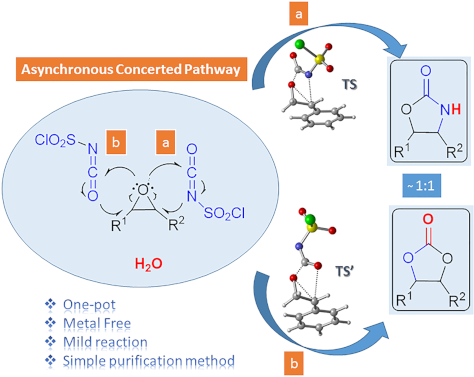
- . The further investigation of the potential energy surfaces associated with two possible channels leading to oxazolidinones and five-membered cyclic carbonates disclosed that the cycloaddition reaction proceeds via an asynchronous concerted mechanism in gas phase and in DCM. Keywords: chlorosulfonyl
- N4 onto the less sterically encumbered C1 atom of the epoxide 7f forming intermediate 11. Optimized geometries of transition structures are depicted in Figure 1. Our calculated results for the reaction indicate 17.4 kcal/mol (gas phase) and 26.7 kcal/mol (in DCM) preference for the TS1 over the TS1
- energy profiles connecting each transition state to the two associated minima. The effect of the solvent environment on the reaction pathways has been taken into account by single-point energy calculations on the gas-phase stationary points using a polarizable continuum model (PCM) [64] at M06-2X/6-31+G

Graphical Abstract

Scheme 1: Oxazolidinone (1), five-membered cyclic carbonate (2) and some important compounds containing an ox...

Scheme 2: Proposed mechanisms by Keshava Murthy and Dhar [41] and De Meijere and co-workers [42].

Figure 1: Possible pathways for the formation of oxazolidinone intermediates 10 and 11. Optimized transition ...

Figure 2: Potential energy profile related to the formation of oxazolidinone intermediates 10 and 11 at the P...

Figure 3: IRC calculated for the formation of (a) 10 and (b) 11 at M06-2X/6-31+G(d,p) level. I-1, I-15, I-35, ...

Figure 4: Optimized geometries for the stationary points for the formation of 10 at PCM(DCM)/M06-2X/6-31+G(d,...

Scheme 3: Proposed mechanisms for the formation of oxazolidinone 9f.

Figure 5: Potential energy profiles for paths 1a (blue), 1b (red), 2 (green) and relative Gibbs free energies...

Figure 6: Optimized geometries for the stationary points of path 1b at PCM(DCM)/M06-2X/6-31+G(d,p)//M06-2X/6-...

Scheme 4: Proposed mechanism for the formation of five-membered cyclic carbonate 8f.

Figure 7: Potential energy profile and relative Gibbs free energies (kcal/mol) in DCM related to the formatio...

Figure 8: Optimized geometries for the stationary points of step 1 for the formation of 16 at PCM(DCM)/M06-2X...

Figure 9: Optimized geometries for the stationary points of step 2 for the formation of 17 at PCM(DCM)/M06-2X...

Figure 10: Optimized geometries for the stationary points of step 3 for the formation of PC8 at PCM(DCM)/M06-2...
Heterogeneous photocatalysis in flow chemical reactors
- Christopher G. Thomson,
- Ai-Lan Lee and
- Filipe Vilela
Beilstein J. Org. Chem. 2020, 16, 1495–1549, doi:10.3762/bjoc.16.125


Graphical Abstract

Figure 1: A) Bar chart of the publications per year for the topics “Photocatalysis” (49,662 instances) and “P...

Figure 2: A) Professor Giacomo Ciamician and Dr. Paolo Silber on their roof laboratory at the University of B...

Scheme 1: PRC trifluoromethylation of N-methylpyrrole (1) using hazardous gaseous CF3I safely in a flow react...

Figure 3: A) Unit cells of the three most common crystal structures of TiO2: rutile, brookite, and anatase. R...

Figure 4: Illustration of the key semiconductor photocatalysis events: 1) A photon with a frequency exceeding...

Figure 5: Photocatalytic splitting of water by oxygen vacancies on a TiO2(110) surface. Reprinted with permis...

Figure 6: Proposed adsorption modes of A) benzene, B) chlorobenzene, C) toluene, D) phenol, E) anisole, and F...

Figure 7: Structures of the sulfonate-containing organic dyes RB5 (3) and MX-5B (4) and the adsorption isothe...

Figure 8: Idealised triclinic unit cell of a g-C3N4 type polymer, displaying possible hopping transport scena...

Figure 9: Idealised structure of a perfect g-C3N4 sheet. The central unit highlighted in red represents one t...

Figure 10: Timeline of the key processes of charge transport following the photoexcitation of g-C3N4, leading ...

Scheme 2: Photocatalytic bifunctionalisation of heteroarenes using mpg-C3N4, with the selected examples 5 and ...

Figure 11: A) Structure of four linear conjugated polymer photocatalysts for hydrogen evolution, displaying th...

Figure 12: Graphical representation of the common methods used to immobilise molecular photocatalysts (PC) ont...

Figure 13: Wireless light emitter-supported TiO2 (TiO2@WLE) HPCat spheres powered by resonant inductive coupli...

Figure 14: Graphical representation of zinc–perylene diimide (Zn-PDI) supramolecular assembly photocatalysis v...

Scheme 3: Upconversion of NIR photons to the UV frequency by NaYF4:Yb,Tm nanocrystals sequentially coated wit...

Figure 15: Types of reactors employed in heterogeneous photocatalysis in flow. A) Fixed bed reactors and the s...

Figure 16: Electrochemical potential of common semiconductor, transition metal, and organic dye-based photocat...

Scheme 4: Possible mechanisms of an immobilised molecular photoredox catalyst by oxidative or reductive quenc...

Scheme 5: Scheme of the CMB-C3N4 photocatalytic decarboxylative fluorination of aryloxyacetic acids, with the...

Scheme 6: Scheme of the g-C3N4 photocatalytic desilylative coupling reaction in flow and proposed mechanism [208].

Scheme 7: Proposed mechanism of the radical cyclisation of unsaturated alkyl 2-bromo-1,3-dicarbonyl compounds...

Scheme 8: N-alkylation of benzylamine and schematic of the TiO2-coated microfluidic device [213].

Scheme 9: Proposed mechanism of the Pt@TiO2 photocatalytic deaminitive cyclisation of ʟ-lysine (23) to ʟ-pipe...

Scheme 10: A) Proposed mechanism for the photocatalytic oxidation of phenylboronic acid (24). B) Photos and SE...

Scheme 11: Proposed mechanism for the DA-CMP3 photocatalytic aza-Henry reaction performed in a continuous flow...

Scheme 12: Proposed mechanism for the formation of the cyclic product 32 by TiO2-NC HPCats in a slurry flow re...

Scheme 13: Reaction scheme for the photocatalytic synthesis of homo and hetero disulfides in flow and scope of...

Scheme 14: Reaction scheme for the MoOx/TiO2 HPCat oxidation of cyclohexane (34) to benzene. The graph shows t...

Scheme 15: Proposed mechanism of the TiO2 HPC heteroarene C–H functionalisation via aryl radicals generated fr...

Scheme 16: Scheme of the oxidative coupling of benzylamines with the HOTT-HATN HPCat and selected examples of ...

Scheme 17: Photocatalysis oxidation of benzyl alcohol (40) to benzaldehyde (41) in a microflow reactor coated ...

Figure 17: Mechanisms of Dexter and Forster energy transfer.

Scheme 18: Continuous flow process for the isomerisation of alkenes with an ionic liquid-immobilised photocata...

Scheme 19: Singlet oxygen synthetic step in the total synthesis of canataxpropellane [265].

Scheme 20: Scheme and proposed mechanism of the singlet oxygen photosensitisation by CMP_X HPCats, with the st...

Scheme 21: Structures of CMP HPCat materials applied by Vilela and co-workers for the singlet oxygen photosens...

Scheme 22: Polyvinylchloride resin-supported TDCPP photosensitisers applied for singlet oxygen photosensitisat...

Scheme 23: Structure of the ionically immobilised TPP photosensitiser on amberlyst-15 ion exchange resins (TPP...

Scheme 24: Photosensitised singlet oxygen oxidation of citronellol (46) in scCO2, with automatic phase separat...

Scheme 25: Schematic of PS-Est-BDP-Cl2 being applied for singlet oxygen photosensitisation in flow. A) Pseudo-...

Scheme 26: Reaction scheme of the singlet oxygen oxidation of furoic acid (54) using a 3D-printed microfluidic...

Figure 18: A) Photocatalytic bactericidal mechanism by ROS oxidative cleavage of membrane lipids (R = H, amino...

Figure 19: A) Suggested mechanisms for the aqueous pollutant degradation by TiO2 in a slurry flow reactor [284-287]. B)...

Figure 20: Schematic of the flow system used for the degradation of aqueous oxytetracycline (56) solutions [215]. M...

Scheme 27: Degradation of a salicylic acid (57) solution by a coupled solar photoelectro-Fenton (SPEF) process...

Figure 21: A) Schematic flow diagram using the TiO2-coated NETmix microfluidic device for an efficient mass tr...
Activated carbon as catalyst support: precursors, preparation, modification and characterization
- Melanie Iwanow,
- Tobias Gärtner,
- Volker Sieber and
- Burkhard König
Beilstein J. Org. Chem. 2020, 16, 1188–1202, doi:10.3762/bjoc.16.104

- . Different methods can be used for the measurements. The volumetric method with determination of the gas removed from the gas phase and the gravimetric method, where the uptake of the gas by the adsorbent is determined by the increase in mass. In addition, static or dynamic techniques are available for the
- -containing surface groups on the activated carbon materials. They could observe that gas phase oxidation led to a higher amount of mainly hydroxy and carbonyl groups, whereas liquid phase treatment with nitric acid results in an increase of carboxylic acid groups [110]. Lillo-Ródenas et al. used TPD for the

Graphical Abstract

Figure 1: Experimental setup of ultrasonic spray pyrolysis. Reprinted with permission from [95], copyright 2006 T...

Figure 2: Overview of nitrogen-containing functional groups on the surface of activated carbons. Scheme was d...
A cyclopeptide and three oligomycin-class polyketides produced by an underexplored actinomycete of the genus Pseudosporangium
- Shun Saito,
- Kota Atsumi,
- Tao Zhou,
- Keisuke Fukaya,
- Daisuke Urabe,
- Naoya Oku,
- Md. Rokon Ul Karim,
- Hisayuki Komaki and
- Yasuhiro Igarashi
Beilstein J. Org. Chem. 2020, 16, 1100–1110, doi:10.3762/bjoc.16.97

- structures 1a and 1b The conformational search on structure 1a began by applying 100,000 steps of the Monte-Carlo Multiple Minimum (MCMM) method with PRCG energy minimization using the OPLS3e force field (gas phase) to obtain 20 conformational isomers within 5.0 kcal/mol from the minimum energy conformer

Graphical Abstract

Figure 1: Structures of pseudosporamide (1) and pseudosporamicins A–C (2–4).

Figure 2: COSY, key HMBC and ROESY correlations of pseudosporamide (1).

Figure 3: 1H NMR ΔδS−R values for PGME amides 5a and 5b obtained from compound 1.

Figure 4: The opposite axial chirality around the biaryl C-6–C-7'' bond influenced by the C-2 configuration i...

Figure 5: The experimental and calculated ECD spectra in MeCN.

Figure 6: COSY, key HMBC and NOESY correlations of compound 2.

Figure 7: NOESY correlations for the spiroacetal moiety of compound 2.

Figure 8: Selected examples of oligomycin-class metabolites from actinomycetes.
Synthesis of 4-(2-fluorophenyl)-7-methoxycoumarin: experimental and computational evidence for intramolecular and intermolecular C–F···H–C bonds
- Vuyisa Mzozoyana,
- Fanie R. van Heerden and
- Craig Grimmer
Beilstein J. Org. Chem. 2020, 16, 190–199, doi:10.3762/bjoc.16.22

- H3···19F coupling (Figure 3). Evidence of a HOESY interaction between H5···19F and H3···19F indicates that neither the H3···19F nor the H5···19F interaction limits the C4–C1′ bond rotation. The geometry of coumarin 6 (single molecule, gas phase) was optimized using the B3LYP functional and the 6-311G
- angle Φ C2’–C1’–C4–C4a (°). Short contacts within the single-crystal X-ray structure of coumarin 6. Synthesis of 4-(2-fluorophenyl)-7-methoxycoumarin (6). Experimental and theoretical (gas phase) 1H and 13C chemical shift (δ) for atoms within six bonds from fluorine for coumarin 6 and RSMD values

Graphical Abstract

Scheme 1: Synthesis of 4-(2-fluorophenyl)-7-methoxycoumarin (6).

Figure 1: 1H NMR spectra for the “aromatic” region of coumarin 6; comparison of 1H spectrum and 1H-{19F} spec...

Figure 2: 13C NMR spectra for coumarin 5 and 6; showing the splitting of the signal corresponding to C5.

Figure 3: 19F,1H-HOESY NMR spectrum for coumarin 6 illustrating two through-space interactions.

Figure 4: Superposition of single-crystal X-ray structure (red) and DFT-optimized structure (green); RMSD 0.3...

Figure 5: DFT-optimized structure for coumarin (6).

Figure 6: Plots of relative energy (black trace, no units), interatomic distance F–H5 (red trace, Å), interat...

Figure 7: Short contacts within the single-crystal X-ray structure of coumarin 6.
The reaction of arylmethyl isocyanides and arylmethylamines with xanthate esters: a facile and unexpected synthesis of carbamothioates
- Narasimhamurthy Rajeev,
- Toreshettahally R. Swaroop,
- Ahmad I. Alrawashdeh,
- Shofiur Rahman,
- Abdullah Alodhayb,
- Seegehalli M. Anil,
- Kuppalli R. Kiran,
- Chandra,
- Paris E. Georghiou,
- Kanchugarakoppal S. Rangappa and
- Maralinganadoddi P. Sadashiva
Beilstein J. Org. Chem. 2020, 16, 159–167, doi:10.3762/bjoc.16.18

- with Gaussian 09 [36]. The HF/6-31G(d) level of theory in the gas phase was only used to locate the transition state geometries. An intrinsic reaction coordinate (IRC) analysis was conducted for each transition state studied in this work to confirm that the transition states were associated with the

Graphical Abstract

Scheme 1: Synthesis of carbamothioates from xanthate esters and benzyl isocyanides.

Figure 1: Substrate scope for the synthesis of carbamothioates. Reaction conditions for methods A and B: sodi...

Figure 2: ORTEP diagram of O-benzyl (4-fluorobenzyl)carbamothioate (4c).

Figure 3: Rotamers of thionocarbamates 4 (top) and computer-minimized structures of 4c (bottom).

Scheme 2: Proposed general reaction mechanism for the formation of carbamothioates (e.g., 4a) from xanthate e...

Figure 4: Optimized geometries of the reactants, transition states, intermediates, and products of the propos...

Figure 5: Relative energies of the reactants, transition states (TS1–TS3), and intermediates (Int1–Int3) of t...