Search results
Search for "safe" in Full Text gives 201 result(s) in Beilstein Journal of Organic Chemistry. Showing first 200.
Towards new NIR dyes for free radical photopolymerization processes
- Haifaa Mokbel,
- Guillaume Noirbent,
- Didier Gigmes,
- Frédéric Dumur and
- Jacques Lalevée
Beilstein J. Org. Chem. 2021, 17, 2067–2076, doi:10.3762/bjoc.17.133

- and safe near-infrared (NIR) light is still the subject of intense research efforts but remains a huge challenge due to the associated low photon energy (wavelength from 0.78 to 2.5 µm). In this study, a series of 17 NIR dyes mainly based on a well-established cyanine scaffold is proposed. Remarkably
- ][4][5][6][7][8]. In this context, the use of NIR light is very attractive, i.e., such a long wavelength is quite safe and characterized by an excellent penetration in materials. Interestingly, NIR curing technology exhibit several advantages: i) an efficient process: a high polymerization rate

Graphical Abstract

Scheme 1: Investigated NIR dyes.

Scheme 2: Other used chemicals.

Scheme 3: Synthetic routes to compounds Ca, Cb, and CNa.

Scheme 4: Synthetic routes to CI1, CI3, CI4, and CI6–CI9.

Scheme 5: The metathesis reaction enabling the formation of “soft” salts CBPh1-CBPh4.

Figure 1: Visible–NIR spectra of NIR dyes in ACN. A) (1) CBPh1, (2) CBPh2, (3) CBPh3, (4) CBPh4, (5) Ca, (6) ...

Figure 2: Photopolymerization profiles of PETIA monomer under air (acrylate functions conversion vs irradiati...

Figure 3: Photopolymerization profiles of PETIA monomer under air (acrylate functions conversion vs irradiati...

Scheme 6: Pictures of polymers obtained for a thickness of 1.4 mm, using a NIR dye/iod/amine 0.1:3:2, %w/w/w ...

Scheme 7: Proposed mechanism for the photochemical reactivity of NIR dyes in a three-component PIS.

Figure 4: A) Photopolymerization profiles of PETIA/epoxy blend 1:1, w/w under air (acrylate and epoxy functio...
Development of N-F fluorinating agents and their fluorinations: Historical perspective
- Teruo Umemoto,
- Yuhao Yang and
- Gerald B. Hammond
Beilstein J. Org. Chem. 2021, 17, 1752–1813, doi:10.3762/bjoc.17.123

- agents for many years. However, these reagents have significant risks for safe handling. Although XeF2 [15] was considered as a safer alternative, it is expensive because of the scarcity of Xe in nature. The appearance of the safe and easy-to-handle N-F fluorinating agents described in this review have

Graphical Abstract

Scheme 1: Fluorination with N-F amine 1-1.

Scheme 2: Preparation of N-F amine 1-1.

Scheme 3: Reactions of N-F amine 1-1.

Scheme 4: Synthesis of N-F perfluoroimides 2-1 and 2-2.

Scheme 5: Synthesis of 1-fluoro-2-pyridone (3-1).

Scheme 6: Fluorination with 1-fluoro-2-pyridone (3-1).

Figure 1: Synthesis of N-F sulfonamides 4-1a–g.

Scheme 7: Fluorination with N-F reagent 4-1b,c,f.

Scheme 8: Fluorination of alkenyllithiums with N-F 4-1h.

Scheme 9: Synthesis of N-fluoropyridinium triflate (5-4a).

Scheme 10: Synthetic methods for N-F-pyridinium salts.

Figure 2: Synthesis of various N-fluoropyridinium salts. Note: athis yield was the one by the improved method...

Scheme 11: Fluorination power order of N-fluoropyridinium salts.

Scheme 12: Fluorinations with N-F salts 5-4.

Scheme 13: Fluorination of Corey lactone 5-7 with N-F-bis(methoxymethyl) salt 5-4l.

Scheme 14: Fluorination with NFPy.

Scheme 15: Synthesis of the N-F reagent, N-fluoroquinuclidinium fluoride (6-1).

Scheme 16: Fluorinations achieved with N-F fluoride 6-1.

Scheme 17: Synthesis of N-F imides 7-1a–g.

Scheme 18: Fluorination with (CF3SO2)2NF, 7-1a.

Scheme 19: Fluorination reactions of various substrates with 7-1a.

Scheme 20: Synthesis of N-F triflate 8-1.

Scheme 21: Synthesis of chiral N-fluoro sultams 9-1 and 9-2.

Scheme 22: Fluorination with chiral N-fluoro sultams 9-1 and 9-2.

Scheme 23: Synthesis of saccharin-derived N-fluorosultam 10-2.

Scheme 24: Fluorination with N-fluorosultam 10-2.

Scheme 25: Synthesis of N-F reagent 11-2.

Scheme 26: Fluorination with N-F reagent 11-2.

Scheme 27: Synthesis and reaction of N-fluorolactams 12-1.

Scheme 28: Synthesis of NFOBS 13-2.

Scheme 29: Fluorination with NFOBS 13-2.

Scheme 30: Synthesis of NFSI (14-2).

Scheme 31: Fluorination with NFSI 14-2.

Scheme 32: Synthesis of N-fluorosaccharin (15-1) and N-fluorophthalimide (15-2).

Scheme 33: Synthesis of N-F salts 16-3.

Scheme 34: Fluorination with N-F salts 16-3.

Figure 3: Monofluorination with Selectfluor (16-3a).

Figure 4: Difluorination with Selectfluor (16-3a).

Scheme 35: Transfer fluorination of Selectfluor (16-3a).

Scheme 36: Fluorination of substrates with Selectfluor (16-3a).

Scheme 37: Synthesis of chiral N-fluoro-sultam 17-2.

Scheme 38: Asymmetric fluorination with chiral 17-2.

Figure 5: Synthesis of Zwitterionic N-fluoropyridinium salts 18-2a–h.

Scheme 39: Fluorinating power order of zwitterionic N-fluoropyridinium salts.

Scheme 40: Fluorination with zwitterionic 18-2.

Scheme 41: Activation of salt 18-2h with TfOH.

Scheme 42: Synthesis of NFTh, 19-2.

Scheme 43: Fluorination with NFTh, 19-2.

Scheme 44: Synthesis of 3-fluorobenzo-1,2,3-oxathiazin-4-one 2,2-dioxide (20-2).

Scheme 45: Fluorination with 20-2.

Scheme 46: Synthesis of N-F amide 21-3.

Scheme 47: Fluorination with N-F amide 21-2.

Scheme 48: Synthesis of N,N’-difluorodiazoniabicyclo[2.2.2]octane salts 22-1.

Scheme 49: One-pot synthesis of N,N’-difluoro-1,4-diazoniabicyclo[2.2.2]octane bistetrafluoroborate salt (22-1d...

Figure 6: Fluorination of anisole with 22-1a, d, e.

Scheme 50: Fluorination with N,N’-diF bisBF4 22-1d.

Scheme 51: Synthesis of bis-N-F reagents 23-1–5.

Scheme 52: Fluorination with 23-2, 4, 5.

Figure 7: Synthesis of N,N’-difluorobipyridinium salts 24-2.

Figure 8: Controlled fluorination of N,N’-diF 24-2.

Scheme 53: Fluorinating power of N,N’-diF salts 24-2 and N-F salt 5-4a.

Scheme 54: Fluorination reactions with SynfluorTM (24-2b).

Scheme 55: Additional fluorination reactions with SynfluorTM (24-2b).

Scheme 56: Synthesis of N-F 25-1.

Scheme 57: Fluorination of polycyclic aromatics with 25-1.

Scheme 58: Synthesis of 26-1 and dimethyl analog 26-2.

Scheme 59: Fluorination with reagents 26-1, 26-2, 1-1, and 26-3.

Scheme 60: Synthesis of N-F reagent 27-2.

Scheme 61: Synthesis of chiral N-F reagents 27-6.

Scheme 62: Synthesis of chiral N-F 27-7–9.

Scheme 63: Asymmetric fluorination with 27-6.

Scheme 64: Synthesis of chiral N-F reagents 28-3.

Scheme 65: Asymmetric fluorination with 28-3.

Scheme 66: Synthesis of chiral N-F reagents 28-7.

Figure 9: Asymmetric fluorination with 28-7.

Scheme 67: In situ formation of N-fluorinated cinchona alkaloids with SelectfluorTM.

Scheme 68: Asymmetric fluorination with N-F alkaloids formed in situ.

Scheme 69: Synthesis of N-fluorocinchona alkaloids with Selectfluor.

Scheme 70: Asymmetric fluorination with 30-1–4.

Scheme 71: Transfer fluorination from various N-F reagents.

Figure 10: Asymmetric fluorination of silyl enol ethers.

Scheme 72: Synthesis of N-fluoro salt 32-2.

Scheme 73: Reactivity of N-fluorotriazinium salt 32-2.

Scheme 74: Synthesis of bulky N-fluorobenzenesulfonimide NFBSI 33-3.

Scheme 75: Comparison of NFSI and NFBSI.

Scheme 76: Synthesis of p-substituted N-fluorobenzenesulfonimides 34-3.

Figure 11: Asymmetric fluorination with 34-3 and a chiral catalyst 34-4.

Scheme 77: 1,4-Fluoroamination with Selecfluor and a chiral catalyst.

Figure 12: Asymmetric fluoroamination with 35-5a, b.

Scheme 78: Synthesis of Selectfluor analogs 35-5a, b.

Scheme 79: Synthesis of chiral dicationic DABCO-based N-F reagents 36-5.

Scheme 80: Asymmetric fluorocyclization with chiral 36-5b.

Scheme 81: Synthesis of chiral 37-2a,b.

Scheme 82: Asymmetric fluorination with chiral 37-2a,b.

Scheme 83: Asymmetric fluorination with chiral 37-2b.

Scheme 84: Reaction of indene with chiral 37-2a,b.

Scheme 85: Synthesis of Me-NFSI, 38-2.

Scheme 86: Fluorination of active methine compounds with Me-NFSI.

Scheme 87: Fluorination of malonates with Me-NFSI.

Scheme 88: Fluorination of keto esters with Me-NFSI.

Scheme 89: Synthesis of N-F 39-3 derived from the ethylene-bridged Tröger’s base.

Scheme 90: Fluorine transfer from N-F 39-3.

Scheme 91: Fluorination with N-F 39-3.

Scheme 92: Synthesis of SelectfluorCN.

Scheme 93: Bistrifluoromethoxylation of alkenes using SelectfluorCN.

Figure 13: Synthesis of NFAS 41-2.

Scheme 94: Radical fluorination with different N-F reagents.

Scheme 95: Radical fluorination of alkenes with NFAS 41-2.

Scheme 96: Radical fluorination of alkenes with NFAS 41-2f.

Scheme 97: Decarboxylative fluorination with NFAS 41-2a,f.

Scheme 98: Fluorine plus detachment (FPD).

Figure 14: FPD values of representative N-F reagents in CH2Cl2 and CH3CN (in parentheses). Adapted with permis...

Scheme 99: N-F homolytic bond dissociation energy (BDE).

Figure 15: BDE values of representative N-F reagents in CH3CN. Adapted with permission from ref. [127]. Copyright 2...

Figure 16: Quantitative reactivity scale for popular N-F reagents. Adapted with permission from ref. [138], publish...

Scheme 100: SET and SN2 mechanisms.

Scheme 101: Radical clock reactions.

Scheme 102: Reaction of potassium enolate of citronellic ester with N-F reagents, 10-1, NFSI, and 8-1.

Scheme 103: Reaction of compound IV with Selectfluor (OTf) and NFSI.

Scheme 104: Reaction of TEMPO with Selecfluor.
A comprehensive review of flow chemistry techniques tailored to the flavours and fragrances industries
- Guido Gambacorta,
- James S. Sharley and
- Ian R. Baxendale
Beilstein J. Org. Chem. 2021, 17, 1181–1312, doi:10.3762/bjoc.17.90

- commercial flow reactors allow for the safe simulation of larger scale processes within the lab environment, facilitating and expediting the process optimisation experience. While some of the implications of the flow chemistry are more obvious than others, i.e., greener processes with potential cost

Graphical Abstract

Figure 1: Representative shares of the global F&F market (2018) segmented on their applications [1].

Figure 2: General structure of an international fragrance company [2].

Figure 3: The Michael Edwards fragrance wheel.

Figure 4: Examples of oriental (1–3), woody (4–7), fresh (8–10), and floral (11 and 12) notes.

Figure 5: A basic depiction of batch vs flow.

Scheme 1: Examples of reactions for which flow processing outperforms batch.

Scheme 2: Some industrially important aldol-based transformations.

Scheme 3: Biphasic continuous aldol reactions of acetone and various aldehydes.

Scheme 4: Aldol synthesis of 43 in flow using LiHMDS as the base.

Scheme 5: A semi-continuous synthesis of doravirine (49) involving a key aldol reaction.

Scheme 6: Enantioselective aldol reaction using 5-(pyrrolidin-2-yl)tetrazole (51) as catalyst in a microreact...

Scheme 7: Gröger's example of asymmetric aldol reaction in aqueous media.

Figure 6: Immobilised reagent column reactor types.

Scheme 8: Photoinduced thiol–ene coupling preparation of silica-supported 5-(pyrrolidin-2-yl)tetrazole 63 and...

Scheme 9: Continuous-flow approach for enantioselective aldol reactions using the supported catalyst 67.

Scheme 10: Ötvös’ employment of a solid-supported peptide aldol catalyst in flow.

Scheme 11: The use of proline tetrazole packed in a column for aldol reaction between cyclohexanone (65) and 2...

Scheme 12: Schematic diagram of an aminosilane-grafted Si-Zr-Ti/PAI-HF reactor for continuous-flow aldol and n...

Scheme 13: Continuous-flow condensation for the synthesis of the intermediate 76 to nabumetone (77) and Microi...

Scheme 14: Synthesis of ψ-Ionone (80) in continuous-flow via aldol condensation between citral (79) and aceton...

Scheme 15: Synthesis of β-methyl-ionones (83) from citral (79) in flow. The steps are separately described, an...

Scheme 16: Continuous-flow synthesis of 85 from 84 described by Gavriilidis et al.

Scheme 17: Continuous-flow scCO2 apparatus for the synthesis of 2-methylpentanal (87) and the self-condensed u...

Scheme 18: Chen’s two-step flow synthesis of coumarin (90).

Scheme 19: Pechmann condensation for the synthesis of 7-hydroxyxcoumarin (93) in flow. The setup extended to c...

Scheme 20: Synthesis of the dihydrojasmonate 35 exploiting nitro derivative proposed by Ballini et al.

Scheme 21: Silica-supported amines as heterogeneous catalyst for nitroaldol condensation in flow.

Scheme 22: Flow apparatus for the nitroaldol condensation of p-hydroxybenzaldehyde (102) to nitrostyrene 103 a...

Scheme 23: Nitroaldol reaction of 64 to 105 employing a quaternary ammonium functionalised PANF.

Scheme 24: Enantioselective nitroaldol condensation for the synthesis of 108 under flow conditions.

Scheme 25: Enatioselective synthesis of 1,2-aminoalcohol 110 via a copper-catalysed nitroaldol condensation.

Scheme 26: Examples of Knoevenagel condensations applied for fragrance components.

Scheme 27: Flow apparatus for Knoevenagel condensation described in 1989 by Venturello et al.

Scheme 28: Knoevenagel reaction using a coated multichannel membrane microreactor.

Scheme 29: Continuous-flow apparatus for Knoevenagel condensation employing sugar cane bagasse as support deve...

Scheme 30: Knoevenagel reaction for the synthesis of 131–135 in flow using an amine-functionalised silica gel. ...

Scheme 31: Continuous-flow synthesis of compound 137, a key intermediate for the synthesis of pregabalin (138)...

Scheme 32: Continuous solvent-free apparatus applied for the synthesis of compounds 140–143 using a TSE. Throu...

Scheme 33: Lewis et al. developed a spinning disc reactor for Darzens condensation of 144 and a ketone to furn...

Scheme 34: Some key industrial applications of conjugate additions in the F&F industry.

Scheme 35: Continuous-flow synthesis of 4-(2-hydroxyethyl)thiomorpholine 1,1-dioxide (156) via double conjugat...

Scheme 36: Continuous-flow system for Michael addition using CsF on alumina as the catalyst.

Scheme 37: Calcium chloride-catalysed asymmetric Michael addition using an immobilised chiral ligand.

Scheme 38: Continuous multistep synthesis for the preparation of (R)-rolipram (173). Si-NH2: primary amine-fun...

Scheme 39: Continuous-flow Michael addition using ion exchange resin Amberlyst® A26.

Scheme 40: Preparation of the heterogeneous catalyst 181 developed by Paixão et al. exploiting Ugi multicompon...

Scheme 41: Continuous-flow system developed by the Paixão’s group for the preparation of Michael asymmetric ad...

Scheme 42: Continuous-flow synthesis of nitroaldols catalysed by supported catalyst 184 developed by Wennemers...

Scheme 43: Heterogenous polystyrene-supported catalysts developed by Pericàs and co-workers.

Scheme 44: PANF-supported pyrrolidine catalyst for the conjugate addition of cyclohexanone (65) and trans-β-ni...

Scheme 45: Synthesis of (−)-paroxetine precursor 195 developed by Ötvös, Pericàs, and Kappe.

Scheme 46: Continuous-flow approach for the 5-step synthesis of (−)-oseltamivir (201) as devised by Hayashi an...

Scheme 47: Continuous-flow enzyme-catalysed Michael addition.

Scheme 48: Continuous-flow copper-catalysed 1,4 conjugate addition of Grignard reagents to enones. Reprinted w...

Scheme 49: A collection of commonly encountered hydrogenation reactions.

Figure 7: The ThalesNano H-Cube® continuous-flow hydrogenator.

Scheme 50: Chemoselective reduction of an α,β-unsaturated ketone using the H-Cube® reactor.

Scheme 51: Incorporation of Lindlar’s catalyst into the H-Cube® reactor for the reduction of an alkyne.

Scheme 52: Continuous-flow semi-hydrogenation of alkyne 208 to 209 using SACs with H-Cube® system.

Figure 8: The standard setups for tube-in-tube gas–liquid reactor units.

Scheme 53: Homogeneous hydrogenation of olefins using a tube-in-tube reactor setup.

Scheme 54: Recyclable heterogeneous flow hydrogenation system.

Scheme 55: Leadbeater’s reverse tube-in-tube hydrogenation system for olefin reductions.

Scheme 56: a) Hydrogenation using a Pd-immobilised microchannel reactor (MCR) and b) a representation of the i...

Scheme 57: Hydrogenation of alkyne 238 exploiting segmented flow in a Pd-immobilised capillary reactor.

Scheme 58: Continuous hydrogenation system for the preparation of cyrene (241) from (−)-levoglucosenone (240).

Scheme 59: Continuous hydrogenation system based on CSMs developed by Hornung et al.

Scheme 60: Chemoselective reduction of carbonyls (ketones over aldehydes) in flow.

Scheme 61: Continuous system for the semi-hydrogenation of 256 and 258, developed by Galarneau et al.

Scheme 62: Continuous synthesis of biodiesel fuel 261 from lignin-derived furfural acetone (260).

Scheme 63: Continuous synthesis of γ-valerolacetone (263) via CTH developed by Pineda et al.

Scheme 64: Continuous hydrogenation of lignin-derived biomass (products 265, 266, and 267) using a sustainable...

Scheme 65: Ru/C or Rh/C-catalysed hydrogenation of arene in flow as developed by Sajiki et al.

Scheme 66: Polysilane-immobilized Rh–Pt-catalysed hydrogenation of arenes in flow by Kobayashi et al.

Scheme 67: High-pressure in-line mixing of H2 for the asymmetric reduction of 278 at pilot scale with a 73 L p...

Figure 9: Picture of the PFR employed at Eli Lilly & Co. for the continuous hydrogenation of 278 [287]. Reprinted ...

Scheme 68: Continuous-flow asymmetric hydrogenation using Oppolzer's sultam 280 as chiral auxiliary.

Scheme 69: Some examples of industrially important oxidation reactions in the F&F industry. CFL: compact fluor...

Scheme 70: Gold-catalysed heterogeneous oxidation of alcohols in flow.

Scheme 71: Uozumi’s ARP-Pt flow oxidation protocol.

Scheme 72: High-throughput screening of aldehyde oxidation in flow using an in-line GC.

Scheme 73: Permanganate-mediated Nef oxidation of nitroalkanes in flow with the use of in-line sonication to p...

Scheme 74: Continuous-flow aerobic anti-Markovnikov Wacker oxidation.

Scheme 75: Continuous-flow oxidation of 2-benzylpyridine (312) using air as the oxidant.

Scheme 76: Continuous-flow photo-oxygenation of monoterpenes.

Scheme 77: A tubular reactor design for flow photo-oxygenation.

Scheme 78: Glucose oxidase (GOx)-mediated continuous oxidation of glucose using compressed air and the FFMR re...

Scheme 79: Schematic continuous-flow sodium hypochlorite/TEMPO oxidation of alcohols.

Scheme 80: Oxidation using immobilised TEMPO (344) was developed by McQuade et al.

Scheme 81: General protocol for the bleach/catalytic TBAB oxidation of aldehydes and alcohols.

Scheme 82: Continuous-flow PTC-assisted oxidation using hydrogen peroxide. The process was easily scaled up by...

Scheme 83: Continuous-flow epoxidation of cyclohexene (348) and in situ preparation of m-CPBA.

Scheme 84: Continuous-flow epoxidation using DMDO as oxidant.

Scheme 85: Mukayama aerobic epoxidation optimised in flow mode by the Favre-Réguillon group.

Scheme 86: Continuous-flow asymmetric epoxidation of derivatives of 359 exploiting a biomimetic iron catalyst.

Scheme 87: Continuous-flow enzymatic epoxidation of alkenes developed by Watts et al.

Scheme 88: Engineered multichannel microreactor for continuous-flow ozonolysis of 366.

Scheme 89: Continuous-flow synthesis of the vitamin D precursor 368 using multichannel microreactors. MFC: mas...

Scheme 90: Continuous ozonolysis setup used by Kappe et al. for the synthesis of various substrates employing ...

Scheme 91: Continuous-flow apparatus for ozonolysis as developed by Ley et al.

Scheme 92: Continuous-flow ozonolysis for synthesis of vanillin (2) using a film-shear flow reactor.

Scheme 93: Examples of preparative methods for ajoene (386) and allicin (388).

Scheme 94: Continuous-flow oxidation of thioanisole (389) using styrene-based polymer-supported peroxytungstat...

Scheme 95: Continuous oxidation of thiosulfinates using Oxone®-packed reactor.

Scheme 96: Continuous-flow electrochemical oxidation of thioethers.

Scheme 97: Continuous-flow oxidation of 400 to cinnamophenone (235).

Scheme 98: Continuous-flow synthesis of dehydrated material 401 via oxidation of methyl dihydrojasmonate (33).

Scheme 99: Some industrially important transformations involving Grignard reagents.

Scheme 100: Grachev et al. apparatus for continuous preparation of Grignard reagents.

Scheme 101: Example of fluidized Mg bed reactor with NMR spectrometer as on-line monitoring system.

Scheme 102: Continuous-flow synthesis of Grignard reagents and subsequent quenching reaction.

Figure 10: Membrane-based, liquid–liquid separator with integrated pressure control [52]. Adapted with permission ...

Scheme 103: Continuous-flow synthesis of 458, an intermediate to fluconazole (459).

Scheme 104: Continuous-flow synthesis of ketones starting from benzoyl chlorides.

Scheme 105: A Grignard alkylation combining CSTR and PFR technologies with in-line infrared reaction monitoring....

Scheme 106: Continuous-flow preparation of 469 from Grignard addition of methylmagnesium bromide.

Scheme 107: Continuous-flow synthesis of Grignard reagents 471.

Scheme 108: Preparation of the Grignard reagent 471 using CSTR and the continuous process for synthesis of the ...

Scheme 109: Continuous process for carboxylation of Grignard reagents in flow using tube-in-tube technology.

Scheme 110: Continuous synthesis of propargylic alcohols via ethynyl-Grignard reagent.

Scheme 111: Silica-supported catalysed enantioselective arylation of aldehydes using Grignard reagents in flow ...

Scheme 112: Acid-catalysed rearrangement of citral and dehydrolinalool derivatives.

Scheme 113: Continuous stilbene isomerisation with continuous recycling of photoredox catalyst.

Scheme 114: Continuous-flow synthesis of compound 494 as developed by Ley et al.

Scheme 115: Selected industrial applications of DA reaction.

Scheme 116: Multistep flow synthesis of the spirocyclic structure 505 via employing DA cycloaddition.

Scheme 117: Continuous-flow DA reaction developed in a plater flow reactor for the preparation of the adduct 508...

Scheme 118: Continuous-flow DA reaction using a silica-supported imidazolidinone organocatalyst.

Scheme 119: Batch vs flow for the DA reaction of (cyclohexa-1,5-dien-1-yloxy)trimethylsilane (513) with acrylon...

Scheme 120: Continuous-flow DA reaction between 510 and 515 using a shell-core droplet system.

Scheme 121: Continuous-flow synthesis of bicyclic systems from benzyne precursors.

Scheme 122: Continuous-flow synthesis of bicyclic scaffolds 527 and 528 for further development of potential ph...

Scheme 123: Continuous-flow inverse-electron hetero-DA reaction to pyridine derivatives such as 531.

Scheme 124: Comparison between batch and flow for the synthesis of pyrimidinones 532–536 via retro-DA reaction ...

Scheme 125: Continuous-flow coupled with ultrasonic system for preparation of ʟ-ascorbic acid derivatives 539 d...

Scheme 126: Two-step continuous-flow synthesis of triazole 543.

Scheme 127: Continuous-flow preparation of triazoles via CuAAC employing 546-based heterogeneous catalyst.

Scheme 128: Continuous-flow synthesis of compounds 558 through A3-coupling and 560 via AgAAC both employing the...

Scheme 129: Continuous-flow photoinduced [2 + 2] cycloaddition for the preparation of bicyclic derivatives of 5...

Scheme 130: Continuous-flow [2 + 2] and [5 + 2] cycloaddition on large scale employing a flow reactor developed...

Scheme 131: Continuous-flow preparation of the tricyclic structures 573 and 574 starting from pyrrole 570 via [...

Scheme 132: Continuous-flow [2 + 2] photocyclization of cinnamates.

Scheme 133: Continuous-flow preparation of cyclobutane 580 on a 5-plates photoreactor.

Scheme 134: Continuous-flow [2 + 2] photocycloaddition under white LED lamp using heterogeneous PCN as photocat...

Figure 11: Picture of the parallel tube flow reactor (PTFR) "The Firefly" developed by Booker-Milburn et al. a...

Scheme 135: Continuous-flow acid-catalysed [2 + 2] cycloaddition between silyl enol ethers and acrylic esters.

Scheme 136: Continuous synthesis of lactam 602 using glass column reactors.

Scheme 137: In situ generation of ketenes for the Staudinger lactam synthesis developed by Ley and Hafner.

Scheme 138: Application of [2 + 2 + 2] cycloadditions in flow employed by Ley et al.

Scheme 139: Examples of FC reactions applied in F&F industry.

Scheme 140: Continuous-flow synthesis of ibuprofen developed by McQuade et al.

Scheme 141: The FC acylation step of Jamison’s three-step ibuprofen synthesis.

Scheme 142: Synthesis of naphthalene derivative 629 via FC acylation in microreactors.

Scheme 143: Flow system for rapid screening of catalysts and reaction conditions developed by Weber et al.

Scheme 144: Continuous-flow system developed by Buorne, Muller et al. for DSD optimisation of the FC acylation ...

Scheme 145: Continuous-flow FC acylation of alkynes to yield β-chlorovinyl ketones such as 638.

Scheme 146: Continuous-flow synthesis of tonalide (619) developed by Wang et al.

Scheme 147: Continuous-flow preparation of acylated arene such as 290 employing Zr4+-β-zeolite developed by Kob...

Scheme 148: Flow system applied on an Aza-FC reaction catalysed by the thiourea catalyst 648.

Scheme 149: Continuous hydroformylation in scCO2.

Scheme 150: Two-step flow synthesis of aldehyde 655 through a sequential Heck reaction and subsequent hydroform...

Scheme 151: Single-droplet (above) and continuous (below) flow reactors developed by Abolhasani et al. for the ...

Scheme 152: Continuous hydroformylation of 1-dodecene (655) using a PFR-CSTR system developed by Sundmacher et ...

Scheme 153: Continuous-flow synthesis of the aldehyde 660 developed by Eli Lilly & Co. [32]. Adapted with permissio...

Scheme 154: Continuous asymmetric hydroformylation employing heterogenous catalst supported on carbon-based sup...

Scheme 155: Examples of acetylation in F&F industry: synthesis of bornyl (S,R,S-664) and isobornyl (S,S,S-664) ...

Scheme 156: Continuous-flow preparation of bornyl acetate (S,R,S-664) employing the oscillating flow reactor.

Scheme 157: Continuous-flow synthesis of geranyl acetate (666) from acetylation of geraniol (343) developed by ...

Scheme 158: 12-Ttungstosilicic acid-supported silica monolith-catalysed acetylation in flow.

Scheme 159: Continuous-flow preparation of cyclopentenone 676.

Scheme 160: Two-stage synthesis of coumarin (90) via acetylation of salicylaldehyde (88).

Scheme 161: Intensification process for acetylation of 5-methoxytryptamine (677) to melatonin (678) developed b...

Scheme 162: Examples of macrocyclic musky odorants both natural (679–681) and synthetic (682 and 683).

Scheme 163: Flow setup combined with microwave for the synthesis of macrocycle 686 via RCM.

Scheme 164: Continuous synthesis of 2,5-dihydro-1H-pyrroles via ring-closing metathesis.

Scheme 165: Continuous-flow metathesis of 485 developed by Leadbeater et al.

Figure 12: Comparison between RCM performed using different routes for the preparation of 696. On the left the...

Scheme 166: Continuous-flow RCM of 697 employed the solid-supported catalyst 698 developed by Grela, Kirschning...

Scheme 167: Continuous-flow RORCM of cyclooctene employing the silica-absorbed catalyst 700.

Scheme 168: Continuous-flow self-metathesis of methyl oleate (703) employing SILP catalyst 704.

Scheme 169: Flow apparatus for the RCM of 697 using a nanofiltration membrane for the recovery and reuse of the...

Scheme 170: Comparison of loadings between RCMs performed with different routes for the synthesis of 709.
Nitroalkene reduction in deep eutectic solvents promoted by BH3NH3
- Chiara Faverio,
- Monica Fiorenza Boselli,
- Patricia Camarero Gonzalez,
- Alessandra Puglisi and
- Maurizio Benaglia
Beilstein J. Org. Chem. 2021, 17, 1041–1047, doi:10.3762/bjoc.17.83

- safe as well as economically and environmentally sustainable alternative to the traditional organic solvents. Here, we report the combination of an atom-economic, very convenient and inexpensive reagent, such as BH3NH3, with bio-based eutectic mixtures as biorenewable solvents in the synthesis of
- whole research community concerned with the concept of a circular economy [3]. In this context, deep eutectic solvents (DESs) have attracted an increasing attention as green, safe, economically and environmentally sustainable alternative to the traditional organic solvents [4]. They are combinations of
- materials that can be used to form eutectic mixtures offers an incredibly high variety of combinations to generate new, safe and biodegradable DESs [5]. Another fundamental principle of green chemistry is the atom economy concept. In this context, ammonia borane (AB) is receiving increasing attention as

Graphical Abstract

Scheme 1: AB-mediated reductions of nitrostyrenes 3a–h.

Scheme 2: AB-mediated reductions of nitrostyrenes 1, 3a, and 3c using DESs B and D.

Scheme 3: AB-mediated reductions of nitroalkenes 5a–f.

Scheme 4: Recovery and recycling experiments in the AB-mediated reduction of nitrostyrene 3h to afford nitroa...
Synthetic accesses to biguanide compounds
- Oleksandr Grytsai,
- Cyril Ronco and
- Rachid Benhida
Beilstein J. Org. Chem. 2021, 17, 1001–1040, doi:10.3762/bjoc.17.82

- biguanides. This pathway is particularly convenient as cyanoguanidines are readily available, inexpensive, and safe [32]. Moreover, this reaction occurs with full atom economy and provides the desired biguanides with fairly high yields. A prior step of substituted cyanoguanidine preparation gives access to

Graphical Abstract

Figure 1: Tautomeric forms of biguanide.

Figure 2: Illustrations of neutral, monoprotonated, and diprotonated structures biguanide.

Figure 3: The main approaches for the synthesis of biguanides. The core structure is obtained via the additio...

Scheme 1: The three main preparations of biguanides from cyanoguanidine.

Scheme 2: Synthesis of butylbiguanide using CuCl2 [16].

Scheme 3: Synthesis of biguanides by the direct fusion of cyanoguanidine and amine hydrochlorides [17,18].

Scheme 4: Synthesis of ethylbiguanide and phenylbiguanide as reported by Smolka and Friedreich [14].

Scheme 5: Synthesis of arylbiguanides through the reaction of cyanoguanidine with anilines in water [19].

Scheme 6: Synthesis of aryl- and alkylbiguanides by adaptations of Cohn’s procedure [20,21].

Scheme 7: Microwave-assisted synthesis of N1-aryl and -dialkylbiguanides [22,23].

Scheme 8: Synthesis of aryl- and alkylbiguanides by trimethylsilyl activation [24,26].

Scheme 9: Synthesis of phenformin analogs by TMSOTf activation [27].

Scheme 10: Synthesis of N1-(1,2,4-triazolyl)biguanides [28].

Scheme 11: Synthesis of 2-guanidinobenzazoles by addition of ortho-substituted anilines to cyanoguanidine [30,32] and...

Scheme 12: Synthesis of 2,4-diaminoquinazolines by the addition of 2-cyanoaniline to cyanoguanidine and from 3...

Scheme 13: Reactions of anthranilic acid and 2-mercaptobenzoic acid with cyanoguanidine [24,36,37].

Scheme 14: Synthesis of disubstituted biguanides with Cu(II) salts [38].

Scheme 15: Synthesis of an N1,N2,N5-trisubstituted biguanide by fusion of an amine hydrochloride and 2-cyano-1...

Scheme 16: Synthesis of N1,N5-disubstituted biguanides by the addition of anilines to cyanoguanidine derivativ...

Scheme 17: Microwave-assisted additions of piperazine and aniline hydrochloride to substituted cyanoguanidines ...

Scheme 18: Synthesis of N1,N5-alkyl-substituted biguanides by TMSOTf activation [27].

Scheme 19: Additions of oxoamines hydrochlorides to dimethylcyanoguanidine [49].

Scheme 20: Unexpected cyclization of pyridylcyanoguanidines under acidic conditions [50].

Scheme 21: Example of industrial synthesis of chlorhexidine [51].

Scheme 22: Synthesis of symmetrical N1,N5-diarylbiguanides from sodium dicyanamide [52,53].

Scheme 23: Synthesis of symmetrical N1,N5-dialkylbiguanides from sodium dicyanamide [54-56].

Scheme 24: Stepwise synthesis of unsymmetrical N1,N5-trisubstituted biguanides from sodium dicyanamide [57].

Scheme 25: Examples for the synthesis of unsymmetrical biguanides [58].

Scheme 26: Examples for the synthesis of an 1,3-diaminobenzoquinazoline derivative by the SEAr cyclization of ...

Scheme 27: Major isomers formed by the SEAr cyclization of symmetric biguanides derived from 2- and 3-aminophe...

Scheme 28: Lewis acid-catalyzed synthesis of 8H-pyrrolo[3,2-g]quinazoline-2,4-diamine [63].

Scheme 29: Synthesis of [1,2,4]oxadiazoles by the addition of hydroxylamine to dicyanamide [49,64].

Scheme 30: Principle of “bisamidine transfer” and analogy between the reactions with N-amidinopyrazole and N-a...

Scheme 31: Representative syntheses of N-amidino-amidinopyrazole hydrochloride [68,69].

Scheme 32: First examples of biguanide syntheses using N-amidino-amidinopyrazole [66].

Scheme 33: Example of “biguanidylation” of a hydrazide substrate [70].

Scheme 34: Example for the synthesis of biguanides using S-methylguanylisothiouronium iodide as “bisamidine tr...

Scheme 35: Synthesis of N-substituted N1-cyano-S-methylisothiourea precursors.

Scheme 36: Addition routes on N1-cyano-S-methylisothioureas.

Scheme 37: Synthesis of an hydroxybiguanidine from N1-cyano-S-methylisothiourea [77].

Scheme 38: Synthesis of an N1,N2,N3,N4,N5-pentaarylbiguanide from the corresponding triarylguanidine and carbo...

Scheme 39: Reactions of N,N,N’,N’-tetramethylguanidine (TMG) with carbodiimides to synthesize hexasubstituted ...

Scheme 40: Microwave-assisted addition of N,N,N’,N’-tetramethylguanidine to carbodiimides [80].

Scheme 41: Synthesis of N1-aryl heptasubstituted biguanides via a one-pot biguanide formation–copper-catalyzed ...

Scheme 42: Formation of 1,2-dihydro-1,3,5-triazine derivatives by the reaction of guanidine with excess carbod...

Scheme 43: Plausible mechanism for the spontaneous cyclization of triguanides [82].

Scheme 44: a) Formation of mono- and disubstituted (iso)melamine derivatives by the reaction of biguanides and...

Scheme 45: Reactions of 2-aminopyrimidine with carbodiimides to synthesize 2-guanidinopyrimidines as “biguanid...

Scheme 46: Non-catalyzed alternatives for the addition of 2-aminopyrimidine derivatives to carbodiimides. A) h...

Scheme 47: Addition of guanidinomagnesium halides to substituted cyanamides [90].

Scheme 48: Microwave-assisted synthesis of [11C]metformin by the reaction of 11C-labelled dimethylcyanamide an...

Scheme 49: Formation of 4-amino-6-dimethylamino[1,3,5]triazin-2-ol through the reaction of Boc-guanidine and d...

Scheme 50: Formation of 1,3,5-triazine derivatives via the addition of guanidines to substituted cyanamides [92].

Scheme 51: Synthesis of biguanide by the reaction of O-alkylisourea and guanidine [93].

Scheme 52: Aromatic nucleophilic substitution of guanidine on 2-O-ethyl-1,3,5-triazine [95].

Scheme 53: Synthesis of N1,N2-disubstituted biguanides by the reaction of guanidine and thioureas in the prese...

Scheme 54: Cyclization reactions involving condensations of guanidine(-like) structures with thioureas [97,98].

Scheme 55: Condensations of guanidine-like structures with thioureas [99,100].

Scheme 56: Condensations of guanidines with S-methylisothioureas [101,102].

Scheme 57: Addition of 2-amino-1,3-diazaaromatics to S-alkylisothioureas [103,104].

Scheme 58: Addition of guanidines to 2-(methylsulfonyl)pyrimidines [105].

Scheme 59: An example of a cyclodesulfurization reaction to a fused 3,5-diamino-1,2,4-triazole [106].

Scheme 60: Ring-opening reactions of 1,3-diaryl-2,4-bis(arylimino)-1,3-diazetidines [107].

Scheme 61: Formation of 3,5-diamino-1,2,4-triazole derivatives via addition of hydrazines to 1,3-diazetidine-2...

Scheme 62: Formation of a biguanide via the addition of aniline to 1,2,4-thiadiazol-3,5-diamines, ring opening...

Figure 4: Substitution pattern of biguanides accessible by synthetic pathways a–h.
Enhanced target cell specificity and uptake of lipid nanoparticles using RNA aptamers and peptides
- Roslyn M. Ray,
- Anders Højgaard Hansen,
- Maria Taskova,
- Bernhard Jandl,
- Jonas Hansen,
- Citra Soemardy,
- Kevin V. Morris and
- Kira Astakhova
Beilstein J. Org. Chem. 2021, 17, 891–907, doi:10.3762/bjoc.17.75

- this LNP formulation may not induce cytokine release syndrome in vivo [60][61]. Conclusion Taken together, we have shown that the LNP B9 formulation is safe, can traverse the BBB, and is readily taken up in multiple cell types. In the future, it will be interesting to explore whether increased uptake

Graphical Abstract

Figure 1: Components of the LNPs. A) Lipid species and lipidated cell-penetrating peptides applied by postins...

Figure 2: LNPs with T7 pass through the transwell cell barrier and are taken up by target cells. HeLa (CCR5-n...

Figure 3: LNPs with Tat pass through the transwell cell barrier and are taken up by target cells. A) Percenta...

Figure 4: LNPs do not stimulate secretion of proinflammatory cytokines. A) GMCSF-primed MDMs were treated wit...

Figure 5: LNPs modestly affect cell viability in a cell-specific manner. HeLa (A) or HEK293T cells (B) were t...
Valorisation of plastic waste via metal-catalysed depolymerisation
- Francesca Liguori,
- Carmen Moreno-Marrodán and
- Pierluigi Barbaro
Beilstein J. Org. Chem. 2021, 17, 589–621, doi:10.3762/bjoc.17.53

- monobutyltin oxide, using substoichiometric amounts of isosorbide and succinic acid and no solvent at 230 °C reaction temperature. Isosorbide is a safe chemical [246] that is obtainable on the large scale from renewable glucose [247][248]. Because of this and due to the inherent rigid structure, conferring the
- hydrogenolysis to give PD in 99% yield at 160 °C, 54 bar H2 and in anisole/THF solvent [182][188]. PD is a safe chemical that is mainly produced from propylene oxide or catalytically from lactic acid intermediate, and it serves in the polymer and food industry or as antifreezing agent [276][277]. Under milder

Graphical Abstract

Figure 1: Potential classification of plastic recycling processes. The area covered by the present review is ...

Figure 2: EG produced during glycolytic depolymerisation of PET using DEG + DPG as solvent and titanium(IV) n...

Scheme 1: Simplified representation of the conversion of 1,4-PBD to C16–C44 macrocycles using Ru metathesis c...

Figure 3: Main added-value monomers obtainable by catalytic depolymerisation of PET via chemolytic methods.

Scheme 2: Hydrogenolytic depolymerisation of PET by ruthenium complexes.

Scheme 3: Depolymerisation of PET via catalytic hydrosilylation by Ir(III) pincer complex.

Scheme 4: Catalytic hydrolysis (top) and methanolysis (bottom) reactions of PET.

Scheme 5: Depolymerisation of PET by glycolysis with ethylene glycol.

Figure 4: Glycolysis of PET: evolution of BHET yield over time, with and without zinc acetate catalyst (196 °...

Scheme 6: Potential activated complex for the glycolysis reaction of PET catalysed by metallated ILs and evol...

Scheme 7: One-pot, two-step process for PET repurposing via chemical recycling.

Scheme 8: Synthetic routes to PLA.

Scheme 9: Structures of the zinc molecular catalysts used for PLA-methanolysis in various works. a) See [265], b) ...

Scheme 10: Depolymerisation of PLLA by Zn–N-heterocyclic carbene complex.

Scheme 11: Salalen ligands.

Scheme 12: Catalytic hydrogenolysis of PLA.

Scheme 13: Catalytic hydrosilylation of PLA.

Scheme 14: Hydrogenative depolymerisation of PBT and PCL by molecular Ru catalysts.

Scheme 15: Glycolysis reaction of PCT by diethylene glycol.

Scheme 16: Polymerisation–depolymerisation cycle of 3,4-T6GBL.

Scheme 17: Polymerisation–depolymerisation cycle of 2,3-HDB.

Scheme 18: Hydrogenative depolymerisation of PBPAC by molecular Ru catalysts.

Scheme 19: Catalytic hydrolysis (top), alcoholysis (middle) and aminolysis (bottom) reactions of PBPAC.

Scheme 20: Hydrogenative depolymerisation of PPC (top) and PEC (bottom) by molecular Ru catalysts.

Scheme 21: Polymerisation-depolymerisation cycle of BEP.

Scheme 22: Hydrogenolysis of polyamides using soluble Ru catalysts.

Scheme 23: Catalytic depolymerisation of epoxy resin/carbon fibres composite.

Scheme 24: Depolymerisation of polyethers with metal salt catalysts and acyl chlorides.

Scheme 25: Proposed mechanism for the iron-catalysed depolymerisation reaction of polyethers. Adapted with per...
The preparation and properties of 1,1-difluorocyclopropane derivatives
- Kymbat S. Adekenova,
- Peter B. Wyatt and
- Sergazy M. Adekenov
Beilstein J. Org. Chem. 2021, 17, 245–272, doi:10.3762/bjoc.17.25


Graphical Abstract

Scheme 1: Synthesis of 1,1-difluoro-2,3-dimethylcyclopropane (2).

Scheme 2: Cyclopropanation via dehydrohalogenation of chlorodifluoromethane.

Scheme 3: Difluorocyclopropanation of methylstyrene 7 using dibromodifluoromethane and zinc.

Scheme 4: Synthesis of difluorocyclopropanes from the reaction of dibromodifluoromethane and triphenylphosphi...

Scheme 5: Generation of difluorocarbene in a catalytic two-phase system and its addition to tetramethylethyle...

Scheme 6: The reaction of methylstyrene 7 with chlorodifluoromethane (11) in the presence of a tetraarylarson...

Scheme 7: Pyrolysis of sodium chlorodifluoroacetate (12) in refluxing diglyme in the presence of alkene 13.

Scheme 8: Synthesis of boron-substituted gem-difluorocyclopropanes 16.

Scheme 9: Addition of sodium bromodifluoroacetate (17) to alkenes.

Scheme 10: Addition of sodium bromodifluoroacetate (17) to silyloxy-substituted cyclopropanes 20.

Scheme 11: Synthesis of difluorinated nucleosides.

Scheme 12: Addition of butyl acrylate (26) to difluorocarbene generated from TFDA (25).

Scheme 13: Addition of difluorocarbene to propargyl esters 27 and conversion of the difluorocyclopropenes 28 t...

Scheme 14: The generation of difluorocyclopropanes using MDFA 30.

Scheme 15: gem-Difluorocyclopropanation of styrene (32) using difluorocarbene generated from TMSCF3 (31) under...

Scheme 16: Synthesis of a gem-difluorocyclopropane derivative using HFPO (41) as a source of difluorocarbene.

Scheme 17: Cyclopropanation of (Z)-2-butene in the presence of difluorodiazirine (44).

Scheme 18: The cyclopropanation of 1-octene (46) using Seyferth's reagent (45) as a source of difluorocarbene.

Scheme 19: Alternative approaches for the difluorocarbene synthesis from trimethyl(trifluoromethyl)tin (48).

Scheme 20: Difluorocyclopropanation of cyclohexene (49).

Scheme 21: Synthesis of difluorocyclopropane derivative 53 using bis(trifluoromethyl)cadmium (51) as the diflu...

Scheme 22: Addition of difluorocarbene generated from tris(trifluoromethyl)bismuth (54).

Scheme 23: Addition of a stable (trifluoromethyl)zinc reagent to styrenes.

Scheme 24: The preparation of 2,2-difluorocyclopropanecarboxylic acids of type 58.

Scheme 25: Difluorocyclopropanation via Michael cyclization.

Scheme 26: Difluorocyclopropanation using N-acylimidazolidinone 60.

Scheme 27: Difluorocyclopropanation through the cyclization of phenylacetonitrile (61) and 1,2-dibromo-1,1-dif...

Scheme 28: gem-Difluoroolefins 64 for the synthesis of functionalized cyclopropanes 65.

Scheme 29: Preparation of aminocyclopropanes 70.

Scheme 30: Synthesis of fluorinated methylenecyclopropane 74 via selenoxide elimination.

Scheme 31: Reductive dehalogenation of (1R,3R)-75.

Scheme 32: Synthesis of chiral monoacetates by lipase catalysis.

Scheme 33: Transformation of (±)-trans-81 using Rhodococcus sp. AJ270.

Scheme 34: Transformation of (±)-trans-83 using Rhodococcus sp. AJ270.

Scheme 35: Hydrogenation of difluorocyclopropenes through enantioselective hydrocupration.

Scheme 36: Enantioselective transfer hydrogenation of difluorocyclopropenes with a Ru-based catalyst.

Scheme 37: The thermal transformation of trans-1,2-dichloro-3,3-difluorocyclopropane (84).

Scheme 38: cis–trans-Epimerization of 1,1-difluoro-2,3-dimethylcyclopropane.

Scheme 39: 2,2-Difluorotrimethylene diradical intermediate.

Scheme 40: Ring opening of stereoisomers 88 and 89.

Scheme 41: [1,3]-Rearrangement of alkenylcyclopropanes 90–92.

Scheme 42: Thermolytic rearrangement of 2,2-difluoro-1-vinylcyclopropane (90).

Scheme 43: Thermal rearrangement for ethyl 3-(2,2-difluoro)-3-phenylcyclopropyl)acrylates 93 and 95.

Scheme 44: Possible pathways of the ring opening of 1,1-difluoro-2-vinylcyclopropane.

Scheme 45: Equilibrium between 1,1-difluoro-2-methylenecyclopropane (96) and (difluoromethylene)cyclopropane 97...

Scheme 46: Ring opening of substituted 1,1-difluoro-2,2-dimethyl-3-methylenecyclopropane 98.

Scheme 47: 1,1-Difluorospiropentane rearrangement.

Scheme 48: Acetolysis of (2,2-difluorocyclopropyl)methyl tosylate (104) and (1,1-difluoro-2-methylcyclopropyl)...

Scheme 49: Ring opening of gem-difluorocyclopropyl ketones 106 and 108 by thiolate nucleophiles.

Scheme 50: Hydrolysis of gem-difluorocyclopropyl acetals 110.

Scheme 51: Ring-opening reaction of 2,2-difluorocyclopropyl ketones 113 in the presence of ionic liquid as a s...

Scheme 52: Ring opening of gem-difluorocyclopropyl ketones 113a by MgI2-initiated reaction with diarylimines 1...

Scheme 53: Ring-opening reaction of gem-difluorocyclopropylstannanes 117.

Scheme 54: Preparation of 1-fluorovinyl vinyl ketone 123 and the synthesis of 2-fluorocyclopentenone 124. TBAT...

Scheme 55: Iodine atom-transfer ring opening of 1,1-difluoro-2-(1-iodoalkyl)cyclopropanes 125a–c.

Scheme 56: Ring opening of bromomethyl gem-difluorocyclopropanes 130 and formation of gem-difluoromethylene-co...

Scheme 57: Ring-opening aerobic oxidation reaction of gem-difluorocyclopropanes 132.

Scheme 58: Dibrominative ring-opening functionalization of gem-difluorocyclopropanes 134.

Scheme 59: The selective formation of (E,E)- and (E,Z)-fluorodienals 136 and 137 from difluorocyclopropyl acet...

Scheme 60: Proposed mechanism for the reaction of difluoro(methylene)cyclopropane 139 with Br2.

Scheme 61: Thermal rearrangement of F2MCP 139 and iodine by CuI catalysis.

Scheme 62: Synthesis of 2-fluoropyrroles 142.

Scheme 63: Ring opening of gem-difluorocyclopropyl ketones 143 mediated by BX3.

Scheme 64: Lewis acid-promoted ring-opening reaction of 2,2-difluorocyclopropanecarbonyl chloride (148).

Scheme 65: Ring-opening reaction of the gem-difluorocyclopropyl ketone 106 by methanolic KOH.

Scheme 66: Hydrogenolysis of 1,1-difluoro-3-methyl-2-phenylcyclopropane (151).

Scheme 67: Synthesis of monofluoroalkenes 157.

Scheme 68: The stereoselective Ag-catalyzed defluorinative ring-opening diarylation of 1-trimethylsiloxy-2,2-d...

Scheme 69: Synthesis of 2-fluorinated allylic compounds 162.

Scheme 70: Pd-catalyzed cross-coupling reactions of gem-difluorinated cyclopropanes 161.

Scheme 71: The (Z)-selective Pd-catalyzed ring-opening sulfonylation of 2-(2,2-difluorocyclopropyl)naphthalene...

Figure 1: Structures of zosuquidar hydrochloride and PF-06700841.

Scheme 72: Synthesis of methylene-gem-difluorocyclopropane analogs of nucleosides.

Figure 2: Anthracene-difluorocyclopropane hybrid derivatives.

Figure 3: Further examples of difluorcyclopropanes in modern drug discovery.
A sustainable strategy for the straightforward preparation of 2H-azirines and highly functionalized NH-aziridines from vinyl azides using a single solvent flow-batch approach
- Michael Andresini,
- Leonardo Degannaro and
- Renzo Luisi
Beilstein J. Org. Chem. 2021, 17, 203–209, doi:10.3762/bjoc.17.20

- preparation of 2H-azirines and their stereoselective transformation into highly functionalized NH-aziridines, starting from vinyl azides and organolithium compounds. The protocol has been developed using cyclopentyl methyl ether (CPME) as an environmentally benign solvent, resulting into a sustainable, safe
- functionalized oxazoles using acetone as the solvent (Scheme 1c) [28]. Inspired by these recent reports, we became interested in the development of an eco-friendly strategy for the safe preparation of highly functionalized NH-aziridines from acyclic precursors. Herein, we report a sustainable mixed flow-batch
- proceed stereoselectively when organolithium compounds were added to 2,3-diphenyl-2H-azirine. This is a fast, safe, green and convenient method to access this interesting structural motif without requiring protection/deprotection steps or long synthetic pathways. Flow generation and transformation of 2H

Graphical Abstract

Scheme 1: Flow generation and transformation of 2H-azirines.

Scheme 2: Flow synthesis of 2H-azirines from vinyl azides. aThe solution of vinyl azide was re-introduced twi...

Scheme 3: Mixed flow-batch approach for the preparation of functionalized NH-aziridines from vinyl azides.
Ultrasound-assisted Strecker synthesis of novel 2-(hetero)aryl-2-(arylamino)acetonitrile derivatives
- Emese Gal,
- Luiza Gaina,
- Hermina Petkes,
- Alexandra Pop,
- Castelia Cristea,
- Gabriel Barta,
- Dan Cristian Vodnar and
- Luminiţa Silaghi-Dumitrescu
Beilstein J. Org. Chem. 2020, 16, 2929–2936, doi:10.3762/bjoc.16.242

- that the C-(hetero)aryl-α-(arylamino)acetonitrile derivatives can be considered genotoxically safe and possibly antimutagenic. Keywords: Ames test; α-aminoacetonitriles; ferrocene; phenothiazine; SEM; single crystal XRD; sonochemistry; Introduction Sonochemistry can be considered as a major
- -amino-C-substituted-acetonitriles pointed out that the compounds 2c, 2i, and 2l can be considered as genotoxically safe at concentrations in the range of their solubility limit in DMSO/water media. The tested compounds also exhibited antimutagenic activity by interfering with the effect of known

Graphical Abstract

Scheme 1: Synthesis of α-amino-acetonitrile derivatives. Reaction conditions: Aldimine (1 equiv), TMSCN (1 eq...

Figure 1: Crystal structure of 2-phenothiazinyl-2-(p-tolylamino)acetonitrile 2a. a) ORTEP plot and b) crystal...

Figure 2: SEM images recorded at 200× for the raw reaction product 2b obtained through a) ultrasound-assisted...

Figure 3: SEM image recorded at 200× for the raw reaction product 2c obtained through a) ultrasound-assisted ...
One-pot multicomponent green Hantzsch synthesis of 1,2-dihydropyridine derivatives with antiproliferative activity
- Giovanna Bosica,
- Kaylie Demanuele,
- José M. Padrón and
- Adrián Puerta
Beilstein J. Org. Chem. 2020, 16, 2862–2869, doi:10.3762/bjoc.16.235

- reaction for the synthesis of substituted dihydropyridines was performed under green heterogeneous and neat conditions in the presence of 0.04 g/mmol of a 40 wt % phosphotungstic acid on alumina catalyst, which is simple, safe and environmentally benign to prepare, fully recoverable, and reusable for up to

Graphical Abstract

Scheme 1: The classical Hantzsch synthesis between benzaldehyde (1a), ethyl acetoacetate (2), and ammonium ac...

Figure 1: Optimization trials with the selected solid catalysts.

Figure 2: Graphical representation of the results obtained in the reusability test.
Dawn of a new era in industrial photochemistry: the scale-up of micro- and mesostructured photoreactors
- Emine Kayahan,
- Mathias Jacobs,
- Leen Braeken,
- Leen C.J. Thomassen,
- Simon Kuhn,
- Tom van Gerven and
- M. Enis Leblebici
Beilstein J. Org. Chem. 2020, 16, 2484–2504, doi:10.3762/bjoc.16.202

- -terpinene by utilizing singlet oxygen. The permeability of the fluoropolymer film to oxygen was utilized to supply oxygen to microcapillaries. The system was suggested to be used in combination with dangerous gases to ensure safe operational conditions. With the fluoropolymer microcapillaries, space time
- be determined in order to ensure safe operating conditions. Mass transport The mass transport phenomena can be quantified by the characteristic mixing time and the overall volumetric mass transfer coefficient. The characteristic mixing time in conventional reactors depends on many parameters, such as

Graphical Abstract

Figure 1: The momentum transport affects the mass transfer and the light field. All transport phenomena need ...

Figure 2: Common photomicroreactor designs: (a) Straight channel, (b) serpentine channel, (c) square serpenti...

Figure 3: Benchmarked photoreactors: (a) Microcapillaries in parallel, (b) microcapillaries in series, (c) fl...

Figure 4: Photochemical reactions that are detailed in Table 1.

Figure 5: Structured reactors designed for enhancing the mass transfer: (a) Packed bed photoreactor, (b) mono...

Figure 6: Comparison of the LED board designs of photomicroreactors: (a) CC array design, (b) MC array design...

Figure 7: Illustration of the light scattering phenomenon inside a photocatalytic flow reactor.

Figure 8: Efficiency of the absorption process in scattering situations with respect to pure absorption situa...

Figure 9: Different types of distributors: (a) Traditional or consecutive manifold, (b) bifurcation unit dist...
A proposed sustainability index for synthesis plans based on input provenance and output fate: application to academic and industrial synthesis plans for vanillin as a case study
- John Andraos
Beilstein J. Org. Chem. 2020, 16, 2346–2362, doi:10.3762/bjoc.16.196

- patients; however, there will be a remaining fraction that will be destined as non-usable waste via natural excretion by the human body and more importantly via disposal by pharmacies when the medicine passes its recommended safe expiry date. The estimation of FVP will always rely on significant

Graphical Abstract

Figure 1: Radial diamond diagrams illustrating the sustainability index (SI) computed based on FVI, FVO, FVP,...
Photosensitized direct C–H fluorination and trifluoromethylation in organic synthesis
- Shahboz Yakubov and
- Joshua P. Barham
Beilstein J. Org. Chem. 2020, 16, 2151–2192, doi:10.3762/bjoc.16.183

- ][178][179], renders their employment in synthesis problematic. The high demand for a safe, stable and highly reactive electrophilic fluorinating reagent prompted researchers to synthesize the first generation of electrophilic fluorination reagents, including fluoroxytrifluoromethane [180], fluorine

Graphical Abstract

Figure 1: Fluorine-containing drugs.

Figure 2: Fluorinated agrochemicals.

Scheme 1: Selectivity of fluorination reactions.

Scheme 2: Different mechanisms of photocatalytic activation. Sub = substrate.

Figure 3: Jablonski diagram showing visible-light-induced energy transfer pathways: a) absorption, b) IC, c) ...

Figure 4: Schematic illustration of TTET.

Figure 5: Organic triplet PSCats.

Figure 6: Additional organic triplet PSCats.

Figure 7: A) Further organic triplet PSCats and B) transition metal triplet PSCats.

Figure 8: Different fluorination reagents grouped by generation.

Scheme 3: Synthesis of Selectfluor®.

Scheme 4: General mechanism of PS TTET C(sp3)–H fluorination.

Scheme 5: Selective benzylic mono- and difluorination using 9-fluorenone and xanthone PSCats, respectively.

Scheme 6: Chen’s photosensitized monofluorination: reaction scope.

Scheme 7: Chen’s photosensitized benzylic difluorination reaction scope.

Scheme 8: Photosensitized monofluorination of ethylbenzene on a gram scale.

Scheme 9: Substrate scope of Tan’s AQN-photosensitized C(sp3)–H fluorination.

Scheme 10: AQN-photosensitized C–H fluorination reaction on a gram scale.

Scheme 11: Reaction mechanism of the AQN-assisted fluorination.

Figure 9: 3D structures of the singlet ground and triplet excited states of Selectfluor®.

Scheme 12: Associated transitions for the activation of acetophenone by violet light.

Scheme 13: Ethylbenzene C–H fluorination with various PSCats and conditions.

Scheme 14: Effect of different PSCats on the C(sp3)–H fluorination of cyclohexane (39).

Scheme 15: Reaction scope of Chen’s acetophenone-photosensitized C(sp3)–H fluorination reaction.

Figure 10: a) Site-selectivity of Chen’s acetophenone-photosensitized C–H fluorination reaction [201]. b) Site-sele...

Scheme 16: Formation of the AQN–Selectfluor® exciplex Int1.

Scheme 17: Generation of the C3 2° pentane radical and the Selectfluor® N-radical cation from the exciplex.

Scheme 18: Hydrogen atom abstraction by the Selectfluor® N-radical cation from pentane to give the C3 2° penta...

Scheme 19: Fluorine atom transfer from Selectfluor® to the C3 2° pentane radical to yield 3-fluoropentane and ...

Scheme 20: Barrierless fluorine atom transfer from Int1 to the C3 2° pentane radical to yield 3-fluoropentane,...

Scheme 21: Ketone-directed C(sp3)–H fluorination.

Scheme 22: Ketone-directed fluorination through a 5- and a 6-membered transition state, respectively.

Scheme 23: Effect of different PSCats on the photosensitized C(sp3)–H fluorination of 47.

Scheme 24: Substrate scope of benzil-photoassisted C(sp3)–H fluorinations.

Scheme 25: A) Benzil-photoassisted enone-directed C(sp3)–H fluorination. B) Classification of the reaction mod...

Scheme 26: A) Xanthone-photoassisted ketal-directed C(sp3)–H fluorination. B) Substrate scope. C) C–H fluorina...

Scheme 27: Rationale for the selective HAT at the C2 C–H bond of galactose acetonide.

Scheme 28: Photosensitized C(sp3)–H benzylic fluorination of a peptide using different PSCats.

Scheme 29: Peptide scope of 5-benzosuberenone-photoassisted C(sp3)–H fluorinations.

Scheme 30: Continuous flow PS TTET monofluorination of 72.

Scheme 31: Photosensitized C–H fluorination of N-butylphthalimide as a PSX.

Scheme 32: Substrate scope and limitations of the PSX C(sp3)–H monofluorination.

Scheme 33: Substrate crossover monofluorination experiment.

Scheme 34: PS TTET mechanism proposed by Hamashima and co-workers.

Scheme 35: Photosensitized TFM of 78 to afford α-trifluoromethylated ketone 80.

Scheme 36: Substrate scope for photosensitized styrene TFM to give α-trifluoromethylated ketones.

Scheme 37: Control reactions for photosensitized TFM of styrenes.

Scheme 38: Reaction mechanism for photosensitized TFM of styrenes to afford α-trifluoromethylated ketones.

Scheme 39: Reaction conditions for TFMs to yield the cis- and the trans-product, respectively.

Scheme 40: Substrate scope of trifluoromethylated (E)-styrenes.

Scheme 41: Strategies toward trifluoromethylated (Z)-styrenes.

Scheme 42: Substrate scope of trifluoromethylated (Z)-styrenes.

Scheme 43: Reaction mechanism for photosensitized TFM of styrenes to afford E- or Z-products.
Synthesis of monophosphorylated lipid A precursors using 2-naphthylmethyl ether as a protecting group
- Jundi Xue,
- Ziyi Han,
- Gen Li,
- Khalisha A. Emmanuel,
- Cynthia L. McManus,
- Qiang Sui,
- Dongmian Ge,
- Qi Gao and
- Li Cai
Beilstein J. Org. Chem. 2020, 16, 1955–1962, doi:10.3762/bjoc.16.162

- functionalities in target molecules for the synthesis of glycoconjugates. Based on the synthetic strategy described in this work (a common building block and Nap ether protection), we have already designed a route to MPLA, a clinically safe [30] monophosphoryl lipid A derivative with one phosphate group linked to

Graphical Abstract

Figure 1: Chemical structures of hexa-acylated Escherichia coli lipid A, monophosphorylated lipid X (the redu...

Scheme 1: Enantioselective synthesis of Nap-protected (R)-3-hydroxytetradecanoic acid (7). Conditions: (a) Me...

Scheme 2: Synthesis of monoacylated glucosamine building blocks. Conditions: (a) NaHCO3, TrocCl, H2O, 0 °C, 9...

Scheme 3: Synthesis of lipid X monosaccharide 1. Conditions: (a) Zn, AcOH, CH2Cl2, rt; (b) acid 7, EDC·HCl, D...

Scheme 4: Synthesis of the disaccharide lipid A precursor 2. Conditions: (a) TfOH, 4 Å MS, dry CH2Cl2, 94%; (...
Regiodivergent synthesis of functionalized pyrimidines and imidazoles through phenacyl azides in deep eutectic solvents
- Paola Vitale,
- Luciana Cicco,
- Ilaria Cellamare,
- Filippo M. Perna,
- Antonio Salomone and
- Vito Capriati
Beilstein J. Org. Chem. 2020, 16, 1915–1923, doi:10.3762/bjoc.16.158

- stability, non-flammability, and low volatility. These are mixtures usually obtained from the combination of 2 or 3 safe, inexpensive and nature-inspired components able to engage in reciprocal hydrogen-bond interactions, and that form fluids at a specified mixing ratio at the desired temperature. Owing to

Graphical Abstract

Scheme 1: One-pot synthesis of 2,5-diarylpyrazines (A) (path a) or 2-aroyl-(4 or 5)-aryl-(1H)-imidazoles (B) ...

Scheme 2: Transformation of phenacyl bromide (1a) in ChCl/Gly into phenacyl azide (2a) and 2-benzoyl-(4 or 5)...

Scheme 3: Synthesis of 2-aroyl-(4 or 5)-aryl-(1H)-imidazoles 3. Scope of the reaction. Typical conditions: 1 ...

Scheme 4: Proposed mechanism for the formation of 2-aroyl-(4 or 5)-aryl-(1H)-imidazoles 3/3' from α-phenacyl ...

Scheme 5: Proposed mechanism for the formation of 2-benzoyl-(4 or 5)-phenyl-(1H)-imidazoles 3a/3a' and 2,4-di...

Scheme 6: Scope of the synthesis of 2,4-diaroyl-6-arylpyrimidines 7. Typical conditions: 2 (0.3 mmol), Et3N (...
One-pot synthesis of oxazolidinones and five-membered cyclic carbonates from epoxides and chlorosulfonyl isocyanate: theoretical evidence for an asynchronous concerted pathway
- Esra Demir,
- Ozlem Sari,
- Yasin Çetinkaya,
- Ufuk Atmaca,
- Safiye Sağ Erdem and
- Murat Çelik
Beilstein J. Org. Chem. 2020, 16, 1805–1819, doi:10.3762/bjoc.16.148
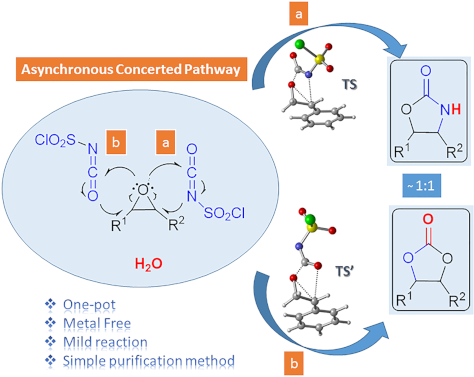
- using a safe, inexpensive, metal-free reagent, a simple purification method and shorter reaction times via a one-pot reaction. The study presents a useful method for one-pot conversion of epoxides to protected 1,2-diols and 2-amino alcohols in one reaction. In the computational part of the study, the

Graphical Abstract

Scheme 1: Oxazolidinone (1), five-membered cyclic carbonate (2) and some important compounds containing an ox...

Scheme 2: Proposed mechanisms by Keshava Murthy and Dhar [41] and De Meijere and co-workers [42].

Figure 1: Possible pathways for the formation of oxazolidinone intermediates 10 and 11. Optimized transition ...

Figure 2: Potential energy profile related to the formation of oxazolidinone intermediates 10 and 11 at the P...

Figure 3: IRC calculated for the formation of (a) 10 and (b) 11 at M06-2X/6-31+G(d,p) level. I-1, I-15, I-35, ...

Figure 4: Optimized geometries for the stationary points for the formation of 10 at PCM(DCM)/M06-2X/6-31+G(d,...

Scheme 3: Proposed mechanisms for the formation of oxazolidinone 9f.

Figure 5: Potential energy profiles for paths 1a (blue), 1b (red), 2 (green) and relative Gibbs free energies...

Figure 6: Optimized geometries for the stationary points of path 1b at PCM(DCM)/M06-2X/6-31+G(d,p)//M06-2X/6-...

Scheme 4: Proposed mechanism for the formation of five-membered cyclic carbonate 8f.

Figure 7: Potential energy profile and relative Gibbs free energies (kcal/mol) in DCM related to the formatio...

Figure 8: Optimized geometries for the stationary points of step 1 for the formation of 16 at PCM(DCM)/M06-2X...

Figure 9: Optimized geometries for the stationary points of step 2 for the formation of 17 at PCM(DCM)/M06-2X...

Figure 10: Optimized geometries for the stationary points of step 3 for the formation of PC8 at PCM(DCM)/M06-2...
Mechanochemical green synthesis of hyper-crosslinked cyclodextrin polymers
- Alberto Rubin Pedrazzo,
- Fabrizio Caldera,
- Marco Zanetti,
- Silvia Lucia Appleton,
- Nilesh Kumar Dhakar and
- Francesco Trotta
Beilstein J. Org. Chem. 2020, 16, 1554–1563, doi:10.3762/bjoc.16.127

- . Polysaccharides and, among them, starch derivatives such as cyclodextrins (CD), have recently emerged as they are safe, of low cost and biodegradable. Cyclodextrin nanosponges (CD-NS) are crosslinked cyclodextrin polymers characterized by a nanosized three-dimensional network. The reactive hydroxy groups of CDs
- , applied to organic syntheses and polymers has gained growing interest in recent years [14][15][16][17][18]. Mechanochemical syntheses are safe and represent efficient activation methods for greener processes, avoiding the use of solvents and reducing energy consumption. Recently, many examples for

Graphical Abstract

Figure 1: FTIR analysis of βNS-CDI 1:4, before and after treatment for 4 h in H2O at 40 °C, synthesized with ...

Figure 2: Thermogravimetric analysis of β-CD-based carbonate nanosponges, obtained through solution (DMF) and...

Figure 3: Thermogravimetric analysis of α, β and γ-CD-based carbonate nanosponges, obtained through ball-mill...

Figure 4: Adsorption of organic dyes by ball-mill synthesized β-CD-based carbonate nanosponges. Conditions: a...

Figure 5: ζ-Potential of bm cyclodextrin nanosponges with relative STDev (mV).

Figure 6: Hydrolysis of the imidazoyl carbonyl group in water at 40 °C.

Figure 7: Nitrogen content in weight % in cyclodextrins NS-CDI from ball mill synthesis. a) comparison betwee...

Figure 8: Simplified schematic reaction and procedure for obtaining the dye-functionalized βNS-CDI. Surface z...
Heterogeneous photocatalysis in flow chemical reactors
- Christopher G. Thomson,
- Ai-Lan Lee and
- Filipe Vilela
Beilstein J. Org. Chem. 2020, 16, 1495–1549, doi:10.3762/bjoc.16.125

- demonstrated the safe use of gaseous CF3I as a reagent for the continuous flow PRC trifluoromethylation of 5-membered heterocycles, such as N-methylpyrrole (1, Scheme 1), with a high conversion and selectivity for the monofunctionalised product 2 [62]. The system achieved full conversion for a variety of

Graphical Abstract

Figure 1: A) Bar chart of the publications per year for the topics “Photocatalysis” (49,662 instances) and “P...

Figure 2: A) Professor Giacomo Ciamician and Dr. Paolo Silber on their roof laboratory at the University of B...

Scheme 1: PRC trifluoromethylation of N-methylpyrrole (1) using hazardous gaseous CF3I safely in a flow react...

Figure 3: A) Unit cells of the three most common crystal structures of TiO2: rutile, brookite, and anatase. R...

Figure 4: Illustration of the key semiconductor photocatalysis events: 1) A photon with a frequency exceeding...

Figure 5: Photocatalytic splitting of water by oxygen vacancies on a TiO2(110) surface. Reprinted with permis...

Figure 6: Proposed adsorption modes of A) benzene, B) chlorobenzene, C) toluene, D) phenol, E) anisole, and F...

Figure 7: Structures of the sulfonate-containing organic dyes RB5 (3) and MX-5B (4) and the adsorption isothe...

Figure 8: Idealised triclinic unit cell of a g-C3N4 type polymer, displaying possible hopping transport scena...

Figure 9: Idealised structure of a perfect g-C3N4 sheet. The central unit highlighted in red represents one t...

Figure 10: Timeline of the key processes of charge transport following the photoexcitation of g-C3N4, leading ...

Scheme 2: Photocatalytic bifunctionalisation of heteroarenes using mpg-C3N4, with the selected examples 5 and ...

Figure 11: A) Structure of four linear conjugated polymer photocatalysts for hydrogen evolution, displaying th...

Figure 12: Graphical representation of the common methods used to immobilise molecular photocatalysts (PC) ont...

Figure 13: Wireless light emitter-supported TiO2 (TiO2@WLE) HPCat spheres powered by resonant inductive coupli...

Figure 14: Graphical representation of zinc–perylene diimide (Zn-PDI) supramolecular assembly photocatalysis v...

Scheme 3: Upconversion of NIR photons to the UV frequency by NaYF4:Yb,Tm nanocrystals sequentially coated wit...

Figure 15: Types of reactors employed in heterogeneous photocatalysis in flow. A) Fixed bed reactors and the s...

Figure 16: Electrochemical potential of common semiconductor, transition metal, and organic dye-based photocat...

Scheme 4: Possible mechanisms of an immobilised molecular photoredox catalyst by oxidative or reductive quenc...

Scheme 5: Scheme of the CMB-C3N4 photocatalytic decarboxylative fluorination of aryloxyacetic acids, with the...

Scheme 6: Scheme of the g-C3N4 photocatalytic desilylative coupling reaction in flow and proposed mechanism [208].

Scheme 7: Proposed mechanism of the radical cyclisation of unsaturated alkyl 2-bromo-1,3-dicarbonyl compounds...

Scheme 8: N-alkylation of benzylamine and schematic of the TiO2-coated microfluidic device [213].

Scheme 9: Proposed mechanism of the Pt@TiO2 photocatalytic deaminitive cyclisation of ʟ-lysine (23) to ʟ-pipe...

Scheme 10: A) Proposed mechanism for the photocatalytic oxidation of phenylboronic acid (24). B) Photos and SE...

Scheme 11: Proposed mechanism for the DA-CMP3 photocatalytic aza-Henry reaction performed in a continuous flow...

Scheme 12: Proposed mechanism for the formation of the cyclic product 32 by TiO2-NC HPCats in a slurry flow re...

Scheme 13: Reaction scheme for the photocatalytic synthesis of homo and hetero disulfides in flow and scope of...

Scheme 14: Reaction scheme for the MoOx/TiO2 HPCat oxidation of cyclohexane (34) to benzene. The graph shows t...

Scheme 15: Proposed mechanism of the TiO2 HPC heteroarene C–H functionalisation via aryl radicals generated fr...

Scheme 16: Scheme of the oxidative coupling of benzylamines with the HOTT-HATN HPCat and selected examples of ...

Scheme 17: Photocatalysis oxidation of benzyl alcohol (40) to benzaldehyde (41) in a microflow reactor coated ...

Figure 17: Mechanisms of Dexter and Forster energy transfer.

Scheme 18: Continuous flow process for the isomerisation of alkenes with an ionic liquid-immobilised photocata...

Scheme 19: Singlet oxygen synthetic step in the total synthesis of canataxpropellane [265].

Scheme 20: Scheme and proposed mechanism of the singlet oxygen photosensitisation by CMP_X HPCats, with the st...

Scheme 21: Structures of CMP HPCat materials applied by Vilela and co-workers for the singlet oxygen photosens...

Scheme 22: Polyvinylchloride resin-supported TDCPP photosensitisers applied for singlet oxygen photosensitisat...

Scheme 23: Structure of the ionically immobilised TPP photosensitiser on amberlyst-15 ion exchange resins (TPP...

Scheme 24: Photosensitised singlet oxygen oxidation of citronellol (46) in scCO2, with automatic phase separat...

Scheme 25: Schematic of PS-Est-BDP-Cl2 being applied for singlet oxygen photosensitisation in flow. A) Pseudo-...

Scheme 26: Reaction scheme of the singlet oxygen oxidation of furoic acid (54) using a 3D-printed microfluidic...

Figure 18: A) Photocatalytic bactericidal mechanism by ROS oxidative cleavage of membrane lipids (R = H, amino...

Figure 19: A) Suggested mechanisms for the aqueous pollutant degradation by TiO2 in a slurry flow reactor [284-287]. B)...

Figure 20: Schematic of the flow system used for the degradation of aqueous oxytetracycline (56) solutions [215]. M...

Scheme 27: Degradation of a salicylic acid (57) solution by a coupled solar photoelectro-Fenton (SPEF) process...

Figure 21: A) Schematic flow diagram using the TiO2-coated NETmix microfluidic device for an efficient mass tr...
The McKenna reaction – avoiding side reactions in phosphonate deprotection
- Katarzyna Justyna,
- Joanna Małolepsza,
- Damian Kusy,
- Waldemar Maniukiewicz and
- Katarzyna M. Błażewska
Beilstein J. Org. Chem. 2020, 16, 1436–1446, doi:10.3762/bjoc.16.119

- demonstrated that contrary to common belief: 1) BTMS itself led to the cleavage of tert-butyl carboxyesters, and 2) amines, a commonly used standard additives in the McKenna reaction were not generally safe and may promoted side reactions in the presence of certain functional groups. Besides that, we

Graphical Abstract

Scheme 1: Schematic overview of the McKenna reaction including the decomposition of BTMS in protic solvents. ...

Figure 1: The model compounds used for this study (in red: the functionality of the molecules vulnerable to s...

Scheme 2: Formation of the side products derived from 10. Conditions: An equimolar mixture of propargylamide ...

Scheme 3: Addition of HBr to compound 11.

Scheme 4: N-Alkylation of 9.

Scheme 5: N-Alkylation of 12.

Scheme 6: Exchange of the chlorine substituent with bromine in 2-chloro-N-phenethylacetamide (13) under McKen...
Disposable cartridge concept for the on-demand synthesis of turbo Grignards, Knochel–Hauser amides, and magnesium alkoxides
- Mateo Berton,
- Kevin Sheehan,
- Andrea Adamo and
- D. Tyler McQuade
Beilstein J. Org. Chem. 2020, 16, 1343–1356, doi:10.3762/bjoc.16.115

- functions in a safe and robust manner. It also demands to be low-cost in order to have any potential for real-world applications. In other words, to achieve the set goals, innovation is needed to reduce the complexity/expense of (1) pumps; (2) reactors; (3) valves; (4) fittings, and (5) chemical containers
- chemistry technologies and cartridges containing activated metals can solve most of these issues: (1) the use of activated magnesium powder packed in a column increases the reaction rate and facilitates safe separation of the metal and reagent solution; (2) an efficient heat transfer (a large surface area

Graphical Abstract

Figure 1: Comparing on-demand coffee and turbo Grignard pod-style machines.

Figure 2: Ranking of the 20 most cited Grignard reagents (SciFinder March 26, 2019).

Figure 3: On-demand prototype. A) Inside view of the pump with a flexible bag containing a yellow liquid layi...

Figure 4: Temperature evolution measured with thermocouples along the column outer surface at three different...

Figure 5: Stratified bicomponent column (Diba Omnifit EZ Solvent Plus) composed of magnesium (chips/powder, 1...

Scheme 1: Continuous flow synthesis of TMPMgCl⋅LiCl with a stratified packed-bed column of activated magnesiu...

Scheme 2: Continuous flow synthesis of TMPMgCl⋅LiBr with a stratified packed-bed column of activated magnesiu...

Scheme 3: Continuous flow synthesis of t-AmylOMgCl⋅LiCl with a stratified packed-bed column of activated magn...

Figure 6: Steady-state concentration stability during the conversion of iPrCl in THF (56 mL, 2.2 M) into iPrM...

Scheme 4: Synthesis of iPrMgCl⋅LiCl on the ODR prototype.

Scheme 5: Synthesis of HMDSMgCl⋅LiCl on the ODR prototype.
Anthelmintic drug discovery: target identification, screening methods and the role of open science
- Frederick A. Partridge,
- Ruth Forman,
- Carole J. R. Bataille,
- Graham M. Wynne,
- Marina Nick,
- Angela J. Russell,
- Kathryn J. Else and
- David B. Sattelle
Beilstein J. Org. Chem. 2020, 16, 1203–1224, doi:10.3762/bjoc.16.105

- drugs available for human treatment were initially developed as veterinary medicines. Effective and safe anthelmintic drugs can reduce prevalence, intensity and morbidity associated with STHs. Two main strategies for delivery exist: the management of diagnosed patients and preventative chemotherapy
- species in enantiomerically pure form. A clinical trial examining the bioavailability of orally dispersible tablets of levo-praziquantel has been completed [42], and a Phase III trial evaluating safety and efficacy is underway (NCT03845140). Oral PZQ is safe and efficacious against adult worms of all
- ) achieved cure rates (CR) of between 76–95% for different Schistosoma species and 63.5% for mixed S. haematobium and S. mansoni infections and mean egg reduction rates (ERR) between 86–95% [44]. However, although PZQ is safe and efficacious against adult worms, it is only given once, and as the drug does

Graphical Abstract

Figure 1: Structures of some current front-line anthelmintics discussed in this review. *Denotes the stereoge...

Figure 2: Structures of new anthelmintics drugs developed through repurposing, and new drugs or drug candidat...

Figure 3: Compounds with anthelmintic activity identified by a combination of screening against Ancylostoma c...

Figure 4: Inhibitors of S. mansoni thioredoxin glutathione reductase with anthelmintic activity [140].

Figure 5: Active compounds from anthelmintic screens using the MMV Pathogen Box. NTS: newly transformed schis...

Figure 6: Two resolution approaches to enantiopure PZQ (R)-5 discovered through A) open science and B) contra...
A systematic review on silica-, carbon-, and magnetic materials-supported copper species as efficient heterogeneous nanocatalysts in “click” reactions
- Pezhman Shiri and
- Jasem Aboonajmi
Beilstein J. Org. Chem. 2020, 16, 551–586, doi:10.3762/bjoc.16.52

- reactions that are stereospecific, high-yielding, modular, wide in scope, executable under simple reaction conditions, conductable in safe or easily removable solvents, and that generate only nonoffensive byproducts. Of course, the classical Huisgen 1,3-dipolar cycloaddition does not fit into the above

Graphical Abstract

Scheme 1: Chemical structure of the catalysts 1a and 1b and their catalytic application in CuAAC reactions.

Scheme 2: Synthetic route to the catalyst 11 and its catalytic application in CuAAC reactions.

Scheme 3: Synthetic route of dendrons, illustrated using G2-AMP 23.

Scheme 4: The catalytic application of CuYAu–Gx-AAA–SBA-15 in a CuAAC reaction.

Scheme 5: Synthetic route to the catalyst 36.

Scheme 6: Application of the catalyst 36 in CuAAC reactions.

Scheme 7: The synthetic route to the catalyst 45 and catalytic application of 45 in “click” reactions.

Scheme 8: Synthetic route to the catalyst 48 and catalytic application of 48 in “click” reactions.

Scheme 9: Synthetic route to the catalyst 58 and catalytic application of 58 in “click” reactions.

Scheme 10: Synthetic route to the catalyst 64 and catalytic application of 64 in “click” reactions.

Scheme 11: Chemical structure of the catalyst 68 and catalytic application of 68 in “click” reactions.

Scheme 12: Chemical structure of the catalyst 69 and catalytic application of 69 in “click” reactions.

Scheme 13: Synthetic route to, and chemical structure of the catalyst 74.

Scheme 14: Application of the cayalyst 74 in “click” reactions.

Scheme 15: Synthetic route to, and chemical structure of the catalyst 78 and catalytic application of 78 in “c...

Scheme 16: Synthetic route to the catalyst 85.

Scheme 17: Application of the catalyst 85 in “click” reactions.

Scheme 18: Synthetic route to the catalyst 87 and catalytic application of 87 in “click” reactions.

Scheme 19: Chemical structure of the catalyst 88 and catalytic application of 88 in “click” reactions.

Scheme 20: Synthetic route to the catalyst 90 and catalytic application of 90 in “click” reactions.

Scheme 21: Synthetic route to the catalyst 96 and catalytic application of 96 in “click” reactions.

Scheme 22: Synthetic route to the catalyst 100 and catalytic application of 100 in “click” reactions.

Scheme 23: Synthetic route to the catalyst 102 and catalytic application of 23 in “click” reactions.

Scheme 24: Synthetic route to the catalysts 108–111.

Scheme 25: Catalytic application of 108–111 in “click” reactions.

Scheme 26: Synthetic route to the catalyst 121 and catalytic application of 121 in “click” reactions.

Scheme 27: Synthetic route to 125 and application of 125 in “click” reactions.

Scheme 28: Synthetic route to the catalyst 131 and catalytic application of 131 in “click” reactions.

Scheme 29: Synthetic route to the catalyst 136.

Scheme 30: Application of the catalyst 136 in “click” reactions.

Scheme 31: Synthetic route to the catalyst 141 and catalytic application of 141 in “click” reactions.

Scheme 32: Synthetic route to the catalyst 144 and catalytic application of 144 in “click” reactions.

Scheme 33: Synthetic route to the catalyst 149 and catalytic application of 149 in “click” reactions.

Scheme 34: Synthetic route to the catalyst 153 and catalytic application of 153 in “click” reactions.

Scheme 35: Synthetic route to the catalyst 155 and catalytic application of 155 in “click” reactions.

Scheme 36: Synthetic route to the catalyst 157 and catalytic application of 157 in “click” reactions.

Scheme 37: Synthetic route to the catalyst 162.

Scheme 38: Application of the catalyst 162 in “click” reactions.

Scheme 39: Synthetic route to the catalyst 167 and catalytic application of 167 in “click” reactions.

Scheme 40: Synthetic route to the catalyst 169 and catalytic application of 169 in “click” reactions.

Scheme 41: Synthetic route to the catalyst 172.

Scheme 42: Application of the catalyst 172 in “click” reactions.
p-Pyridinyl oxime carbamates: synthesis, DNA binding, DNA photocleaving activity and theoretical photodegradation studies
- Panagiotis S. Gritzapis,
- Panayiotis C. Varras,
- Nikolaos-Panagiotis Andreou,
- Katerina R. Katsani,
- Konstantinos Dafnopoulos,
- George Psomas,
- Zisis V. Peitsinis,
- Alexandros E. Koumbis and
- Konstantina C. Fylaktakidou
Beilstein J. Org. Chem. 2020, 16, 337–350, doi:10.3762/bjoc.16.33

- classic DNA intercalator EB (Kb = 1.23 × 10⁵ M−1) as previously reported [69]. The data obtained by the UV–vis spectroscopy studies most probably indicate the interaction of the compounds with CT DNA. However, the exact mode of binding is not safe to be proposed before more experimental data can be

Graphical Abstract

Figure 1: General structures of oxime derivatives with possible DNA photocleavage ability. Left: Oxime carbox...

Scheme 1: Synthesis of O-carbamoyl amidoximes (8–13), ethanone oximes (15–20) and aldoximes (22–27). Oxime 1 ...

Figure 2: UV–vis spectra of CT DNA ([DNA] = 1.1 × 10⁻⁴ M) in buffer solution in the absence or presence of in...

Figure 3: Relative viscosity (η/η0)1/3 of CT DNA (0.1 mM) in buffer solution in the presence of compounds 11 ...

Figure 4: Plot of EB-DNA relative fluorescence emission intensity at λ = 592 nm (I/I0, %) vs r (= [compound]/...

Figure 5: DNA photocleavage of amidoxime carbamates at a concentration of 500 μM and mechanistic studies of a...

Figure 6: Potential energy curve for the dissociation of 12 in the first excited triplet state, T1. For compo...

Scheme 2: Photodissociation reaction of the derivative 12 in the T1 state and the formation of ground state r...

Scheme 3: Decarboxylation reaction of the p-chlorophenylcarbamoyloxyl radical.

Figure 7: Proposed scheme showing a possible energy transfer from acetophenone sensitizer to oxime carbamate ...

Figure 8: DNA photocleavage of compounds 8–10 and 12–13 at concentration of 500 μM, at 365 nm, in the absence...

Figure 9: DNA photocleavage of compound 12 at a concentration of 500 μM, at 312 nm, in the absence and presen...
Synthesis and herbicidal activities of aryloxyacetic acid derivatives as HPPD inhibitors
- Man-Man Wang,
- Hao Huang,
- Lei Shu,
- Jian-Min Liu,
- Jian-Qiu Zhang,
- Yi-Le Yan and
- Da-Yong Zhang
Beilstein J. Org. Chem. 2020, 16, 233–247, doi:10.3762/bjoc.16.25

- , compound II4 was safe for weed control in maize fields at a rate of 150 g ai/ha, and was identified as the most potent candidate for a novel HPPD inhibitor herbicide. The compounds described herein may provide useful guidance for the design of new HPPD inhibiting herbicides and their modification
- various species and genera and providing a theoretical basis for the design of inhibitors that are highly selective and safe [2]. In plants, HPPD inhibitors competitively restrain HPPA from chelating to FeII. The production of plastoquinone is inhibited and phytoene is accumulated when the transformation
- , II4 was found to be safe for use on maize. These results suggest that compound II4 is a promising HPPD inhibiting herbicide candidate deserving of further optimization studies. Experimental The experimental details and analytical data for intermediates C to M and title compounds were given in

Graphical Abstract

Scheme 1: The commonly recognized HPPD catalytic reaction mechanism.

Figure 1: Chemical structures of the commercial HPPD inhibitors.

Figure 2: The design strategy of aryloxyacetic acid derivatives as HPPD inhibitors and simulate the binding m...

Scheme 2: Synthetic route of the title compounds I. Reagents and conditions: (a) methyl chloroacetate, K2CO3,...

Scheme 3: Synthetic route of the title compound III. Reagents and conditions: (a) methyl chloroacetate, K2CO3...

Scheme 4: Synthetic route of the title compounds II. Reagents and conditions: (a) NaOH, TBAB, H2O, 100 °C; (b...

Figure 3: Crystal structures of I18 and III4.

Figure 4: Simulated binding mode of mesotrione (A), compound I12 (B) and compound II4 (C) with AtHPPD. The ke...

Figure 5: Sum of inhibition rate of title compounds at 150 g ai/ha. (Abbreviations: AJ, Abutilon juncea; AR, ...

Figure 6: Simulated folding mode of mesotrione (yellow sticks) and compound II4 (gray sticks) with AtHPPD. Th...