Search results
Search for "metal complexes" in Full Text gives 275 result(s) in Beilstein Journal of Organic Chemistry. Showing first 200.
Catalytic trifluoromethylation of iodoarenes by use of 2-trifluoromethylated benzimidazoline as trifluoromethylating reagent
- Tatsuhiro Uchikura,
- Nanami Kamiyama,
- Taisuke Ishikawa and
- Takahiko Akiyama
Beilstein J. Org. Chem. 2020, 16, 2442–2447, doi:10.3762/bjoc.16.198

- ; catalysis; copper; fluorine chemistry; trifluoromethylation; Introduction The introduction of a trifluoromethyl group is one of the most attractive reactions in drug discovery [1][2]. In the past decade, trifluoromethylation reactions of aryl halides in the presence of transition-metal complexes were

Graphical Abstract

Figure 1: Trifluoromethylation of aryl halides.

Figure 2: Scope of aryl iodides. Yields determined by 19F NMR spectroscopy and used ligand is given in parent...

Figure 3: Scope of heteroaryl iodides. Yields determined by 19F NMR spectroscopy and used ligand is given in ...

Figure 4: Time course of the trifluoromethylation reaction.

Figure 5: Proposed mechanism of the catalytic cycle.
Recent developments in enantioselective photocatalysis
- Callum Prentice,
- James Morrisson,
- Andrew D. Smith and
- Eli Zysman-Colman
Beilstein J. Org. Chem. 2020, 16, 2363–2441, doi:10.3762/bjoc.16.197


Graphical Abstract

Scheme 1: Amine/photoredox-catalysed α-alkylation of aldehydes with alkyl bromides bearing electron-withdrawi...

Scheme 2: Amine/HAT/photoredox-catalysed α-functionalisation of aldehydes using alkenes.

Scheme 3: Amine/cobalt/photoredox-catalysed α-functionalisation of ketones and THIQs.

Scheme 4: Amine/photoredox-catalysed α-functionalisation of aldehydes or ketones with imines. (a) Using keton...

Scheme 5: Bifunctional amine/photoredox-catalysed enantioselective α-functionalisation of aldehydes.

Scheme 6: Bifunctional amine/photoredox-catalysed α-functionalisation of aldehydes using amine catalysts via ...

Scheme 7: Amine/photoredox-catalysed RCA of iminium ion intermediates. (a) Synthesis of quaternary stereocent...

Scheme 8: Bifunctional amine/photoredox-catalysed RCA of enones in a radical chain reaction initiated by an i...

Scheme 9: Bifunctional amine/photoredox-catalysed RCA reactions of iminium ions with different radical precur...

Scheme 10: Bifunctional amine/photoredox-catalysed radical cascade reactions between enones and alkenes with a...

Scheme 11: Amine/photocatalysed photocycloadditions of iminium ion intermediates. (a) External photocatalyst u...

Scheme 12: Amine/photoredox-catalysed addition of acrolein (94) to iminium ions.

Scheme 13: Dual NHC/photoredox-catalysed acylation of THIQs.

Scheme 14: NHC/photocatalysed spirocyclisation via photoisomerisation of an extended Breslow intermediate.

Scheme 15: CPA/photoredox-catalysed aza-pinacol cyclisation.

Scheme 16: CPA/photoredox-catalysed Minisci-type reaction between azaarenes and α-amino radicals.

Scheme 17: CPA/photoredox-catalysed radical additions to azaarenes. (a) α-Amino radical or ketyl radical addit...

Scheme 18: CPA/photoredox-catalysed reduction of azaarene-derived substrates. (a) Reduction of ketones. (b) Ex...

Scheme 19: CPA/photoredox-catalysed radical coupling reactions of α-amino radicals with α-carbonyl radicals. (...

Scheme 20: CPA/photoredox-catalysed Povarov reaction.

Scheme 21: CPA/photoredox-catalysed reactions with imines. (a) Decarboxylative imine generation followed by Po...

Scheme 22: Bifunctional CPA/photocatalysed [2 + 2] photocycloadditions.

Scheme 23: PTC/photocatalysed oxygenation of 1-indanone-derived β-keto esters.

Scheme 24: PTC/photoredox-catalysed perfluoroalkylation of 1-indanone-derived β-keto esters via a radical chai...

Scheme 25: Bifunctional hydrogen bonding/photocatalysed intramolecular [2 + 2] photocycloadditions of quinolon...

Scheme 26: Bifunctional hydrogen bonding/photocatalysed intramolecular RCA cyclisation of a quinolone.

Scheme 27: Bifunctional hydrogen bonding/photocatalysed intramolecular [2 + 2] photocycloadditions of quinolon...

Scheme 28: Bifunctional hydrogen bonding/photocatalysed [2 + 2] photocycloaddition reactions. (a) First use of...

Scheme 29: Bifunctional hydrogen bonding/photocatalysed deracemisation of allenes.

Scheme 30: Bifunctional hydrogen bonding/photocatalysed deracemisation reactions. (a) Deracemisation of sulfox...

Scheme 31: Bifunctional hydrogen bonding/photocatalysed intramolecular [2 + 2] photocycloaddition of coumarins....

Scheme 32: Bifunctional hydrogen bonding/photocatalysed [2 + 2] photocycloadditions of quinolones. (a) Intramo...

Scheme 33: Hydrogen bonding/photocatalysed formal arylation of benzofuranones.

Scheme 34: Hydrogen bonding/photoredox-catalysed dehalogenative protonation of α,α-chlorofluoro ketones.

Scheme 35: Hydrogen bonding/photoredox-catalysed reductions. (a) Reduction of 1,2-diketones. (b) Reduction of ...

Scheme 36: Hydrogen bonding/HAT/photocatalysed deracemisation of cyclic ureas.

Scheme 37: Hydrogen bonding/HAT/photoredox-catalysed synthesis of cyclic sulfonamides.

Scheme 38: Hydrogen bonding/photoredox-catalysed reaction between imines and indoles.

Scheme 39: Chiral cation/photoredox-catalysed radical coupling of two α-amino radicals.

Scheme 40: Chiral phosphate/photoredox-catalysed hydroetherfication of alkenols.

Scheme 41: Chiral phosphate/photoredox-catalysed synthesis of pyrroloindolines.

Scheme 42: Chiral anion/photoredox-catalysed radical cation Diels–Alder reaction.

Scheme 43: Lewis acid/photoredox-catalysed cycloadditions of carbonyls. (a) Formal [2 + 2] cycloaddition of en...

Scheme 44: Lewis acid/photoredox-catalysed RCA reaction using a scandium Lewis acid between α-amino radicals a...

Scheme 45: Lewis acid/photoredox-catalysed RCA reaction using a copper Lewis acid between α-amino radicals and...

Scheme 46: Lewis acid/photoredox-catalysed synthesis of 1,2-amino alcohols from aldehydes and nitrones using a...

Scheme 47: Lewis acid/photocatalysed [2 + 2] photocycloadditions of enones and alkenes.

Scheme 48: Meggers’s chiral-at-metal catalysts.

Scheme 49: Lewis acid/photoredox-catalysed α-functionalisation of ketones with alkyl bromides bearing electron...

Scheme 50: Bifunctional Lewis acid/photoredox-catalysed radical coupling reaction using α-chloroketones and α-...

Scheme 51: Lewis acid/photocatalysed RCA of enones. (a) Using aldehydes as acyl radical precursors. (b) Other ...

Scheme 52: Bifunctional Lewis acid/photocatalysis for a photocycloaddition of enones.

Scheme 53: Lewis acid/photoredox-catalysed RCA reactions of enones using DHPs as radical precursors.

Scheme 54: Lewis acid/photoredox-catalysed functionalisation of β-ketoesters. (a) Hydroxylation reaction catal...

Scheme 55: Bifunctional copper-photocatalysed alkylation of imines.

Scheme 56: Copper/photocatalysed alkylation of imines. (a) Bifunctional copper catalysis using α-silyl amines....

Scheme 57: Bifunctional Lewis acid/photocatalysed intramolecular [2 + 2] photocycloaddition.

Scheme 58: Bifunctional Lewis acid/photocatalysed [2 + 2] photocycloadditions (a) Intramolecular cycloaddition...

Scheme 59: Bifunctional Lewis acid/photocatalysed rearrangement of 2,4-dieneones.

Scheme 60: Lewis acid/photocatalysed [2 + 2] cycloadditions of cinnamate esters and styrenes.

Scheme 61: Nickel/photoredox-catalysed arylation of α-amino acids using aryl bromides.

Scheme 62: Nickel/photoredox catalysis. (a) Desymmetrisation of cyclic meso-anhydrides using benzyl trifluorob...

Scheme 63: Nickel/photoredox catalysis for the acyl-carbamoylation of alkenes with aldehydes using TBADT as a ...

Scheme 64: Bifunctional copper/photoredox-catalysed C–N coupling between α-chloro amides and carbazoles or ind...

Scheme 65: Bifunctional copper/photoredox-catalysed difunctionalisation of alkenes with alkynes and alkyl or a...

Scheme 66: Copper/photoredox-catalysed decarboxylative cyanation of benzyl phthalimide esters.

Scheme 67: Copper/photoredox-catalysed cyanation reactions using TMSCN. (a) Propargylic cyanation (b) Ring ope...

Scheme 68: Palladium/photoredox-catalysed allylic alkylation reactions. (a) Using alkyl DHPs as radical precur...

Scheme 69: Manganese/photoredox-catalysed epoxidation of terminal alkenes.

Scheme 70: Chromium/photoredox-catalysed allylation of aldehydes.

Scheme 71: Enzyme/photoredox-catalysed dehalogenation of halolactones.

Scheme 72: Enzyme/photoredox-catalysed dehalogenative cyclisation.

Scheme 73: Enzyme/photoredox-catalysed reduction of cyclic imines.

Scheme 74: Enzyme/photocatalysed enantioselective reduction of electron-deficient alkenes as mixtures of (E)/(Z...

Scheme 75: Enzyme/photoredox catalysis. (a) Deacetoxylation of cyclic ketones. (b) Reduction of heteroaromatic...

Scheme 76: Enzyme/photoredox-catalysed synthesis of indole-3-ones from 2-arylindoles.

Scheme 77: Enzyme/HAT/photoredox catalysis for the DKR of primary amines.

Scheme 78: Bifunctional enzyme/photoredox-catalysed benzylic C–H hydroxylation of trifluoromethylated arenes.
Synthetic approaches to bowl-shaped π-conjugated sumanene and its congeners
- Shakeel Alvi and
- Rashid Ali
Beilstein J. Org. Chem. 2020, 16, 2212–2259, doi:10.3762/bjoc.16.186

- , since its first successful synthesis, a variety of functionalized sumanenes as well as heterosumanenes have been developed because of their unique physiochemical properties. For example, bowl-to-bowl inversion, bowl depth, facial selectivity, crystal packing, metal complexes, intermolecular charge
- palladium(II) was carried out in the presence of PdCl2(MeCN)2 in a stepwise manner, confirmed by UV–vis spectroscopic technique. The cyclopentadienyl (Cp) ligand has its own identity in the field of organometallic chemistry as a plethora of transition metal complexes contain this moiety in their structures
- . In contrast, not much is reported related to the η5-coordinated alkali metal complexes though the first report came around 120 years ago. To this context, in 2015, Hirao and Petrukhina’s group have reported the first alkali metal–sumanene complex K7(C21H102−)2(C21H93−)·8THF (137) having di- and

Graphical Abstract

Figure 1: Representation of corannulene (1) and sumanene (2), the subunits of fullerene (C60).

Scheme 1: Mehta’s unsuccessful effort for the synthesis of sumanene scaffold 2.

Scheme 2: First synthesis of sumanene 2 by Sakurai et al. from norbornadiene 10.

Scheme 3: Synthesis of trimethylsumanene 28 from easily accessible norbornadiene (10).

Scheme 4: Generation of anions 29–31 and the preparation of tris(trimethylsilyl)sumanene 32.

Scheme 5: Synthesis of tri- and hexa-substituted sumanene derivatives.

Scheme 6: Synthesis of bowl-shaped π-extended sumanene derivatives 37a–f.

Scheme 7: Synthesis of monooxasumanene 38, trioxosumanene 40 along with imination of them.

Scheme 8: Synthesis of trimethylsumanenetrione 46 and exo-functionalized products 45a,b.

Scheme 9: Synthesis of bisumanenylidene 47 and sumanene dimer 48 from 2.

Scheme 10: The mono-substitution of 2 to generate diverse mono-sumanene derivatives 49a–d.

Scheme 11: Synthesis of sumanene building block 53 useful for further extension.

Scheme 12: Synthesis of hexafluorosumanene derivative 55 by Sakurai and co-workers.

Scheme 13: Preparation of sumanene-based carbene 60 and its reaction with cyclohexane.

Scheme 14: Barton–Kellogg reaction for the synthesis of sterically hindered alkenes.

Scheme 15: Synthesis of hydroxysumanene 68 by employing Baeyer–Villiger oxidation.

Scheme 16: Synthesis of sumanene derivatives having functionality at an internal carbon.

Scheme 17: Mechanism for nucleophilic substitution reaction at the internal carbon.

Scheme 18: Synthesis of diverse monosubstituted sumanene derivatives.

Scheme 19: Synthesis of di- and trisubstituted sumanene derivatives from sumanene (2).

Scheme 20: Preparation of monochlorosumanene 88 and hydrogenation of sumanene (2).

Scheme 21: The dimer 90 and bissumanenyl 92 achieved from halosumannes.

Scheme 22: Pyrenylsumanene 93 involving the Suzuki-coupling as a key transformation.

Scheme 23: Synthesis of various hexaarylsumanene derivatives using the Suzuki-coupling reaction.

Scheme 24: Synthesis of hexasubstituted sumanene derivatives 96 and 97.

Scheme 25: Synthesis of thioalkylsumanenes via an aromatic nucleophilic substitution reaction.

Scheme 26: Synthesis of tris(ethoxycarbonylethenyl)sumanene derivative 108.

Scheme 27: Synthesis of ferrocenyl-based sumanene derivatives.

Scheme 28: Synthesis of sumanenylferrocene architectures 118 and 119 via Negishi coupling.

Scheme 29: Diosmylation and the synthesis of phenylboronate ester 121 of sumanene.

Scheme 30: Synthesis of the iron-complex of sumanene.

Scheme 31: Synthesis of tri- and mononuclear sumanenyl zirconocene complexes.

Scheme 32: Synthesis of [CpRu(η6-sumanene)]PF6.

Scheme 33: Preparation of sumanene-based porous coordination networks 127 (spherical tetramer units) and 128 (...

Scheme 34: Synthesis of sumanenylhafnocene complexes 129 and 130.

Scheme 35: Synthesis of 134 and 135 along with PdII coordination complex 136.

Scheme 36: Synthesis of alkali metals sumanene complex K7(C21H102−)2(C21H93−)·8THF (137) containing di- and tr...

Scheme 37: The encapsulation of a Cs+ ion between two sumanenyl anions.

Scheme 38: Synthesis of monothiasumanene 140 and dithiasumanene 141 from 139.

Scheme 39: Synthesis of trithiasumanene 151 by Otsubo and his co-workers.

Scheme 40: Synthesis of trithiasumanene derivatives 155 and 156.

Scheme 41: Synthetic route towards hexathiolated trithiasumanenes 158.

Scheme 42: Synthesis of triselenasumanene 160 by Shao and teammates.

Scheme 43: Synthesis of tritellurasumanene derivatives from triphenylene skeletons.

Scheme 44: Synthesis of pyrazine-fused sumanene architectures through condensation reaction.

Scheme 45: Treatment of the trichalcogenasumanenes with diverse oxidative reagents.

Scheme 46: Ring-opening reaction with H2O2 and oxone of heterasumanenes 178 and 179.

Scheme 47: Synthesis of polycyclic compounds from sumanene derivatives.

Scheme 48: Synthesis of diimide-based heterocycles reported by Shao’s and co-workers.

Scheme 49: Synthesis of pristine trichalcogenasumanenes, 151, 205, and 206.

Scheme 50: Synthesis of trichalcogenasumanenes via hexaiodotriphenylene precursor 208.

Scheme 51: Synthesis of trisilasumanenes 214 and 215.

Scheme 52: Synthesis of trisilasumanene derivatives 218 and 219.

Scheme 53: Synthesis of novel trigermasumanene derivative 223.

Scheme 54: An attempt towards the synthesis of tristannasumanene derivative 228.

Scheme 55: Synthesis of triphosphasumanene trisulfide 232 from commercially available 229.

Scheme 56: The doping of sumanene derivatives with chalcogens (S, Se, Te) and phosphorus.

Scheme 57: Synthesis of heterasumanene containing three different heteroatoms.

Scheme 58: Synthesis of trichalcogenasumanene derivatives 240 and 179.

Scheme 59: Preparation of trichalcogenasumanenes 245 and 248.

Scheme 60: Design and synthesis of trichalcogenasumanene derivatives 252 and 178.

Scheme 61: Synthesis of spirosumanenes 264–269 and non-spiroheterasumanenes 258–263.

Scheme 62: Synthesis of sumanene-type hetero polycyclic compounds.

Scheme 63: Synthesis of triazasumanenes 288 and its sulfone congener 287.

Scheme 64: Synthesis of C3-symmetric chiral triaryltriazasumanenes via cross-coupling reaction.

Scheme 65: Synthesis of mononaphthosumanene 293 using Suzuki coupling as a key step.

Scheme 66: Synthesis of di- and trinaphthosumanene derivatives 302–304.

Scheme 67: Synthesis of hemifullerene skeletons by Hirao’s group.

Scheme 68: Design and construction of C70 fragment from a C60 sumanene fragment.
Photosensitized direct C–H fluorination and trifluoromethylation in organic synthesis
- Shahboz Yakubov and
- Joshua P. Barham
Beilstein J. Org. Chem. 2020, 16, 2151–2192, doi:10.3762/bjoc.16.183

- , triplet state energies and lifetimes of several small organic molecule/dye PSCats. Figure 7 shows the corresponding information for selected prototypical transition metal complexes. 2.2 Fluorination reagents An extensive discussion on the different types of fluorination reagents is beyond the scope of

Graphical Abstract

Figure 1: Fluorine-containing drugs.

Figure 2: Fluorinated agrochemicals.

Scheme 1: Selectivity of fluorination reactions.

Scheme 2: Different mechanisms of photocatalytic activation. Sub = substrate.

Figure 3: Jablonski diagram showing visible-light-induced energy transfer pathways: a) absorption, b) IC, c) ...

Figure 4: Schematic illustration of TTET.

Figure 5: Organic triplet PSCats.

Figure 6: Additional organic triplet PSCats.

Figure 7: A) Further organic triplet PSCats and B) transition metal triplet PSCats.

Figure 8: Different fluorination reagents grouped by generation.

Scheme 3: Synthesis of Selectfluor®.

Scheme 4: General mechanism of PS TTET C(sp3)–H fluorination.

Scheme 5: Selective benzylic mono- and difluorination using 9-fluorenone and xanthone PSCats, respectively.

Scheme 6: Chen’s photosensitized monofluorination: reaction scope.

Scheme 7: Chen’s photosensitized benzylic difluorination reaction scope.

Scheme 8: Photosensitized monofluorination of ethylbenzene on a gram scale.

Scheme 9: Substrate scope of Tan’s AQN-photosensitized C(sp3)–H fluorination.

Scheme 10: AQN-photosensitized C–H fluorination reaction on a gram scale.

Scheme 11: Reaction mechanism of the AQN-assisted fluorination.

Figure 9: 3D structures of the singlet ground and triplet excited states of Selectfluor®.

Scheme 12: Associated transitions for the activation of acetophenone by violet light.

Scheme 13: Ethylbenzene C–H fluorination with various PSCats and conditions.

Scheme 14: Effect of different PSCats on the C(sp3)–H fluorination of cyclohexane (39).

Scheme 15: Reaction scope of Chen’s acetophenone-photosensitized C(sp3)–H fluorination reaction.

Figure 10: a) Site-selectivity of Chen’s acetophenone-photosensitized C–H fluorination reaction [201]. b) Site-sele...

Scheme 16: Formation of the AQN–Selectfluor® exciplex Int1.

Scheme 17: Generation of the C3 2° pentane radical and the Selectfluor® N-radical cation from the exciplex.

Scheme 18: Hydrogen atom abstraction by the Selectfluor® N-radical cation from pentane to give the C3 2° penta...

Scheme 19: Fluorine atom transfer from Selectfluor® to the C3 2° pentane radical to yield 3-fluoropentane and ...

Scheme 20: Barrierless fluorine atom transfer from Int1 to the C3 2° pentane radical to yield 3-fluoropentane,...

Scheme 21: Ketone-directed C(sp3)–H fluorination.

Scheme 22: Ketone-directed fluorination through a 5- and a 6-membered transition state, respectively.

Scheme 23: Effect of different PSCats on the photosensitized C(sp3)–H fluorination of 47.

Scheme 24: Substrate scope of benzil-photoassisted C(sp3)–H fluorinations.

Scheme 25: A) Benzil-photoassisted enone-directed C(sp3)–H fluorination. B) Classification of the reaction mod...

Scheme 26: A) Xanthone-photoassisted ketal-directed C(sp3)–H fluorination. B) Substrate scope. C) C–H fluorina...

Scheme 27: Rationale for the selective HAT at the C2 C–H bond of galactose acetonide.

Scheme 28: Photosensitized C(sp3)–H benzylic fluorination of a peptide using different PSCats.

Scheme 29: Peptide scope of 5-benzosuberenone-photoassisted C(sp3)–H fluorinations.

Scheme 30: Continuous flow PS TTET monofluorination of 72.

Scheme 31: Photosensitized C–H fluorination of N-butylphthalimide as a PSX.

Scheme 32: Substrate scope and limitations of the PSX C(sp3)–H monofluorination.

Scheme 33: Substrate crossover monofluorination experiment.

Scheme 34: PS TTET mechanism proposed by Hamashima and co-workers.

Scheme 35: Photosensitized TFM of 78 to afford α-trifluoromethylated ketone 80.

Scheme 36: Substrate scope for photosensitized styrene TFM to give α-trifluoromethylated ketones.

Scheme 37: Control reactions for photosensitized TFM of styrenes.

Scheme 38: Reaction mechanism for photosensitized TFM of styrenes to afford α-trifluoromethylated ketones.

Scheme 39: Reaction conditions for TFMs to yield the cis- and the trans-product, respectively.

Scheme 40: Substrate scope of trifluoromethylated (E)-styrenes.

Scheme 41: Strategies toward trifluoromethylated (Z)-styrenes.

Scheme 42: Substrate scope of trifluoromethylated (Z)-styrenes.

Scheme 43: Reaction mechanism for photosensitized TFM of styrenes to afford E- or Z-products.
Convenient access to pyrrolidin-3-ylphosphonic acids and tetrahydro-2H-pyran-3-ylphosphonates with multiple contiguous stereocenters from nonracemic adducts of a Ni(II)-catalyzed Michael reaction
- Alexander N. Reznikov,
- Dmitry S. Nikerov,
- Anastasiya E. Sibiryakova,
- Victor B. Rybakov,
- Evgeniy V. Golovin and
- Yuri N. Klimochkin
Beilstein J. Org. Chem. 2020, 16, 2073–2079, doi:10.3762/bjoc.16.174

- metal-complexes-catalyzed [23][24][25][26] or organocatalyzed [27][28][29][30][31][32] Michael reaction is one of the most important synthetic tools for the asymmetric formation of a C–C bond. Moreover, the generation of the first stereocenter of a given configuration during the catalytic process leads

Graphical Abstract

Figure 1: Pharmacologically active nonracemic phosphonates with heterocyclic moieties.

Figure 2: Starting nonracemic 4-nitro-2-oxophosphonates.

Scheme 1: Intermolecular N-methylation of reduction product 7.

Scheme 2: Synthesis of pyrrolidinyl phosphonic acids 11a–d.

Figure 3: ORTEP diagram of (2R,3R,4S)-10a.

Scheme 3: Synthesis of tetrahydropyranylphosphonates 13a–f via diastereoselective Henry/acetalyzation reactio...

Figure 4: ORTEP diagram of (2S,3R,4S,5S,6R)-13b.

Scheme 4: Synthesis of (3,4-dihydro-2H-pyran-5-yl)phosphonate 14.
Synergy between supported ionic liquid-like phases and immobilized palladium N-heterocyclic carbene–phosphine complexes for the Negishi reaction under flow conditions
- Edgar Peris,
- Raúl Porcar,
- María Macia,
- Jesús Alcázar,
- Eduardo García-Verdugo and
- Santiago V. Luis
Beilstein J. Org. Chem. 2020, 16, 1924–1935, doi:10.3762/bjoc.16.159
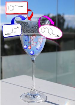
- pursuit of NHC immobilized metal complexes many different materials of organic and inorganic nature have been used as supports [5]. Several reports describe the synthesis of supported palladium–NHC complexes (Pd–NHC) and their application in cross-coupling reactions [8][9][10]. The main flaw of this type

Graphical Abstract

Scheme 1: Synthesis of NHC-supported catalysts.

Scheme 2: Negishi benchmark reaction.

Figure 1: Negishi reaction catalyzed by immobilized NHC–Pd complexes. Conditions: methyl 4-bromobenzoate (0.2...

Scheme 3: Synthesis of immobilized NHC–Pd–RuPhos.

Figure 2: Negishi model reaction between 5 and 6 under flow conditions catalyzed by 4b. V = 0.535 mL, 363 mg ...

Figure 3: Negishi model reaction under flow conditions catalyzed by 8a. V = 2.9 mL, 1.25 g of catalyst, resid...

Figure 4: Negishi reaction between 5 and 6 catalyzed by 8a in the presence of SILLPs. a) Yield (%) vs time fo...

Figure 5: TEM images of the polymers after the Negishi reaction between 5 and 6. a) 8a, bar scale 20 nm, PdNP...

Scheme 4: Pd species immobilized onto SILLPs. i) 1 g SILLP 10, 100 mg PdCl2 in milli-Q® water (100 mL 1% HCl,...

Figure 6: Negishi reaction between 5 and 6 catalyzed by 11. 1 equiv methyl 4-bromobenzoate (6, 0.25 mmol), 2 ...

Figure 7: Negishi reaction between 5 and 6 under flow conditions catalyzed by 8a in the presence of a scaveng...

Figure 8: Effect of the structure of the SILLP scavenger for the Negishi reaction between 5 and 6 under flow ...

Figure 9: TEM images of the polymer after the Negishi reaction between 5 and 6 under flow conditions. a) 8a + ...
One-pot synthesis of oxazolidinones and five-membered cyclic carbonates from epoxides and chlorosulfonyl isocyanate: theoretical evidence for an asynchronous concerted pathway
- Esra Demir,
- Ozlem Sari,
- Yasin Çetinkaya,
- Ufuk Atmaca,
- Safiye Sağ Erdem and
- Murat Çelik
Beilstein J. Org. Chem. 2020, 16, 1805–1819, doi:10.3762/bjoc.16.148
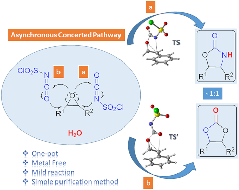
- reaction with the metal complexes or catalysts, and the reaction of a diol with toxic phosgene are the most common processes [16][17][33][34][35][36]. CSI, a highly reactive and versatile isocyanate, reacts with epoxides to give five-membered cyclic carbonates and oxazolidinones [37][38][39]. In 1984

Graphical Abstract

Scheme 1: Oxazolidinone (1), five-membered cyclic carbonate (2) and some important compounds containing an ox...

Scheme 2: Proposed mechanisms by Keshava Murthy and Dhar [41] and De Meijere and co-workers [42].

Figure 1: Possible pathways for the formation of oxazolidinone intermediates 10 and 11. Optimized transition ...

Figure 2: Potential energy profile related to the formation of oxazolidinone intermediates 10 and 11 at the P...

Figure 3: IRC calculated for the formation of (a) 10 and (b) 11 at M06-2X/6-31+G(d,p) level. I-1, I-15, I-35, ...

Figure 4: Optimized geometries for the stationary points for the formation of 10 at PCM(DCM)/M06-2X/6-31+G(d,...

Scheme 3: Proposed mechanisms for the formation of oxazolidinone 9f.

Figure 5: Potential energy profiles for paths 1a (blue), 1b (red), 2 (green) and relative Gibbs free energies...

Figure 6: Optimized geometries for the stationary points of path 1b at PCM(DCM)/M06-2X/6-31+G(d,p)//M06-2X/6-...

Scheme 4: Proposed mechanism for the formation of five-membered cyclic carbonate 8f.

Figure 7: Potential energy profile and relative Gibbs free energies (kcal/mol) in DCM related to the formatio...

Figure 8: Optimized geometries for the stationary points of step 1 for the formation of 16 at PCM(DCM)/M06-2X...

Figure 9: Optimized geometries for the stationary points of step 2 for the formation of 17 at PCM(DCM)/M06-2X...

Figure 10: Optimized geometries for the stationary points of step 3 for the formation of PC8 at PCM(DCM)/M06-2...
When metal-catalyzed C–H functionalization meets visible-light photocatalysis
- Lucas Guillemard and
- Joanna Wencel-Delord
Beilstein J. Org. Chem. 2020, 16, 1754–1804, doi:10.3762/bjoc.16.147

- activation, a catalytic amount of a transition metal (generally Pd, Rh and Ru) is frequently used in combination with a stoichiometric amount of an external oxidant (typically Cu or Ag salts). Such additional oxidants are required if transiently produced low-valent metal complexes need to be reoxidized by

Graphical Abstract

Figure 1: Concept of dual synergistic catalysis.

Figure 2: Classification of catalytic systems involving two catalysts.

Figure 3: General mechanism for the dual nickel/photoredox catalytic system.

Figure 4: General mechanisms for C–H activation catalysis involving different reoxidation strategies.

Figure 5: Indole synthesis via dual C–H activation/photoredox catalysis.

Figure 6: Proposed mechanism for the indole synthesis via dual catalysis.

Figure 7: Oxidative Heck reaction on arenes via the dual catalysis.

Figure 8: Proposed mechanism for the Heck reaction on arenes via dual catalysis.

Figure 9: Oxidative Heck reaction on phenols via the dual catalysis.

Figure 10: Proposed mechanism for the Heck reaction on phenols via dual catalysis.

Figure 11: Carbazole synthesis via dual C–H activation/photoredox catalysis.

Figure 12: Proposed mechanism for the carbazole synthesis via dual catalysis.

Figure 13: Carbonylation of enamides via the dual C–H activation/photoredox catalysis.

Figure 14: Proposed mechanism for carbonylation of enamides via dual catalysis.

Figure 15: Annulation of benzamides via the dual C–H activation/photoredox catalysis.

Figure 16: Proposed mechanism for the annulation of benzamides via dual catalysis.

Figure 17: Synthesis of indoles via the dual C–H activation/photoredox catalysis.

Figure 18: Proposed mechanism for the indole synthesis via dual catalysis.

Figure 19: General concept of dual catalysis merging C–H activation and photoredox catalysis.

Figure 20: The first example of dual catalysis merging C–H activation and photoredox catalysis.

Figure 21: Proposed mechanism for the C–H arylation with diazonium salts via dual catalysis.

Figure 22: Dual catalysis merging C–H activation/photoredox using diaryliodonium salts.

Figure 23: Direct arylation via the dual catalytic system reported by Xu.

Figure 24: Direct arylation via dual catalytic system reported by Balaraman.

Figure 25: Direct arylation via dual catalytic system reported by Guo.

Figure 26: C(sp3)–H bond arylation via the dual Pd/photoredox catalytic system.

Figure 27: Acetanilide derivatives acylation via the dual C–H activation/photoredox catalysis.

Figure 28: Proposed mechanism for the C–H acylation with α-ketoacids via dual catalysis.

Figure 29: Acylation of azobenzenes via the dual catalysis C–H activation/photoredox.

Figure 30: C2-acylation of indoles via the dual C–H activation/photoredox catalysis.

Figure 31: Proposed mechanism for the C2-acylation of indoles with aldehydes via dual catalysis.

Figure 32: C2-acylation of indoles via the dual C–H activation/photoredox catalysis.

Figure 33: Perfluoroalkylation of arenes via the dual C–H activation/photoredox catalysis.

Figure 34: Proposed mechanism for perfluoroalkylation of arenes via dual catalysis.

Figure 35: Sulfonylation of 1-naphthylamides via the dual C–H activation/photoredox catalysis.

Figure 36: Proposed mechanism for sulfonylation of 1-naphthylamides via dual catalysis.

Figure 37: meta-C–H Alkylation of arenes via visible-light metallaphotocatalysis.

Figure 38: Alternative procedure for meta-C–H alkylation of arenes via metallaphotocatalysis.

Figure 39: Proposed mechanism for meta-C–H alkylation of arenes via metallaphotocatalysis.

Figure 40: C–H borylation of arenes via visible-light metallaphotocatalysis.

Figure 41: Proposed mechanism for C–H borylation of arenes via visible-light metallaphotocatalysis.

Figure 42: Undirected C–H aryl–aryl cross coupling via dual gold/photoredox catalysis.

Figure 43: Proposed mechanism for the undirected C–H aryl–aryl cross-coupling via dual catalysis.

Figure 44: Undirected C–H arylation of (hetero)arenes via dual manganese/photoredox catalysis.

Figure 45: Proposed mechanism for the undirected arylation of (hetero)arenes via dual catalysis.

Figure 46: Photoinduced C–H arylation of azoles via copper catalysis.

Figure 47: Photo-induced C–H chalcogenation of azoles via copper catalysis.

Figure 48: Decarboxylative C–H adamantylation of azoles via dual cobalt/photoredox catalysis.

Figure 49: Proposed mechanism for the C–H adamantylation of azoles via dual catalysis.

Figure 50: General mechanisms for the “classical” (left) and Cu-free variant (right) Sonogoshira reaction.

Figure 51: First example of a dual palladium/photoredox catalysis for Sonogashira-type couplings.

Figure 52: Arylation of terminal alkynes with diazonium salts via dual gold/photoredox catalysis.

Figure 53: Proposed mechanism for the arylation of terminal alkynes via dual catalysis.

Figure 54: C–H Alkylation of alcohols promoted by H-atom transfer (HAT).

Figure 55: Proposed mechanism for the C–H alkylation of alcohols promoted by HAT.

Figure 56: C(sp3)–H arylation of latent nucleophiles promoted by H-atom transfer.

Figure 57: Proposed mechanism for the C(sp3)–H arylation of latent nucleophiles promoted by HAT.

Figure 58: Direct α-arylation of alcohols promoted by H-atom transfer.

Figure 59: Proposed mechanism for the direct α-arylation of alcohols promoted by HAT.

Figure 60: C–H arylation of amines via dual Ni/photoredox catalysis.

Figure 61: Proposed mechanism for the C–H arylation of amines via dual Ni/photoredox catalysis.

Figure 62: C–H functionalization of nucleophiles via excited ketone/nickel dual catalysis.

Figure 63: Proposed mechanism for the C–H functionalization enabled by excited ketones.

Figure 64: Selective sp3–sp3 cross-coupling promoted by H-atom transfer.

Figure 65: Proposed mechanism for the selective sp3–sp3 cross-coupling promoted by HAT.

Figure 66: Direct C(sp3)–H acylation of amines via dual Ni/photoredox catalysis.

Figure 67: Proposed mechanism for the C–H acylation of amines via dual Ni/photoredox catalysis.

Figure 68: C–H hydroalkylation of internal alkynes via dual Ni/photoredox catalysis.

Figure 69: Proposed mechanism for the C–H hydroalkylation of internal alkynes.

Figure 70: Alternative procedure for the C–H hydroalkylation of ynones, ynoates, and ynamides.

Figure 71: Allylic C(sp3)–H activation via dual Ni/photoredox catalysis.

Figure 72: Proposed mechanism for the allylic C(sp3)–H activation via dual Ni/photoredox catalysis.

Figure 73: Asymmetric allylation of aldehydes via dual Cr/photoredox catalysis.

Figure 74: Proposed mechanism for the asymmetric allylation of aldehydes via dual catalysis.

Figure 75: Aldehyde C–H functionalization promoted by H-atom transfer.

Figure 76: Proposed mechanism for the C–H functionalization of aldehydes promoted by HAT.

Figure 77: Direct C–H arylation of strong aliphatic bonds promoted by HAT.

Figure 78: Proposed mechanism for the C–H arylation of strong aliphatic bonds promoted by HAT.

Figure 79: Direct C–H trifluoromethylation of strong aliphatic bonds promoted by HAT.

Figure 80: Proposed mechanism for the C–H trifluoromethylation of strong aliphatic bonds.
Clickable azide-functionalized bromoarylaldehydes – synthesis and photophysical characterization
- Dominik Göbel,
- Marius Friedrich,
- Enno Lork and
- Boris J. Nachtsheim
Beilstein J. Org. Chem. 2020, 16, 1683–1692, doi:10.3762/bjoc.16.139

- inert conditions [28] are necessary to facilitate an afterglow emission. Most phosphorescence studies are focused on metal complexes due to a strong heavy atom-induced spin-orbit coupling [29][30][31][32][33]. Considering the high price and the toxicity of many metal complexes, pure organic phosphors

Graphical Abstract

Scheme 1: a) Schematic depiction of the Jablonski diagram. b) Schematic representation of El-Sayed’s rule.

Figure 1: Top: literature examples of organic compounds showing RTP in the crystalline state (a) and in solut...

Scheme 2: Reaction conditions for para-bromobenzaldehyde 3: a) 1) 2-amino-2-methylpropan-1-ol, 4 Å MS, CH2Cl2...

Scheme 3: Reaction conditions: a) Br2, Fe powder, CHCl3, 0 °C, 4 h, 99%; b) KOH, KI, MeI, DMSO, 25 °C, 18 h, ...

Scheme 4: Reaction conditions: a) 1) NaH, THF, 0 °C, 30 min; 2) MeI, THF, 0 °C to 25 °C, 2 h, 99%; b) 1) MeOT...

Scheme 5: a) CuAAC reactions of azide-functionalized bromocarbaldehydes 3, 4 and 5 with terminal alkynes to t...

Figure 2: a) Normalized UV–vis absorption spectra of 3 (blue line), 34 (olive line), 4 (green line) and 38 (r...

Figure 3: a) Normalized UV–vis absorption spectra of 5 (blue line), 16 (green line), 42 (olive line) and 45 (...
Pauson–Khand reaction of fluorinated compounds
- Jorge Escorihuela,
- Daniel M. Sedgwick,
- Alberto Llobat,
- Mercedes Medio-Simón,
- Pablo Barrio and
- Santos Fustero
Beilstein J. Org. Chem. 2020, 16, 1662–1682, doi:10.3762/bjoc.16.138

- described protocols for the fluorinated PKR are based on the cobalt-catalyzed version, and only a few examples have used other transition metal complexes. In this regard, significant advances can come from the careful selection of the metal complex and the CO source. The encouraging results described in

Graphical Abstract

Scheme 1: Schematic representation of the Pauson–Khand reaction.

Scheme 2: Substrates included in this review.

Scheme 3: Commonly accepted mechanism for the Pauson–Khand reaction.

Scheme 4: Regioselectivity of the PKR.

Scheme 5: Variability at the acetylenic and olefinic counterpart.

Scheme 6: Pauson–Khand reaction of fluoroolefinic enynes reported by the group of Ishizaki [46].

Scheme 7: PKR of enynes bearing fluorinated groups on the alkynyl moiety, reported by the group of Ishizaki [46]....

Scheme 8: Intramolecular PKR of 1,7-enynes reported by the group of Billard [47].

Scheme 9: Intramolecular PKR of 1,7-enynes reported by the group of Billard [48].

Scheme 10: Intramolecular PKR of 1,7-enynes by the group of Bonnet-Delpon [49]. Reaction conditions: i) Co(CO)8 (1...

Scheme 11: Intramolecular PKR of 1,6-enynes reported by the group of Ichikawa [50].

Scheme 12: Intramolecular Rh(I)-catalyzed PKR reported by the group of Hammond [52].

Scheme 13: Intramolecular PKR of allenynes reported by the group of Osipov [53].

Scheme 14: Intramolecular PKR of 1,7-enynes reported by the group of Osipov [53].

Scheme 15: Intramolecular PKR of fluorine-containing 1,6-enynes reported by the Konno group [54].

Scheme 16: Diastereoselective PKR with enantioenriched fluorinated enynes 34 [55].

Scheme 17: Intramolecular PKR reported by the group of Martinez-Solorio [56].

Scheme 18: Fluorine substitution at the olefinic counterpart.

Scheme 19: Synthesis of fluorinated enynes 37 [59].

Scheme 20: Fluorine-containing substrates in PKR [59].

Scheme 21: Pauson Khand reaction for fluorinated enynes by the Fustero group: scope and limitations [59].

Scheme 22: Synthesis of chloro and bromo analogues [59].

Scheme 23: Dimerization pathway [59].

Scheme 24: Synthesis of fluorine-containing N-tethered 1,7-enynes [61].

Scheme 25: Intramolecular PKR of chiral N-tethered fluorinated 1,7-enynes [61].

Scheme 26: Examples of further modifications to the Pauson−Khand adducts [61].

Scheme 27: Asymmetric synthesis the fluorinated enynes 53.

Scheme 28: Intramolecular PKR of chiral N-tethered 1,7-enynes 53 [64].

Scheme 29: Intramolecular PKR of chiral N-tethered 1,7-enyne bearing a vinyl fluoride [64].

Scheme 30: Catalytic intramolecular PKR of chiral N-tethered 1,7-enynes [64].

Scheme 31: Model fluorinated alkynes used by Riera and Fustero [70].

Scheme 32: PKR with norbornadiene and fluorinated alkynes 58 [71].

Scheme 33: Nucleophilic addition/detrifluoromethylation and retro Diels-Alder reactions [70].

Scheme 34: Tentative mechanism for the nucleophilic addition/retro-aldol reaction sequence.

Scheme 35: Catalytic PKR with norbornadiene [70].

Scheme 36: Scope of the PKR of trifluoromethylalkynes with norbornadiene [72].

Scheme 37: DBU-mediated detrifluoromethylation [72].

Scheme 38: A simple route to enone 67, a common intermediate in the total synthesis of α-cuparenone.

Scheme 39: Effect of the olefin partner in the regioselectivity of the PKR with trifluoromethyl alkynes [79].

Scheme 40: Intermolecular PKR of trifluoromethylalkynes with 2-norbornene reported by the group of Konno [54].

Scheme 41: Intermolecular PKR of diarylalkynes with 2-norbornene reported by the group of Helaja [80].

Scheme 42: Intermolecular PKR reported by León and Fernández [81].

Scheme 43: PKR reported with cyclopropene 73 [82].
Heterogeneous photocatalysis in flow chemical reactors
- Christopher G. Thomson,
- Ai-Lan Lee and
- Filipe Vilela
Beilstein J. Org. Chem. 2020, 16, 1495–1549, doi:10.3762/bjoc.16.125

- has shifted the paradigms of photochemistry, opening new avenues of research with safer and scalable processes that can be readily implemented in academia and industry. Current state-of-the-art photocatalysts are homogeneous transition metal complexes that have favourable photophysical properties
- organic synthesis is dominated by homogeneous organic dyes and phosphorescent transition metal complexes [40][41][42]. This is largely due to the higher efficiency of molecular photocatalysts, which disperse in solution and can be irradiated uniformly, especially in narrow flow channels [43]. The
- spectrum through direct VB/adsorbate electron transfer transitions [93][94]. HPCats modified with coordinating transition metal complexes also usually display significant changes to their absorption spectrum through the introduction of metal-to-ligand, ligand-to-metal, ligand-to-ligand, and metal-to-metal

Graphical Abstract

Figure 1: A) Bar chart of the publications per year for the topics “Photocatalysis” (49,662 instances) and “P...

Figure 2: A) Professor Giacomo Ciamician and Dr. Paolo Silber on their roof laboratory at the University of B...

Scheme 1: PRC trifluoromethylation of N-methylpyrrole (1) using hazardous gaseous CF3I safely in a flow react...

Figure 3: A) Unit cells of the three most common crystal structures of TiO2: rutile, brookite, and anatase. R...

Figure 4: Illustration of the key semiconductor photocatalysis events: 1) A photon with a frequency exceeding...

Figure 5: Photocatalytic splitting of water by oxygen vacancies on a TiO2(110) surface. Reprinted with permis...

Figure 6: Proposed adsorption modes of A) benzene, B) chlorobenzene, C) toluene, D) phenol, E) anisole, and F...

Figure 7: Structures of the sulfonate-containing organic dyes RB5 (3) and MX-5B (4) and the adsorption isothe...

Figure 8: Idealised triclinic unit cell of a g-C3N4 type polymer, displaying possible hopping transport scena...

Figure 9: Idealised structure of a perfect g-C3N4 sheet. The central unit highlighted in red represents one t...

Figure 10: Timeline of the key processes of charge transport following the photoexcitation of g-C3N4, leading ...

Scheme 2: Photocatalytic bifunctionalisation of heteroarenes using mpg-C3N4, with the selected examples 5 and ...

Figure 11: A) Structure of four linear conjugated polymer photocatalysts for hydrogen evolution, displaying th...

Figure 12: Graphical representation of the common methods used to immobilise molecular photocatalysts (PC) ont...

Figure 13: Wireless light emitter-supported TiO2 (TiO2@WLE) HPCat spheres powered by resonant inductive coupli...

Figure 14: Graphical representation of zinc–perylene diimide (Zn-PDI) supramolecular assembly photocatalysis v...

Scheme 3: Upconversion of NIR photons to the UV frequency by NaYF4:Yb,Tm nanocrystals sequentially coated wit...

Figure 15: Types of reactors employed in heterogeneous photocatalysis in flow. A) Fixed bed reactors and the s...

Figure 16: Electrochemical potential of common semiconductor, transition metal, and organic dye-based photocat...

Scheme 4: Possible mechanisms of an immobilised molecular photoredox catalyst by oxidative or reductive quenc...

Scheme 5: Scheme of the CMB-C3N4 photocatalytic decarboxylative fluorination of aryloxyacetic acids, with the...

Scheme 6: Scheme of the g-C3N4 photocatalytic desilylative coupling reaction in flow and proposed mechanism [208].

Scheme 7: Proposed mechanism of the radical cyclisation of unsaturated alkyl 2-bromo-1,3-dicarbonyl compounds...

Scheme 8: N-alkylation of benzylamine and schematic of the TiO2-coated microfluidic device [213].

Scheme 9: Proposed mechanism of the Pt@TiO2 photocatalytic deaminitive cyclisation of ʟ-lysine (23) to ʟ-pipe...

Scheme 10: A) Proposed mechanism for the photocatalytic oxidation of phenylboronic acid (24). B) Photos and SE...

Scheme 11: Proposed mechanism for the DA-CMP3 photocatalytic aza-Henry reaction performed in a continuous flow...

Scheme 12: Proposed mechanism for the formation of the cyclic product 32 by TiO2-NC HPCats in a slurry flow re...

Scheme 13: Reaction scheme for the photocatalytic synthesis of homo and hetero disulfides in flow and scope of...

Scheme 14: Reaction scheme for the MoOx/TiO2 HPCat oxidation of cyclohexane (34) to benzene. The graph shows t...

Scheme 15: Proposed mechanism of the TiO2 HPC heteroarene C–H functionalisation via aryl radicals generated fr...

Scheme 16: Scheme of the oxidative coupling of benzylamines with the HOTT-HATN HPCat and selected examples of ...

Scheme 17: Photocatalysis oxidation of benzyl alcohol (40) to benzaldehyde (41) in a microflow reactor coated ...

Figure 17: Mechanisms of Dexter and Forster energy transfer.

Scheme 18: Continuous flow process for the isomerisation of alkenes with an ionic liquid-immobilised photocata...

Scheme 19: Singlet oxygen synthetic step in the total synthesis of canataxpropellane [265].

Scheme 20: Scheme and proposed mechanism of the singlet oxygen photosensitisation by CMP_X HPCats, with the st...

Scheme 21: Structures of CMP HPCat materials applied by Vilela and co-workers for the singlet oxygen photosens...

Scheme 22: Polyvinylchloride resin-supported TDCPP photosensitisers applied for singlet oxygen photosensitisat...

Scheme 23: Structure of the ionically immobilised TPP photosensitiser on amberlyst-15 ion exchange resins (TPP...

Scheme 24: Photosensitised singlet oxygen oxidation of citronellol (46) in scCO2, with automatic phase separat...

Scheme 25: Schematic of PS-Est-BDP-Cl2 being applied for singlet oxygen photosensitisation in flow. A) Pseudo-...

Scheme 26: Reaction scheme of the singlet oxygen oxidation of furoic acid (54) using a 3D-printed microfluidic...

Figure 18: A) Photocatalytic bactericidal mechanism by ROS oxidative cleavage of membrane lipids (R = H, amino...

Figure 19: A) Suggested mechanisms for the aqueous pollutant degradation by TiO2 in a slurry flow reactor [284-287]. B)...

Figure 20: Schematic of the flow system used for the degradation of aqueous oxytetracycline (56) solutions [215]. M...

Scheme 27: Degradation of a salicylic acid (57) solution by a coupled solar photoelectro-Fenton (SPEF) process...

Figure 21: A) Schematic flow diagram using the TiO2-coated NETmix microfluidic device for an efficient mass tr...
In silico rationalisation of selectivity and reactivity in Pd-catalysed C–H activation reactions
- Liwei Cao,
- Mikhail Kabeshov,
- Steven V. Ley and
- Alexei A. Lapkin
Beilstein J. Org. Chem. 2020, 16, 1465–1475, doi:10.3762/bjoc.16.122
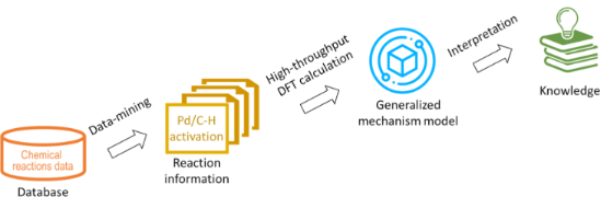
- functionalization of C–H bonds is a powerful strategy for the synthesis and derivatization of organic molecules [12]. Homogeneous catalysis employing transition metal complexes has been widely accepted as one of the most efficient ways to perform C–H activation-based synthesis with high selectivity under relatively

Graphical Abstract

Figure 1: An approximate energy map for the electrophilic aromatic substitution mechanism.

Scheme 1: Schematic representation of the two mechanisms of Pd-catalysed C–H activation reaction considered i...
An overview on disulfide-catalyzed and -cocatalyzed photoreactions
- Yeersen Patehebieke
Beilstein J. Org. Chem. 2020, 16, 1418–1435, doi:10.3762/bjoc.16.118

- , Cheng and co-workers reported a hydrodifluoroacetamidation of alkenes in which disulfide served as the photocatalyst with the Hantzsch ester as the reducing agent (Scheme 15) [23]. These reactions do not require costly transition-metal complexes, and they do not involve the oxidative regeneration of a

Graphical Abstract

Scheme 1: [3 + 2] cyclization catalyzed by diaryl disulfide.

Scheme 2: [3 + 2] cycloaddition catalyzed by disulfide.

Scheme 3: Disulfide-bridged peptide-catalyzed enantioselective cycloaddition.

Scheme 4: Disulfide-catalyzed [3 + 2] methylenecyclopentane annulations.

Scheme 5: Disulfide as a HAT cocatalyst in the [4 + 2] cycloaddition reaction.

Scheme 6: Proposed mechanism of the [4 + 2] cycloaddition reaction using disulfide as a HAT cocatalyst.

Scheme 7: Disulfide-catalyzed ring expansion of vinyl spiro epoxides.

Scheme 8: Disulfide-catalyzed aerobic oxidation of diarylacetylene.

Scheme 9: Disulfide-catalyzed aerobic photooxidative cleavage of olefins.

Scheme 10: Disulfide-catalyzed aerobic oxidation of 1,3-dicarbonyl compounds.

Scheme 11: Proposed mechanism of the disulfide-catalyzed aerobic oxidation of 1,3-dicarbonyl compounds.

Scheme 12: Disulfide-catalyzed oxidation of allyl alcohols.

Scheme 13: Disulfide-catalyzed diboration of alkynes.

Scheme 14: Dehalogenative radical cyclization catalyzed by disulfide.

Scheme 15: Hydrodifluoroacetamidation of alkenes catalyzed by disulfide.

Scheme 16: Plausible mechanism of the hydrodifluoroacetamidation of alkenes catalyzed by disulfide.

Scheme 17: Disulfide-cocatalyzed anti-Markovnikov olefin hydration reactions.

Scheme 18: Disulfide-catalyzed decarboxylation of carboxylic acids.

Scheme 19: Proposed mechanism of the disulfide-catalyzed decarboxylation of carboxylic acids.

Scheme 20: Disulfide-catalyzed decarboxylation of carboxylic acids.

Scheme 21: Disulfide-catalyzed conversion of maleate esters to fumarates and 5H-furanones.

Scheme 22: Disulfide-catalyzed isomerization of difluorotriethylsilylethylene.

Scheme 23: Disulfide-catalyzed isomerization of allyl alcohols to carbonyl compounds.

Scheme 24: Proposed mechanism for the disulfide-catalyzed isomerization of allyl alcohols to carbonyl compound...

Scheme 25: Diphenyl disulfide-catalyzed enantioselective synthesis of ophirin B.

Scheme 26: Disulfide-catalyzed isomerization in the total synthesis of (+)-hitachimycin.

Scheme 27: Disulfide-catalyzed isomerization in the synthesis of (−)-gloeosporone.
Photocatalysis with organic dyes: facile access to reactive intermediates for synthesis
- Stephanie G. E. Amos,
- Marion Garreau,
- Luca Buzzetti and
- Jerome Waser
Beilstein J. Org. Chem. 2020, 16, 1163–1187, doi:10.3762/bjoc.16.103

- growth resides in the availability of visible light-absorbing transition metal complexes. These catalysts can harvest the energy of visible-light photons and transfer it to organic molecules, giving access to key reactive intermediates. For instance, ruthenium and iridium polypyridyl complexes played a
- electronically excited species. These reactive intermediates are then used to forge new chemical bonds or to induce structural modifications within the organic substrates. The versatility of these metal complexes is due to their wide operational redox windows, which allows them to interact via their excited
- , the ability of transition metal complexes to intercept alkyl radicals has been exploited for expanding the possibility of C–C bond formation reactions to cross-couplings. In all of these transformations, the substituents on the alkyl radical determine if it reacts as a nucleophile or an electrophile

Graphical Abstract

Figure 1: Selected examples of organic dyes. Mes-Acr+: 9-mesityl-10-methylacridinium, DCA: 9,10-dicyanoanthra...

Scheme 1: Activation modes in photocatalysis.

Scheme 2: Main strategies for the formation of C(sp3) radicals used in organophotocatalysis.

Scheme 3: Illustrative example for the photocatalytic oxidative generation of radicals from carboxylic acids:...

Scheme 4: Illustrative example for the photocatalytic reductive generation of C(sp3) radicals from redoxactiv...

Figure 2: Common substrates for the photocatalytic oxidative generation of C(sp3) radicals.

Scheme 5: Illustrative example for the photocatalytic oxidative generation of radicals from dihydropyridines ...

Scheme 6: Illustrative example for the photocatalytic oxidative generation of C(sp3) radicals from trifluorob...

Scheme 7: Illustrative example for the photocatalytic reductive generation of C(sp3) radicals from benzylic h...

Scheme 8: Illustrative example for the photocatalytic generation of C(sp3) radicals via direct HAT: the cross...

Scheme 9: Illustrative example for the photocatalytic generation of C(sp3) radicals via indirect HAT: the deu...

Scheme 10: Selected precursors for the generation of aryl radicals using organophotocatalysis.

Scheme 11: Illustrative example for the photocatalytic reductive generation of aryl radicals from aryl diazoni...

Scheme 12: Illustrative examples for the photocatalytic reductive generation of aryl radicals from haloarenes:...

Scheme 13: Illustrative example for the photocatalytic reductive generation of aryl radicals from aryl halides...

Scheme 14: Illustrative example for the photocatalytic reductive generation of aryl radicals from arylsulfonyl...

Scheme 15: Illustrative example for the reductive photocatalytic generation of aryl radicals from triaryl sulf...

Scheme 16: Main strategies towards acyl radicals used in organophotocatalysis.

Scheme 17: Illustrative example for the decarboxylative photocatalytic generation of acyl radicals from α-keto...

Scheme 18: Illustrative example for the oxidative photocatalytic generation of acyl radicals from acyl silanes...

Scheme 19: Illustrative example for the oxidative photocatalytic generation of carbamoyl radicals from 4-carba...

Scheme 20: Illustrative example of the photocatalytic HAT approach for the generation of acyl radicals from al...

Scheme 21: General reactivity of a) radical cations; b) radical anions; c) the main strategies towards aryl an...

Scheme 22: Illustrative example for the oxidative photocatalytic generation of alkene radical cations from alk...

Scheme 23: Illustrative example for the reductive photocatalytic generation of an alkene radical anion from al...

Figure 3: Structure of C–X radical anions and their neutral derivatives.

Scheme 24: Illustrative example for the photocatalytic reduction of imines and the generation of an α-amino C(...

Scheme 25: Illustrative example for the oxidative photocatalytic generation of aryl radical cations from arene...

Scheme 26: NCR classifications and generation.

Scheme 27: Illustrative example for the photocatalytic reductive generation of iminyl radicals from O-aryl oxi...

Scheme 28: Illustrative example for the photocatalytic oxidative generation of iminyl radicals from α-N-oxy ac...

Scheme 29: Illustrative example for the photocatalytic oxidative generation of iminyl radicals via an N–H bond...

Scheme 30: Illustrative example for the photocatalytic oxidative generation of amidyl radicals from Weinreb am...

Scheme 31: Illustrative example for the photocatalytic reductive generation of amidyl radicals from hydroxylam...

Scheme 32: Illustrative example for the photocatalytic reductive generation of amidyl radicals from N-aminopyr...

Scheme 33: Illustrative example for the photocatalytic oxidative generation of amidyl radicals from α-amido-ox...

Scheme 34: Illustrative example for the photocatalytic oxidative generation of aminium radicals: the N-aryltet...

Scheme 35: Illustrative example for the photocatalytic oxidative generation of nitrogen-centered radical catio...

Scheme 36: Illustrative example for the photocatalytic oxidative generation of nitrogen-centered radical catio...

Scheme 37: Illustrative example for the photocatalytic oxidative generation of hydrazonyl radical from hydrazo...

Scheme 38: Generation of O-radicals.

Scheme 39: Illustrative examples for the photocatalytic generation of O-radicals from N-alkoxypyridinium salts...

Scheme 40: Illustrative examples for the photocatalytic generation of O-radicals from alkyl hydroperoxides: th...

Scheme 41: Illustrative example for the oxidative photocatalytic generation of thiyl radicals from thiols: the...

Scheme 42: Main strategies and reagents for the generation of sulfonyl radicals used in organophotocatalysis.

Scheme 43: Illustrative example for the reductive photocatalytic generation of sulfonyl radicals from arylsulf...

Scheme 44: Illustrative example of a Cl atom abstraction strategy for the photocatalytic generation of sulfamo...

Scheme 45: Illustrative example for the oxidative photocatalytic generation of sulfonyl radicals from sulfinic...

Scheme 46: Illustrative example for the photocatalytic generation of electronically excited triplet states: th...

Scheme 47: Illustrative example for the photocatalytic generation of electronically excited triplet states: th...
Development of fluorinated benzils and bisbenzils as room-temperature phosphorescent molecules
- Shigeyuki Yamada,
- Takuya Higashida,
- Yizhou Wang,
- Masato Morita,
- Takuya Hosokai,
- Kaveendra Maduwantha,
- Kaveenga Rasika Koswattage and
- Tsutomu Konno
Beilstein J. Org. Chem. 2020, 16, 1154–1162, doi:10.3762/bjoc.16.102

- ISC process, finally achieving an excellent light-emitting efficiency (up to 100%) [10]. Therefore, extensive investigations to develop phosphorescent molecules have been performed thus far [11][12][13]. It has been established that transition metal complexes containing a heavy atom can promote ISC

Graphical Abstract

Figure 1: (A) Transition-metal-containing and (B) pure organic phosphorescent materials reported thus far (bp...

Figure 2: (A) Chemical structures of fluorescent bistolane derivatives previously developed by our group and ...

Scheme 1: Synthetic pathway for fluorinated benzil (2) and bisbenzil (3) derivatives.

Scheme 2: Proposed mechanism of Pd(II)-catalyzed alkyne oxidation by dimethyl sulfoxide (DMSO).

Figure 3: Mulliken charge distributions of fluorinated 1a and nonfluorinated 1c obtained from density functio...

Figure 4: Absorption and photoluminescence (PL) spectra of (A) 2a, (B) 2b, (C) 3a, (D) 3b, and (E) 3c in tolu...

Figure 5: Distributions of molecular orbitals (isosurface value: 0.04 a.u.) involved in vertical electronic t...
Recent applications of porphyrins as photocatalysts in organic synthesis: batch and continuous flow approaches
- Rodrigo Costa e Silva,
- Luely Oliveira da Silva,
- Aloisio de Andrade Bartolomeu,
- Timothy John Brocksom and
- Kleber Thiago de Oliveira
Beilstein J. Org. Chem. 2020, 16, 917–955, doi:10.3762/bjoc.16.83

- aldehydes were obtained with excellent conversions (>99%) using this heterogeneous photocatalyst (Scheme 22). Metal complexes such as Pd and Pt porphyrins possess long-living triplet excited states and higher excited state potentials for oxidations [48]. In this regard, various benzoic acids were also

Graphical Abstract

Figure 1: Chemical structures of the porphyrinoids and their absorption spectra: in bold are highlighted the ...

Figure 2: Photophysical and photochemical processes (Por = porphyrin). Adapted from [12,18].

Figure 3: Main dual photocatalysts and their oxidative/reductive excited state potentials, including porphyri...

Scheme 1: Photoredox alkylation of aldehydes with diazo acetates using porphyrins and a Ru complex. aUsing a ...

Scheme 2: Proposed mechanism for the alkylation of aldehydes with diazo acetates in the presence of TPP.

Scheme 3: Arylation of heteroarenes with aryldiazonium salts using TPFPP as photocatalyst, and corresponding ...

Scheme 4: A) Scope with different aryldiazonium salts and enol acetates. B) Photocatalytic cycles and compari...

Scheme 5: Photoarylation of isopropenyl acetate A) Comparison between batch and continuous-flow approaches an...

Scheme 6: Dehalogenation induced by red light using thiaporphyrin (STPP).

Scheme 7: Applications of NiTPP as both photoreductant and photooxidant.

Scheme 8: Proposed mechanism for obtaining tetrahydroquinolines by reductive quenching.

Scheme 9: Selenylation and thiolation of anilines.

Scheme 10: NiTPP as photoredox catalyst in oxidative and reductive quenching, in comparison with other photoca...

Scheme 11: C–O bond cleavage of 1-phenylethanol using a cobalt porphyrin (CoTMPP) under visible light.

Scheme 12: Hydration of terminal alkynes by RhIII(TSPP) under visible light irradiation.

Scheme 13: Regioselective photocatalytic hydro-defluorination of perfluoroarenes by RhIII(TSPP).

Scheme 14: Formation of 2-methyl-2,3-dihydrobenzofuran by intramolecular hydro-functionalization of allylpheno...

Scheme 15: Photocatalytic oxidative hydroxylation of arylboronic acids using UNLPF-12 as heterogeneous photoca...

Scheme 16: Photocatalytic oxidative hydroxylation of arylboronic acids using MOF-525 as heterogeneous photocat...

Scheme 17: Preparation of the heterogeneous photocatalyst CNH.

Scheme 18: Photoinduced sulfonation of alkenes with sulfinic acid using CNH as photocatalyst.

Scheme 19: Sulfonic acid scope of the sulfonation reactions.

Scheme 20: Regioselective sulfonation reaction of arimistane.

Scheme 21: Synthesis of quinazolin-4-(3H)-ones.

Scheme 22: Selective photooxidation of aromatic benzyl alcohols to benzaldehydes using Pt/PCN-224(Zn).

Scheme 23: Photooxidation of benzaldehydes to benzoic acids using Pt or Pd porphyrins.

Scheme 24: Photocatalytic reduction of various nitroaromatics using a Ni-MOF.

Scheme 25: Photoinduced cycloadditions of CO2 with epoxides by MOF1.

Figure 4: Electronic configurations of the species of oxygen. Adapted from [66].

Scheme 26: TPP-photocatalyzed generation of 1O2 and its application in organic synthesis. Adapted from [67-69].

Scheme 27: Pericyclic reactions involving singlet oxygen and their mechanisms. Adapted from [67].

Scheme 28: First scaled up ascaridole preparation from α-terpinene.

Scheme 29: Antimalarial drug synthesis using an endoperoxidation approach.

Scheme 30: Photooxygenation of colchicine.

Scheme 31: Synthesis of (−)-pinocarvone from abundant (+)-α-pinene.

Scheme 32: Seeberger’s semi-synthesis of artemisinin.

Scheme 33: Synthesis of artemisinin using TPP and supercritical CO2.

Scheme 34: Synthesis of artemisinin using chlorophyll a.

Scheme 35: Quercitol stereoisomer preparation.

Scheme 36: Photocatalyzed preparation of naphthoquinones.

Scheme 37: Continuous endoperoxidation of conjugated dienes and subsequent rearrangements leading to oxidized ...

Scheme 38: The Opatz group total synthesis of (–)-oxycodone.

Scheme 39: Biomimetic syntheses of rhodonoids A, B, E, and F.

Scheme 40: α-Photooxygenation of chiral aldehydes.

Scheme 41: Asymmetric photooxidation of indanone β-keto esters by singlet oxygen using PTC as a chiral inducer...

Scheme 42: Asymmetric photooxidation of both β-keto esters and β-keto amides by singlet oxygen using PTC-2 as ...

Scheme 43: Bifunctional photo-organocatalyst used for the asymmetric oxidation of β-keto esters and β-keto ami...

Scheme 44: Mechanism of singlet oxygen oxidation of sulfides to sulfoxides.

Scheme 45: Controlled oxidation of sulfides to sulfoxides using protonated porphyrins as photocatalysts. aIsol...

Scheme 46: Photochemical oxidation of sulfides to sulfoxides using PdTPFPP as photocatalyst.

Scheme 47: Controlled oxidation of sulfides to sulfoxides using SnPor@PAF as a photosensitizer.

Scheme 48: Syntheses of 2D-PdPor-COF and 3D-Pd-COF.

Scheme 49: Photocatalytic oxidation of A) thioanisole to methyl phenyl sulfoxide and B) various aryl sulfides,...

Scheme 50: General mechanism for oxidation of amines to imines.

Scheme 51: Oxidation of secondary amines to imines.

Scheme 52: Oxidation of secondary amines using Pd-TPFPP as photocatalyst.

Scheme 53: Oxidative amine coupling using UNLPF-12 as heterogeneous photocatalyst.

Scheme 54: Synthesis of Por-COF-1 and Por-COF-2.

Scheme 55: Photocatalytic oxidation of amines to imines by Por-COF-2.

Scheme 56: Photocyanation of primary amines.

Scheme 57: Synthesis of ᴅ,ʟ-tert-leucine hydrochloride.

Scheme 58: Photocyanation of catharanthine and 16-O-acetylvindoline using TPP.

Scheme 59: Photochemical α-functionalization of N-aryltetrahydroisoquinolines using Pd-TPFPP as photocatalyst.

Scheme 60: Ugi-type reaction with 1,2,3,4-tetrahydroisoquinoline using molecular oxygen and TPP.

Scheme 61: Ugi-type reaction with dibenzylamines using molecular oxygen and TPP.

Scheme 62: Mannich-type reaction of tertiary amines using PdTPFPP as photocatalyst.

Scheme 63: Oxidative Mannich reaction using UNLPF-12 as heterogeneous photocatalyst.

Scheme 64: Transformation of amines to α-cyanoepoxides and the proposed mechanism.
Architecture and synthesis of P,N-heterocyclic phosphine ligands
- Wisdom A. Munzeiwa,
- Bernard Omondi and
- Vincent O. Nyamori
Beilstein J. Org. Chem. 2020, 16, 362–383, doi:10.3762/bjoc.16.35

- monitoring and in situ speciation. In addition, phosphine ligands have found various applications as auxiliary ligands in organometallic transition-metal complexes. A great number have exhibited potential application in organic light-emitting devices (OLEDs) [3], medicine [4][5][6] and catalysis [1][7][8
- [45][46]. The complimentary effect of P and N can help stabilizing different catalytic species that are produced during catalytic transformations [11][47]. P,N-phosphine ligands can effect regioselective control, due to the trans-effect as exhibited in π-allyl metal complexes, where substitution
- with aminosilanes which produces trimethylchlorosilane as a byproduct which can be distilled off easily [102]. Bicyclic guanidine frameworks present an opportunity to form inflexible ligands that are inclined to exhibit a κ2-P,N-bonding mode in metal complexes. Dyer et al. [103] prepared cycloguanidine

Graphical Abstract

Scheme 1: Synthesis of pyridylphosphine ligands.

Figure 1: Pyridylphosphine ligands.

Scheme 2: Synthesis of piperidyl- and oxazinylphosphine ligands.

Scheme 3: Synthesis of linear multi-chelate pyridylphosphine ligands.

Scheme 4: Synthesis of chiral acetal pyridylphosphine ligands.

Scheme 5: Synthesis of diphenylphosphine-substituted triazine ligands.

Scheme 6: Synthesis of (pyridine-2-ylmethyl)phosphine ligands.

Scheme 7: Synthesis of diphosphine pyrrole ligands.

Scheme 8: Synthesis of 4,5-diazafluorenylphosphine ligands.

Scheme 9: Synthesis of thioether-containing pyridyldiphosphine ligands starting from ethylene sulfide and dip...

Scheme 10: Synthesis of monoterpene-derived phosphine pyridine ligands.

Scheme 11: Synthesis of N-phenylphosphine-substituted imidazole ligands.

Scheme 12: Synthesis of triazol-4-ylphosphine ligands.

Scheme 13: Synthesis of phosphanyltriazolopyridines and product selectivity depending on the substituents’ eff...

Scheme 14: Synthesis of PTA-phosphine ligands.

Scheme 15: Synthesis of isomeric phosphine dipyrazole ligands by varying the reaction temperature.

Scheme 16: Synthesis of N-tethered phosphine imidazolium ligands (route A) and diphosphine imidazolium ligands...

Scheme 17: Synthesis of {1-[2-(pyridin-2-yl)- (R = CH) and {1-[2-(pyrazin-2-yl)quinazolin-4-yl]naphthalen-2-yl...

Scheme 18: Synthesis of oxazolylindolylphosphine ligands 102.

Scheme 19: Synthesis of pyrrolylphosphine ligands.

Scheme 20: Synthesis of phosphine guanidinium ligands.

Scheme 21: Synthesis of a polydentate aminophosphine ligand.

Scheme 22: Synthesis of quinolylphosphine ligands.

Scheme 23: Synthesis of N-(triazolylmethyl)phosphanamine ligands.

Figure 2: Triazolylphosphanamine ligands synthesized by Wassenaar’s method [22].

Scheme 24: Synthesis of oxazaphosphorines.

Scheme 25: Synthesis of paracyclophane pyridylphosphine ligands.

Scheme 26: Synthesis of triazolylphosphine ligands.

Figure 3: Click-phosphine ligands.

Scheme 27: Ferrocenyl pyridylphosphine imine ligands.

Scheme 28: Synthesis of phosphinooxazolines (PHOX).

Scheme 29: Synthesis of ferrocenylphosphine oxazoles.
Recent developments in photoredox-catalyzed remote ortho and para C–H bond functionalizations
- Rafia Siddiqui and
- Rashid Ali
Beilstein J. Org. Chem. 2020, 16, 248–280, doi:10.3762/bjoc.16.26

- = C, B, N, O, S) bonds for architecturally simple, yet challenging molecules, which are otherwise highly difficult or impossible to be formed by other methods. These practices count on the competence of metal complexes and organic dyes to convert visible light into chemical energy via SET events
- electron transfer and modification of the oxidation state of the transition metal complexes. Such systems can be combined with different metals, for example, Ni, Co, Cu, Ru, Ir, etc. However, unexpectedly, copper is less toxic and can be utilized to catalyze reactions without the requirement of a ligand
- still in its infancy. Nowadays, photoredox catalysis is on the forefront as a potent strategy for bond modifications through multicatalytic strategies and the invention of nontraditional methodologies. It is enormously effective in the generation of radicals by manipulating the transition metal

Graphical Abstract

Figure 1: List of photoredox catalysts used for C–H bond functionalizations.

Figure 2: List of metal-based photoredox catalysts used in this review article.

Figure 3: Jablonski diagram.

Figure 4: Photoredox catalysis via reductive or oxidative pathways. D = donor, A = acceptor, S = substrate, P...

Figure 5: Schematic representation of the combination of photoredox catalysis and transition metal catalysis.

Scheme 1: Weinreb amide C–H olefination.

Figure 6: Mechanism for the formation of 21 from 19 using photoredox catalyst 11.

Scheme 2: C–H olefination of phenolic ethers.

Scheme 3: Decarboxylative acylation of acetanilides.

Figure 7: Mechanism for the formation of 30 from acetanilide derivatives.

Scheme 4: Synthesis of fluorenone derivatives by intramolecular deoxygenative acylation of biaryl carboxylic ...

Figure 8: Mechanism for the photoredox-catalyzed synthesis of fluorenone derivatives.

Scheme 5: Synthesis of benzothiazoles via aerobic C–H thiolation.

Figure 9: Plausible mechanism for the construction of benzothiazoles from benzothioamides.

Scheme 6: Synthesis of benzothiazoles via oxidant-free C–H thiolation.

Figure 10: Mechanism involved in the synthesis of benzothiazoles via oxidant-free C–H thiolation.

Scheme 7: Synthesis of indoles via C–H cyclization of anilides with alkynes.

Scheme 8: Preparation of 3-trifluoromethylcoumarins via C–H cyclization of arylpropiolate esters.

Figure 11: Mechanistic pathway for the synthesis of coumarin derivatives via C–H cyclization.

Scheme 9: Monobenzoyloxylation without chelation assistance.

Figure 12: Plausible mechanism for the formation of 71 from 70.

Scheme 10: Aryl-substituted arenes prepared by inorganic photoredox catalysis using 12a.

Figure 13: Proposed mechanism for C–H arylations in the presence of 12a and a Pd catalyst.

Scheme 11: Arylation of purines via dual photoredox catalysis.

Scheme 12: Arylation of substituted arenes with an organic photoredox catalyst.

Scheme 13: C–H trifluoromethylation.

Figure 14: Proposed mechanism for the trifluoromethylation of 88.

Scheme 14: Synthesis of benzo-3,4-coumarin derivatives.

Figure 15: Plausible mechanism for the synthesis of substituted coumarins.

Scheme 15: Oxidant-free oxidative phosphonylation.

Figure 16: Mechanism proposed for the phosphonylation reaction of 100.

Scheme 16: Nitration of anilines.

Figure 17: Plausible mechanism for the nitration of aniline derivatives via photoredox catalysis.

Scheme 17: Synthesis of carbazoles via intramolecular amination.

Figure 18: Proposed mechanism for the formation of carbazoles from biaryl derivatives.

Scheme 18: Synthesis of substituted phenols using QuCN.

Figure 19: Mechanism for the synthesis of phenol derivatives with photoredox catalyst 8.

Scheme 19: Synthesis of substituted phenols with DDQ (5).

Figure 20: Possible mechanism for the generation of phenols with the aid of photoredox catalyst 5.

Scheme 20: Aerobic bromination of arenes using an acridinium-based photocatalyst.

Scheme 21: Aerobic bromination of arenes with anthraquinone.

Figure 21: Proposed mechanism for the synthesis of monobrominated compounds.

Scheme 22: Chlorination of benzene derivatives with Mes-Acr-MeClO4 (2).

Figure 22: Mechanism for the synthesis of 131 from 132.

Scheme 23: Chlorination of arenes with 4CzIPN (5a).

Figure 23: Plausible mechanism for the oxidative photocatalytic monochlorination using 5a.

Scheme 24: Monofluorination using QuCN-ClO4 (8).

Scheme 25: Fluorination with fluorine-18.

Scheme 26: Aerobic amination with acridinium catalyst 3a.

Figure 24: Plausible mechanism for the aerobic amination using acridinium catalyst 3a.

Scheme 27: Aerobic aminations with semiconductor photoredox catalyst 18.

Scheme 28: Perfluoroalkylation of arenes.

Scheme 29: Synthesis of benzonitriles in the presence of 3a.

Figure 25: Plausible mechanism for the synthesis of substituted benzonitrile derivatives in the presence of 3a....
Halogen-bonding-induced diverse aggregation of 4,5-diiodo-1,2,3-triazolium salts with different anions
- Xingyu Xu,
- Shiqing Huang,
- Zengyu Zhang,
- Lei Cao and
- Xiaoyu Yan
Beilstein J. Org. Chem. 2020, 16, 78–87, doi:10.3762/bjoc.16.10

- reported neutral 4-halo-1,2,3-triazolylidenes C [43], which had a carbene character with σ-donation at the carbon and a σ-hole at the halogen atom. XB is observed by single-crystal X-ray diffraction in their coinage metal complexes. Meanwhile, 4-bromo-1,2,3-triazolylidene can catalyze H/D exchange of

Graphical Abstract

Figure 1: 1,2,3-Triazole based XB donors: 1,2,3-triazole A, 1,2,3-triazolium B, 1,2,3-triazolylidene C and di...

Scheme 1: Synthesis of 4,5-diiodo-1,3-dimesityl-1,2,3-triazolium with iodide, Mes: 2,4,6-Me3C6H2.

Scheme 2: Synthesis of 4,5-diiodo-1,3-dimesityl-1,2,3-triazolium with different anion.

Figure 2: Packing structure of 2-I (top), 2-Br (middle) and 2-Cl (bottom). Hydrogen atoms have been omitted f...

Figure 3: Packing structure of 2-BF4. Hydrogen atoms have been omitted for clarity.

Figure 4: Packing structure of 2-OAc. Hydrogen atoms and solvent molecules have been omitted for clarity.

Figure 5: Packing structure of 2-TFA. Hydrogen atoms and disorder of fluorine atoms have been omitted for cla...

Figure 6: Packing structure of 2-I.1.5I2. Hydrogen atoms have been omitted for clarity.

Figure 7: Packing structure of 2-I.3.5I2. Hydrogen atoms have been omitted for clarity.

Figure 8: Packing structure of 2-BF4.0.5bpy. Hydrogen atoms and dichloromethane have been omitted for clarity....

Figure 9: 1,2,3-Triazole-based halogen model calculation: electrostatic potential surfaces mapped on total de...
A review of asymmetric synthetic organic electrochemistry and electrocatalysis: concepts, applications, recent developments and future directions
- Munmun Ghosh,
- Valmik S. Shinde and
- Magnus Rueping
Beilstein J. Org. Chem. 2019, 15, 2710–2746, doi:10.3762/bjoc.15.264

- corresponding bromo-cyclopropane 17 [24]. According to the authors, the passage of larger amounts of charge to facilitate product isolation might be responsible for the observed lower asymmetric yields. In 1998, Moutet’s group reported for the first time that transition metal complexes with chiral ligands can

Graphical Abstract

Figure 1: General classification of asymmetric electroorganic reactions.

Scheme 1: Asymmetric reduction of 4-acetylpyridine using a modified graphite cathode.

Scheme 2: Asymmetric hydrogenation of ketones using Raney nickel powder electrodes modified with optically ac...

Scheme 3: Asymmetric reduction of prochiral activated olefins with a poly-ʟ-valine-coated graphite cathode.

Scheme 4: Asymmetric reduction of prochiral carbonyl compounds, oximes and gem-dibromides on a poly-ʟ-valine-...

Scheme 5: Asymmetric hydrogenation of prochiral ketones with poly[RuIII(L)2Cl2]+-modified carbon felt cathode...

Scheme 6: Asymmetric hydrogenation of α-keto esters using chiral polypyrrole film-coated cathode incorporated...

Scheme 7: Quinidine and cinchonidine alkaloid-induced asymmetric electroreduction of acetophenone.

Scheme 8: Asymmetric electroreduction of 4- and 2-acetylpyridines at a mercury cathode in the presence of a c...

Scheme 9: Enantioselective reduction of 4-methylcoumarin in the presence of catalytic yohimbine.

Scheme 10: Cinchonine-induced asymmetric electrocarboxylation of 4-methylpropiophenone.

Scheme 11: Enantioselective hydrogenation of methyl benzoylformate using an alkaloid entrapped silver cathode.

Scheme 12: Alkaloid-induced enantioselective hydrogenation using a Cu nanoparticle cathode.

Scheme 13: Alkaloid-induced enantioselective hydrogenation of aromatic ketones using a bimetallic Pt@Cu cathod...

Scheme 14: Enantioselective reduction of ketones at mercury cathode using N,N'-dimethylquininium tetrafluorobo...

Scheme 15: Asymmetric synthesis of an amino acid using an electrode modified with amino acid oxidase and elect...

Scheme 16: Asymmetric oxidation of p-tolyl methyl sulfide using chemically modified graphite anode.

Scheme 17: Asymmetric oxidation of unsymmetric sulfides using poly(amino acid)-coated electrodes.

Scheme 18: Enantioselective, electocatalytic oxidative coupling on TEMPO-modified graphite felt electrode in t...

Scheme 19: Asymmetric electrocatalytic oxidation of racemic alcohols on a TEMPO-modified graphite felt electro...

Scheme 20: Asymmetric electrocatalytic lactonization of diols on TEMPO-modified graphite felt electrodes.

Scheme 21: Asymmetric electrochemical pinacolization in a chiral solvent.

Scheme 22: Asymmetric electroreduction using a chiral supporting electrolyte.

Scheme 23: Asymmetric anodic oxidation of enol acetates using chiral supporting electrolytes.

Scheme 24: Kinetic resolution of primary amines using a chiral N-oxyl radical mediator.

Scheme 25: Chiral N-oxyl-radical-mediated kinetic resolution of secondary alcohols via electrochemical oxidati...

Scheme 26: Chiral iodoarene-mediated asymmetric electrochemical lactonization.

Scheme 27: Os-catalyzed electrochemical asymmetric dihydroxylation of olefins using the Sharpless ligand and i...

Scheme 28: Asymmetric electrochemical epoxidation of olefins catalyzed by a chiral Mn-salen complex.

Scheme 29: Asymmetric electrooxidation of 1,2-diols, and amino alcohols using a chiral copper catalyst.

Scheme 30: Mechanism of asymmetric electrooxidation of 1,2-diols, and amino alcohols using a chiral copper cat...

Scheme 31: Enantioselective electrocarboxylation catalyzed by an electrogenerated chiral [CoI(salen)]− complex....

Scheme 32: Asymmetric oxidative cross coupling of 2-acylimidazoles with silyl enol ethers.

Scheme 33: Ni-catalyzed asymmetric electroreductive cleavage of allylic β-keto ester 89.

Scheme 34: Asymmetric alkylation using a combination of electrosynthesis and a chiral Ni catalyst.

Scheme 35: Mechanism of asymmetric alkylation using a combination of electrosynthesis and a chiral Ni catalyst....

Scheme 36: Asymmetric epoxidation by electrogenerated percarbonate and persulfate ions in the presence of chir...

Scheme 37: α-Oxyamination of aldehydes via anodic oxidation catalyzed by chiral secondary amines.

Scheme 38: The α-alkylation of aldehydes via anodic oxidation catalyzed by chiral secondary amines.

Scheme 39: Mechanism of α-alkylation of aldehydes via anodic oxidation catalyzed by chiral secondary amines.

Scheme 40: Electrochemical chiral secondary amine-catalyzed intermolecular α-arylation of aldehydes.

Scheme 41: Mechanism of electrochemical chiral secondary amine-catalyzed intermolecular α-arylation of aldehyd...

Scheme 42: Asymmetric cross-dehydrogenative coupling of tertiary amines with simple ketones via an electrochem...

Scheme 43: Electroenzymatic asymmetric reduction using enoate reductase.

Scheme 44: Assymetric reduction using alcohol dehydrogenase as the electrocatalyst.

Scheme 45: Asymmetric electroreduction catalyzed by thermophilic NAD-dependent alcohol dehydrogenase.

Scheme 46: Asymmetric epoxidation of styrene by electrochemical regeneration of flavin-dependent monooxygenase....

Scheme 47: Asymmetric electroreduction using a chloroperoxidase catalyst.

Scheme 48: Asymmetric electrochemical transformation mediated by hydrophobic vitamin B12.

Scheme 49: Diastereoselective cathodic reduction of phenylglyoxalic acids substituted with amines as chiral au...

Scheme 50: Ni-catalyzed asymmetric electroreductive cross coupling of aryl halides with α-chloropropanoic acid...

Scheme 51: Electrochemical Mannich addition of silyloxyfuran to in situ-generated N-acyliminium ions.

Scheme 52: Stereoselective electroreductive homodimerization of cinnamates attached to a camphor-derived chira...

Scheme 53: Diastereoselective electrochemical carboxylation of chiral α-bromocarboxylic acid derivatives.

Scheme 54: Electrocatalytic stereoselective conjugate addition of chiral β-dicarbonyl compounds to methyl viny...

Scheme 55: Stereoselective electrochemical carboxylation of chiral cinnamic acid derivatives under a CO2 atmos...

Scheme 56: Electrochemical diastereoselective α-alkylation of pyrrolidines attached with phosphorus-derived ch...

Scheme 57: Electrogenerated cyanomethyl anion-induced synthesis of chiral cis-β-lactams from amides bearing ch...

Scheme 58: Diastereoselective anodic oxidation followed by intramolecular cyclization of ω-hydroxyl amides bea...

Scheme 59: Electrochemical deprotonation of Ni(II) glycinate containing (S)-BPB as a chiral auxiliary: diaster...

Scheme 60: Enantioselective electroreductive coupling of diaryl ketones with α,β-unsaturated carbonyl compound...

Scheme 61: Asymmetric total synthesis of ropivacaine and its analogues using a electroorganic reaction as a ke...

Scheme 62: Asymmetric total synthesis of (−)-crispine A and its natural enantiomer via anodic cyanation of tet...

Scheme 63: Asymmetric oxidative electrodimerization of cinnamic acid derivatives as key step for the synthesis...
Fluorinated maleimide-substituted porphyrins and chlorins: synthesis and characterization
- Valentina A. Ol’shevskaya,
- Elena G. Kononova and
- Andrei V. Zaitsev
Beilstein J. Org. Chem. 2019, 15, 2704–2709, doi:10.3762/bjoc.15.263

- and their metal complexes are considered to be efficient precursors for design and selection of new PDT agents, since their reactivity toward various nucleophiles provides a simple, selective and general access to the functionalized derivatives [32][33][34]. Considering the promise of porphyrins and

Graphical Abstract

Scheme 1: Synthesis of fluorinated maleimide-substituted porphyrins 5a, 6, 7a, 7b, and 8.

Scheme 2: Synthesis of fluorinated maleimide-substituted chlorins 12,13.
Chiral terpene auxiliaries V: Synthesis of new chiral γ-hydroxyphosphine oxides derived from α-pinene
- Anna Kmieciak and
- Marek P. Krzemiński
Beilstein J. Org. Chem. 2019, 15, 2493–2499, doi:10.3762/bjoc.15.242

- research groups [1]. Compounds with a phosphorus atom attached to a stereogenic carbon center in acyclic and cyclic structures play an important role as chiral ligands in transition metal complexes [2]. They were applied to various catalytic asymmetric reactions [3][4], such as hydrogenations [3][4][5][6

Graphical Abstract

Scheme 1: Synthesis of (1R,2R,4S,5R)-3-methyleneneoisoverbanol (6).

Scheme 2: Synthesis of (1R,2R,3R,5R)-4-methyleneneoisopinocampheol (11).

Scheme 3: Synthesis of allylic alcohols 16 and 18 from β-pinene.

Figure 1: NOE effects in molecules 16 and 18.

Scheme 4: Synthesis of (1R,2R,3R,4R,5R)-3-((diphenylphosphanyl)methyl)isoverbanol (23).

Scheme 5: Synthesis of (((1R,2R,3S,4S,5S)-3-hydroxypinan-4-yl)methyl)diphenylphosphine oxide (27).

Scheme 6: Attempted sigmatropic rearrangement of phosphinites 28 and 29.
Anion-driven encapsulation of cationic guests inside pyridine[4]arene dimers
- Anniina Kiesilä,
- Jani O. Moilanen,
- Anneli Kruve,
- Christoph A. Schalley,
- Perdita Barran and
- Elina Kalenius
Beilstein J. Org. Chem. 2019, 15, 2486–2492, doi:10.3762/bjoc.15.241

- positive potential on the surface of the cavity, except on the N–H hydrogen atoms. They are, however, on tangential positions along the capsules surface, and therefore do not significantly contribute to anion binding [8]. More recently, we were also able to demonstrate that cationic transition metal
- complexes can template the formation of pyridinearene hexameric capsules in the gas phase [6]. Here, we report our novel findings on the ability of dimeric tetraisobutylpyridine[4]arene (compound 1 in Scheme 1) to encapsulate cationic guests. Despite of the obvious structural similarities between the

Graphical Abstract

Scheme 1: Structures of tetraisobutylpyridine[4]arene 1 and tetraisobutylresorcin[4]arene 2.

Figure 1: Spectra of 1 + Me4NPF6 1:3 in acetone in a) (+)ESI-MS and b) (−)ESI-MS. Insets showing arrival time...

Figure 2: (+)ESI-MS profile spectrum of the mixture of 1, 2 and TMAPF6 in acetonitrile (20 µM, 1:1:1). Inset ...

Figure 3: Calculated ESP surfaces (in au) superimposed on the total electron density (0.004 au) for 1 and 2: ...
Photochromic diarylethene ligands featuring 2-(imidazol-2-yl)pyridine coordination site and their iron(II) complexes
- Andrey G. Lvov,
- Max Mörtel,
- Anton V. Yadykov,
- Frank W. Heinemann,
- Valerii Z. Shirinian and
- Marat M. Khusniyarov
Beilstein J. Org. Chem. 2019, 15, 2428–2437, doi:10.3762/bjoc.15.235

- ligand. The bridging nature of the diarylethene in the complexes prevents photocyclization. Keywords: diarylethene; 2-(imidazol-2-yl)pyridine; iron(II) complex; photochromism; Introduction Transition metal complexes with photoactive ligands are of great interest for advanced photonic applications [1][2
- ligands with pendant coordination sites were synthesized, which allowed the remote control of luminescent, nonlinear optical and magnetic properties of transition metal complexes to some extent [11][12][13][14][15][16]. However, a close arrangement of hexatriene and coordination sites is the preferred

Graphical Abstract

Figure 1: Families of diarylethene-bases ligands with spatial proximity of coordination site (blue) and photo...

Scheme 1: Synthesis of photochromic ligands.

Figure 2: Electronic spectra of diarylethene 6 upon UV irradiation (313 nm, toluene, c = 3.4 × 10⁻⁵ M). Inset...

Scheme 2: Reversible photocyclization of ligand 6.

Figure 3: Molecular structure of complexes 8 (top) and 9 (bottom) at 100 K. The H atoms are omitted for clari...

Figure 4: Variable temperature χT product (blue) and χ (green) of 8 (top) and 9 (bottom) measured at an exter...
1,2,3-Triazolium macrocycles in supramolecular chemistry
- Mastaneh Safarnejad Shad,
- Pulikkal Veettil Santhini and
- Wim Dehaen
Beilstein J. Org. Chem. 2019, 15, 2142–2155, doi:10.3762/bjoc.15.211

- mechanically interlocked molecules and molecular machines. We will not concern ourselves in this review with the applications of metal complexes based on N-heterocyclic carbene coordination chemistry, derived of triazoliums or with applications as ionic liquids [26][27][28]. 2. Anion recognition Due to the

Graphical Abstract

Figure 1: Hydrogen, halogen or chalcogen bonding to anions within a bistriazolium macrocycle.

Figure 2: Main synthetic strategies towards macrocyclic triazoliums.

Figure 3: Chemical structure of compound 1 (1a, 1b and 1c) and 2.

Figure 4: Chemical structure of compound 3 and 4.

Figure 5: Chemical structure of compound 5.

Figure 6: Chemical structure of compound 6.

Figure 7: Chemical structure of compound 7.

Figure 8: Chemical structure of compound 8.

Figure 9: Chemical structures of compound 9.

Figure 10: Chemical structures of compound 10, 11 and 12.

Figure 11: Chemical structure of compound 13.

Figure 12: Chemical structure of compound 15 including the sigma-connected TCNQ dimer.

Figure 13: Chemical structure of compound 16 for the kinetic resolution of epoxides.

Figure 14: Chemical structure of compound 17a (bisnaphtho crown ether shown).

Figure 15: Jump rope in molecular double-lasso compounds 18.

Figure 16: Chemical structure of compound 19 and acid–base triggered motions.