Search results
Search for "sputtering" in Full Text gives 356 result(s) in Beilstein Journal of Nanotechnology. Showing first 200.
Nanoporous water oxidation electrodes with a low loading of laser-deposited Ru/C exhibit enhanced corrosion stability
Beilstein J. Nanotechnol. 2019, 10, 157–167, doi:10.3762/bjnano.10.15

- ), which are due to the Ru/C layer and adventitious carbon. Argon ion sputtering results in a reduced carbon content (observable in both the C 1s and O 1s regions), as well as in a shift of the Ru 3d doublet of peaks to lower binding energies (Figure 8b and Figure S4, Supporting Information File 1). Thus
- system with a base pressure of 10−9 mbar. Adventitious carbon was removed from the surface by 1 min, 2 kV Ar+ ion sputtering. To prevent charging a combination of electron and ion neutralization was employed. The Ru 3d and O 1s XPS core level spectra were analyzed using a fitting routine which decomposes
- precursor Ru3(CO)12 (b). X-ray photoelectron spectra of a nanostructured Ru/C sample recorded as deposited and after Ar+ sputtering. All spectra are shifted to a C 1s binding energy position of 284.4 eV. (a) Survey spectra showing the expected elements. (b) Ru 3d region, which is superimposed with the C 1s


Sputtering of silicon nanopowders by an argon cluster ion beam
Beilstein J. Nanotechnol. 2019, 10, 135–143, doi:10.3762/bjnano.10.13

- pressed Si nanopowder targets consisting of particles with a mean diameter of 60 nm. The influence of the target density and the cluster ion beam parameters (energy and dose) on the sputtering depth and sputtering yield was studied. The sputtering yield was found to decrease with increasing dose and
- target density. The energy dependence demonstrated an unusual non-monotonic behavior. At 17.3 keV a maximum of the sputtering yield was observed, which was more than forty times higher than that of the bulk Si. The surface roughness at low energy demonstrates a similar energy dependence with a maximum
- near 17 keV. The dose and energy dependence of the sputtering yield was explained by the competition of the finite size effect and the effect of debris formation. Keywords: finite size effect; gas cluster ion beam; silicon nanoparticles; smoothing effect; sputtering; Introduction Etching using gas


Zn/F-doped tin oxide nanoparticles synthesized by laser pyrolysis: structural and optical properties
Beilstein J. Nanotechnol. 2019, 10, 9–21, doi:10.3762/bjnano.10.2

- atom %) made by spray pyrolysis showing high transparency and bandgap values between 3.86 and 4.45 eV have also been reported [32]. Other researchers have used radio frequency magnetron sputtering of mixed 30 wt % ZnO and 70 wt % SnO2 targets to obtain similar FZTO films, yet their reported different


Apparent tunneling barrier height and local work function of atomic arrays
Beilstein J. Nanotechnol. 2018, 9, 3048–3052, doi:10.3762/bjnano.9.283

- operated at 4.5 K. Cu(111) surfaces were cleaned by Ar+ sputter/anneal cycles. W tips were electrochemically etched from polycrystalline wire. After sputtering, they were further prepared in situ by indenting them into the Cu(111) substrate. Because of this procedure, the tips were presumably covered with


Femtosecond laser-assisted fabrication of chalcopyrite micro-concentrator photovoltaics
Beilstein J. Nanotechnol. 2018, 9, 3025–3038, doi:10.3762/bjnano.9.281
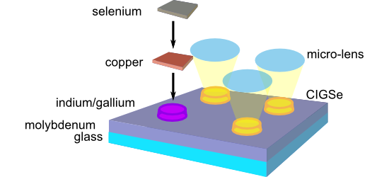
- . Subsequently, ZnO and finally Al:ZnO layers were created in a sputtering process. Details for CdS and ZnO/Al:ZnO deposition can be found in [25]. Figure 13 shows an SEM image of the edge of a CISe micro island, which has been processed according to this procedure, i.e., in a state corresponding to Figure 12d
- . B. Heidmann and M. Schmid are grateful to the Helmholtz Association for support from the Initiative and Networking Fund for the Young Investigator Group VH-NG-928. The authors would like to thank M. Kirsch for ZnO sputtering and grid deposition.


Electrostatic force microscopy for the accurate characterization of interphases in nanocomposites
Beilstein J. Nanotechnol. 2018, 9, 2999–3012, doi:10.3762/bjnano.9.279

- nm) were deposited or grown over the whole sample surface. Aluminum oxide (Al2O3) shells were prepared using the atomic layer deposition (ALD) method, polyvinyl acetate (PVAc) shells by spin coating, and silicon dioxide (SiO2) shells by plasma sputtering deposition (PSD). The signature of each
- during sputtering [48]. This result was also verified for superimposed planar films, as deduced from the bottom regions of the sample (Figure 9b). In [38], we also tested these findings on entirely planar samples. Nevertheless, these hypotheses on the SiO2 surface emphasize the need for better
- ). Silicon dioxide layers were deposited by plasma sputtering in a Plassys 450S reactor using a high purity SiO2 target source. The deposition regime included a preliminary exposure to 100 sccm argon plasma at 50 W for 20 s, while substrates and SiO2 target samples were screened. Then, the target shutter was


Size limits of magnetic-domain engineering in continuous in-plane exchange-bias prototype films
Beilstein J. Nanotechnol. 2018, 9, 2968–2979, doi:10.3762/bjnano.9.276

- prototypical in-plane EB layer system Ir17Mn83 (30 nm)/Co70Fe30 (10 nm) was grown by RF sputtering at a power of 160 W and an argon gas flux of 155 sccm on a naturally oxidized 5 nm × 5 nm Si(100) wafer, with Cu (5 nm) buffer and Ta (10 nm) capping. EB at the interface between the antiferromagnetic (AF) and
- performed at beamline UE56/1-SGM of the synchrotron radiation facility BESSY II after excitation with right and left circularly polarized X-rays with an energy of 709 eV (Fe L3 edge). Prior to measurements, the capping layer was thinned by argon ion sputtering allowing the Fe photoelectrons to escape from


![[Graphic 63]](/bjnano/content/inline/2190-4286-9-276-i63.svg?max-width=637&scale=1.18182) .
. ![[Graphic 64]](/bjnano/content/inline/2190-4286-9-276-i64.svg?max-width=637&scale=1.18182) is the angle between the domain wall (DW) normal vector
is the angle between the domain wall (DW) normal vector ![[Graphic 65]](/bjnano/content/inline/2190-4286-9-276-i65.svg?max-width=637&scale=1.18182) and the local unidirectio...
and the local unidirectio...
Investigation of CVD graphene as-grown on Cu foil using simultaneous scanning tunneling/atomic force microscopy
Beilstein J. Nanotechnol. 2018, 9, 2953–2959, doi:10.3762/bjnano.9.274

- conduct simultaneous STM/AFM measurements. This system with a sensitivity of 2·10−4 Å/√Hz is capable of measuring tunnel current, force, force gradient, tunnel barrier height and energy loss [32]. The UHV chamber is equipped with an argon sputtering gun and a resistive heater that could be used for sample


Site-controlled formation of single Si nanocrystals in a buried SiO2 matrix using ion beam mixing
Beilstein J. Nanotechnol. 2018, 9, 2883–2892, doi:10.3762/bjnano.9.267

- -oxide-semiconductor (CMOS) technology and thus have yet to be integrated into a cost-efficient Si-based technology. Multiple methods have been proposed and optimized for Si NC fabrication, including plasma-enhanced chemical vapor deposition (PECVD) [4][10], magnetron sputtering [11][12], laser-induced
- fluence over 10000 Ne+/nm2 in order to achieve a sufficient Si enrichment in the SiO2 layer. Two effects prevent NC self-assembly by point irradiation. First, the sputtering of the top silicon layer becomes significant. Second, Ne bubble formation [34][35] occurred below the SiO2 layer resulting in a
- position of the focused beam irradiation and has a diameter of 2.2 nm. Further minimization of the mixed volume by point-like irradiation with the focused Ne+ ion beam is prohibited by excessive sputtering and Ne bubble formation due to the high fluences required to achieve sufficient mixing. However, the


Charged particle single nanometre manufacturing
Beilstein J. Nanotechnol. 2018, 9, 2855–2882, doi:10.3762/bjnano.9.266

- the resist through sputtering and loss of substrate crystallinity. The situation for Ga+ ions is further complicated by the property of Ga+ as a p-type dopant of silicon. Scattering and range can be calculated using Monte Carlo simulation codes with typical results as shown in Figure 3 [30]. The
- , complementary to EBID in that it is top-down, with a significant advantage over ion milling due to the absence of sputtering. It therefore has wide applications, including use on samples that cannot withstand ion exposure, e.g., due to damage susceptibility. The first report of EBIE to our knowledge was in 1979


Controlling surface morphology and sensitivity of granular and porous silver films for surface-enhanced Raman scattering, SERS
Beilstein J. Nanotechnol. 2018, 9, 2813–2831, doi:10.3762/bjnano.9.263

- treatment; silver; sputtering; surface-enhanced Raman spectroscopy (SERS); surface roughening; Introduction The great enhancement of Raman signals obtained from molecules when they are in close vicinity to a rough noble-metal surface (e.g., gold, silver and copper) has attracted a great deal of interest in
- Electronics) scanning Auger nanoprobe operated at an acceleration voltage of 20 keV and a current of 10 nA. Sputtering was carried out under ultra-high vacuum (5 × 10⁻⁹ Torr), with an argon gun operated at 250 eV and 500 nA. The UV–vis spectra of the silver films on glass substrate were recorded by a Thermo
- are observed due island formation during sputtering (Figure 1c,d) [77]. The granular morphology could be advantageous for the formation of hot spots resulting in an efficient SERS activity of the silver film. For the 200 nm thick silver film the coalescence of the adjacent silver clusters formed in


Variation of the photoluminescence spectrum of InAs/GaAs heterostructures grown by ion-beam deposition
Beilstein J. Nanotechnol. 2018, 9, 2794–2801, doi:10.3762/bjnano.9.261

- photoluminescence spectrum of the heterostructures. The heterostructures were synthesized by using an IBD system [21]. The deposition experiments were performed on GaAs(100) substrates. The deposition of the material was carried out by sputtering the target with an Ar+ ion beam. Calibration dependencies of InAs and
- GaAs sputtering yields on the beam energy, the slope angle and the flux density were obtained earlier [21][49][50]. Two types of samples were grown for the research of vertically stacked QDs. The first type of samples (ST#1) contained one to three QD layers separated by 15 nm GaAs layers. The second
- sputtering yield of the target, which affects the kinetics of the surface processes on the substrate. The influence of the thickness of the i-GaAs barrier layer (ST#2 samples) on the photoluminescence properties of the InAs/GaAs heterostructures is shown in Figure 2. It is seen that a decrease in the i-GaAs


Optimization of Mo/Cr bilayer back contacts for thin-film solar cells
Beilstein J. Nanotechnol. 2018, 9, 2700–2707, doi:10.3762/bjnano.9.252

- chromium (Cr) adhesion layer is used as the back contact for a copper zinc tin sulfide (CZTS) thin-film solar cell on a SLG substrate. DC magnetron sputtering is used for deposition of Mo and Cr films. The conductivity of Mo/Cr bilayer films, their microstructure and surface morphology are studied at
- ; bilayer; chromium; DC sputtering; molybdenum; optical reflectance; Introduction Molybdenum (Mo) thin films are widely used as a back contact for photovoltaic devices such as Cu(In1−xGax)S2 (CIGS) and Cu2ZnSnS4 (CZTS) thin-film solar cells. The back contact is the first layer to be deposited and its
- a functions of the sputtering power and pressure [8][9]. The most successful approach suggested so far to improve the adhesion of Mo back contact layer to the glass substrate (while retaining its conductivity and optical reflectance) is through the deposition of a Mo bilayer rather than a single


Au–Si plasmonic platforms: synthesis, structure and FDTD simulations
Beilstein J. Nanotechnol. 2018, 9, 2599–2608, doi:10.3762/bjnano.9.241

- . Experimental Au nanostructures were prepared on Si(111) as a substrate. The substrates (1 × 1 cm2 of area) were cleaned with acetylacetone and then rinsed in ethanol. Thin Au films (with thicknesses in a range of 1.7–5.0 nm) were deposited using a table-top dc magnetron sputtering coater (EM SCD 500, Leica


Pattern generation for direct-write three-dimensional nanoscale structures via focused electron beam induced deposition
Beilstein J. Nanotechnol. 2018, 9, 2581–2598, doi:10.3762/bjnano.9.240

- sputtering to a thickness of 30 nm and 3 nm, respectively. The patterning was done by UV lithography using allresist AR-U 4040 and lift-off. In section 3.5 we state some of the execution times for the generation of the pattern files used for deposit fabrication as presented next. 3.1 Edge-angle-dependent


Exploring the photoleakage current and photoinduced negative bias instability in amorphous InGaZnO thin-film transistors with various active layer thicknesses
Beilstein J. Nanotechnol. 2018, 9, 2573–2580, doi:10.3762/bjnano.9.239

- thicknesses were prepared by magnetron sputtering. The initial electrical properties and the photoleakage current of a-IGZO TFTs with various active layer thicknesses were investigated. The subthreshold value slightly increased while the threshold voltage (Vth) and mobility (μ) decreased with increasing TIGZO
- at 160 °C from a sintered IGZO ceramic target by DC magnetron sputtering with a mixed gas of Ar/O2 = 29.4/0.6 sccm at a deposition pressure of 1 Pa. After patterning of the IGZO films as the active channel, a SiOx etch-stopper (200 nm), source and drain electrodes, and a 200 nm-thick SiOx passivation


High-temperature magnetism and microstructure of a semiconducting ferromagnetic (GaSb)1−x(MnSb)x alloy
Beilstein J. Nanotechnol. 2018, 9, 2457–2465, doi:10.3762/bjnano.9.230

- , Russian Federation 10.3762/bjnano.9.230 Abstract We have studied the properties of relatively thick (about 120 nm) magnetic composite films grown by pulsed laser deposition using the eutectic compound (GaSb)0.59(MnSb)0.41 as target for sputtering. For the studied films we have observed ferromagnetism and
- , using a GaSb–MnSb eutectic composition as a target for sputtering allowed us to avoid the formation of MnGa inclusions, which were observed earlier in samples obtained by laser deposition from Mn and GaSb targets, without taking the stoichiometry into account [28]. However, due to unevenness of the film


Thickness-dependent photoelectrochemical properties of a semitransparent Co3O4 photocathode
Beilstein J. Nanotechnol. 2018, 9, 2432–2442, doi:10.3762/bjnano.9.228

- favourable HER properties [20]. We also developed compact Co3O4 films by a reactive sputtering method, in which sputtered Co particles were converted into a compact Co3O4 film by controlling the flowing O2 gas, to offer a self-powered ultraviolet photodetector [17] and semitransparent photovoltaics [39]. It
- thickness were deposited using large-area (4 inch diameter) sputtering on glass and FTO/glass substrates. Identical rapid thermal processing (RTP) oxidation was applied to these Co films to allow the formation of Co3O4 films of varying thickness and porosity. Figure 1b shows the XRD pattern of two prepared
- Co3O4 film are primarily due to its enhanced porosity and optical absorption. We also studied the thickness dependent optical and electrical properties of Co3O4 film grown by reactive sputtering [17]. In fact, we can see the systematic variation of Mott–Schottky characteristics, and so of the VFB and NA


ZnO-nanostructure-based electrochemical sensor: Effect of nanostructure morphology on the sensing of heavy metal ions
Beilstein J. Nanotechnol. 2018, 9, 2421–2431, doi:10.3762/bjnano.9.227

- carried out with the LAB18 thin film deposition system (Kurt J. Lesker, USA) in DC magnetron sputtering mode. As a result, a set of electrodes consisted of four mutually separated planar elements, as illustrated in Figure 1. All of the manipulations described below were carried out using a metal mask


Magnetism and magnetoresistance of single Ni–Cu alloy nanowires
Beilstein J. Nanotechnol. 2018, 9, 2345–2355, doi:10.3762/bjnano.9.219

- 620 equipment situated into a cleanroom class 100 (ISO EN 14644) with RF magnetron sputtering and thermal vacuum evaporation (using TECTRA equipment). Thus, to contact single Ni–Cu alloy nanowires using a typical EBL process (Zeiss Merlin Compact field-emission scanning electron microscope combined
- , the deposition of Ti and Au contacts (100/200 nm) by RF magnetron sputtering and thermal vacuum evaporation, respectively, was performed. Individual contacted Ni–Cu alloy nanowires are thus obtained. The main steps of the EBL process are shown in Figure 8. The morphological and compositional


Influence of the thickness of an antiferromagnetic IrMn layer on the static and dynamic magnetization of weakly coupled CoFeB/IrMn/CoFeB trilayers
Beilstein J. Nanotechnol. 2018, 9, 2198–2208, doi:10.3762/bjnano.9.206

- (10 nm) were deposited at room temperature using pulsed-DC magnetron sputtering on naturally oxidized Si wafers with Ta (5 nm) seed and cap layers. The base pressure and working pressure of deposition were 2·10−7 and 4·10−3 Torr, respectively. The thickness tIrMn was systematically varied in 1 nm


Electrospun one-dimensional nanostructures: a new horizon for gas sensing materials
Beilstein J. Nanotechnol. 2018, 9, 2128–2170, doi:10.3762/bjnano.9.202

- fabrication strategy for synthesis of SnO2 NFs with a branch-on-stem morphology using electrospinning, oxygen plasma etching, sputtering and annealing. Electrospun PVP NFs were first etched with oxygen plasma to make a hierarchical template. Afterwards, a SnO2 film is deposited by sputtering and the PVP
- template is removed by annealing. The morphology of the NFs is dependent on sputtering time, resulting in uniformly distributed branches all over stem. Jun et al. [77] developed polypyrrole (PPy)-coated SnO2 tube-in-tube structures using single-nozzle electrospinning with a phase separation solvent method


A scanning probe microscopy study of nanostructured TiO2/poly(3-hexylthiophene) hybrid heterojunctions for photovoltaic applications
Beilstein J. Nanotechnol. 2018, 9, 2087–2096, doi:10.3762/bjnano.9.197

- knowledge, this joint KPFM/PC-AFM study of such a nanostructured array of TiO2 columns sensitized with functionalized P3HT-COOH constitutes a novel result of interest from both a theoretical and material design perspectives. Materials and Methods The TiO2 layers were synthesized by magnetron sputtering in


High-throughput synthesis of modified Fresnel zone plate arrays via ion beam lithography
Beilstein J. Nanotechnol. 2018, 9, 2049–2056, doi:10.3762/bjnano.9.194

- sputtering processes. The idea here is, if the desired depth of an open zone can be reached before destroying the adjacent zones, it becomes possible to write very dense structures, very quickly. To achieve this goal, the ion beam dosage, which is now determined by the 1D beam overlap (i.e., the step size in


Metal-free catalysis based on nitrogen-doped carbon nanomaterials: a photoelectron spectroscopy point of view
Beilstein J. Nanotechnol. 2018, 9, 2015–2031, doi:10.3762/bjnano.9.191

- kinetic energies from hundreds of electronvolts to few kiloelectronvolts does not lead to a damage or the sputtering of the material [37][57][84][85]. This effect was explained with different dissipation of the ion energy in the nanostructured material compared to the bulk. In the former, many ions
- traverse the nanostructures without inelastic scattering, while for bulk materials or graphene supported on heavy metallic substrates, the energy of the incident ion species is dissipated at the surface generating a backscattering cascade leading to the sputtering of the sample surface (Figure 5). Using


