Search for "additives" in Full Text gives 354 result(s) in Beilstein Journal of Organic Chemistry. Showing first 200.
Beilstein J. Org. Chem. 2020, 16, 1805–1819, doi:10.3762/bjoc.16.148
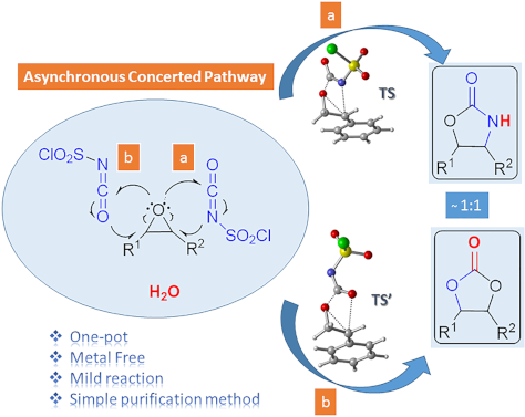
Graphical Abstract
Scheme 1: Oxazolidinone (1), five-membered cyclic carbonate (2) and some important compounds containing an ox...
Scheme 2: Proposed mechanisms by Keshava Murthy and Dhar [41] and De Meijere and co-workers [42].
Figure 1: Possible pathways for the formation of oxazolidinone intermediates 10 and 11. Optimized transition ...
Figure 2: Potential energy profile related to the formation of oxazolidinone intermediates 10 and 11 at the P...
Figure 3: IRC calculated for the formation of (a) 10 and (b) 11 at M06-2X/6-31+G(d,p) level. I-1, I-15, I-35, ...
Figure 4: Optimized geometries for the stationary points for the formation of 10 at PCM(DCM)/M06-2X/6-31+G(d,...
Scheme 3: Proposed mechanisms for the formation of oxazolidinone 9f.
Figure 5: Potential energy profiles for paths 1a (blue), 1b (red), 2 (green) and relative Gibbs free energies...
Figure 6: Optimized geometries for the stationary points of path 1b at PCM(DCM)/M06-2X/6-31+G(d,p)//M06-2X/6-...
Scheme 4: Proposed mechanism for the formation of five-membered cyclic carbonate 8f.
Figure 7: Potential energy profile and relative Gibbs free energies (kcal/mol) in DCM related to the formatio...
Figure 8: Optimized geometries for the stationary points of step 1 for the formation of 16 at PCM(DCM)/M06-2X...
Figure 9: Optimized geometries for the stationary points of step 2 for the formation of 17 at PCM(DCM)/M06-2X...
Figure 10: Optimized geometries for the stationary points of step 3 for the formation of PC8 at PCM(DCM)/M06-2...
Beilstein J. Org. Chem. 2020, 16, 1754–1804, doi:10.3762/bjoc.16.147
Graphical Abstract
Figure 1: Concept of dual synergistic catalysis.
Figure 2: Classification of catalytic systems involving two catalysts.
Figure 3: General mechanism for the dual nickel/photoredox catalytic system.
Figure 4: General mechanisms for C–H activation catalysis involving different reoxidation strategies.
Figure 5: Indole synthesis via dual C–H activation/photoredox catalysis.
Figure 6: Proposed mechanism for the indole synthesis via dual catalysis.
Figure 7: Oxidative Heck reaction on arenes via the dual catalysis.
Figure 8: Proposed mechanism for the Heck reaction on arenes via dual catalysis.
Figure 9: Oxidative Heck reaction on phenols via the dual catalysis.
Figure 10: Proposed mechanism for the Heck reaction on phenols via dual catalysis.
Figure 11: Carbazole synthesis via dual C–H activation/photoredox catalysis.
Figure 12: Proposed mechanism for the carbazole synthesis via dual catalysis.
Figure 13: Carbonylation of enamides via the dual C–H activation/photoredox catalysis.
Figure 14: Proposed mechanism for carbonylation of enamides via dual catalysis.
Figure 15: Annulation of benzamides via the dual C–H activation/photoredox catalysis.
Figure 16: Proposed mechanism for the annulation of benzamides via dual catalysis.
Figure 17: Synthesis of indoles via the dual C–H activation/photoredox catalysis.
Figure 18: Proposed mechanism for the indole synthesis via dual catalysis.
Figure 19: General concept of dual catalysis merging C–H activation and photoredox catalysis.
Figure 20: The first example of dual catalysis merging C–H activation and photoredox catalysis.
Figure 21: Proposed mechanism for the C–H arylation with diazonium salts via dual catalysis.
Figure 22: Dual catalysis merging C–H activation/photoredox using diaryliodonium salts.
Figure 23: Direct arylation via the dual catalytic system reported by Xu.
Figure 24: Direct arylation via dual catalytic system reported by Balaraman.
Figure 25: Direct arylation via dual catalytic system reported by Guo.
Figure 26: C(sp3)–H bond arylation via the dual Pd/photoredox catalytic system.
Figure 27: Acetanilide derivatives acylation via the dual C–H activation/photoredox catalysis.
Figure 28: Proposed mechanism for the C–H acylation with α-ketoacids via dual catalysis.
Figure 29: Acylation of azobenzenes via the dual catalysis C–H activation/photoredox.
Figure 30: C2-acylation of indoles via the dual C–H activation/photoredox catalysis.
Figure 31: Proposed mechanism for the C2-acylation of indoles with aldehydes via dual catalysis.
Figure 32: C2-acylation of indoles via the dual C–H activation/photoredox catalysis.
Figure 33: Perfluoroalkylation of arenes via the dual C–H activation/photoredox catalysis.
Figure 34: Proposed mechanism for perfluoroalkylation of arenes via dual catalysis.
Figure 35: Sulfonylation of 1-naphthylamides via the dual C–H activation/photoredox catalysis.
Figure 36: Proposed mechanism for sulfonylation of 1-naphthylamides via dual catalysis.
Figure 37: meta-C–H Alkylation of arenes via visible-light metallaphotocatalysis.
Figure 38: Alternative procedure for meta-C–H alkylation of arenes via metallaphotocatalysis.
Figure 39: Proposed mechanism for meta-C–H alkylation of arenes via metallaphotocatalysis.
Figure 40: C–H borylation of arenes via visible-light metallaphotocatalysis.
Figure 41: Proposed mechanism for C–H borylation of arenes via visible-light metallaphotocatalysis.
Figure 42: Undirected C–H aryl–aryl cross coupling via dual gold/photoredox catalysis.
Figure 43: Proposed mechanism for the undirected C–H aryl–aryl cross-coupling via dual catalysis.
Figure 44: Undirected C–H arylation of (hetero)arenes via dual manganese/photoredox catalysis.
Figure 45: Proposed mechanism for the undirected arylation of (hetero)arenes via dual catalysis.
Figure 46: Photoinduced C–H arylation of azoles via copper catalysis.
Figure 47: Photo-induced C–H chalcogenation of azoles via copper catalysis.
Figure 48: Decarboxylative C–H adamantylation of azoles via dual cobalt/photoredox catalysis.
Figure 49: Proposed mechanism for the C–H adamantylation of azoles via dual catalysis.
Figure 50: General mechanisms for the “classical” (left) and Cu-free variant (right) Sonogoshira reaction.
Figure 51: First example of a dual palladium/photoredox catalysis for Sonogashira-type couplings.
Figure 52: Arylation of terminal alkynes with diazonium salts via dual gold/photoredox catalysis.
Figure 53: Proposed mechanism for the arylation of terminal alkynes via dual catalysis.
Figure 54: C–H Alkylation of alcohols promoted by H-atom transfer (HAT).
Figure 55: Proposed mechanism for the C–H alkylation of alcohols promoted by HAT.
Figure 56: C(sp3)–H arylation of latent nucleophiles promoted by H-atom transfer.
Figure 57: Proposed mechanism for the C(sp3)–H arylation of latent nucleophiles promoted by HAT.
Figure 58: Direct α-arylation of alcohols promoted by H-atom transfer.
Figure 59: Proposed mechanism for the direct α-arylation of alcohols promoted by HAT.
Figure 60: C–H arylation of amines via dual Ni/photoredox catalysis.
Figure 61: Proposed mechanism for the C–H arylation of amines via dual Ni/photoredox catalysis.
Figure 62: C–H functionalization of nucleophiles via excited ketone/nickel dual catalysis.
Figure 63: Proposed mechanism for the C–H functionalization enabled by excited ketones.
Figure 64: Selective sp3–sp3 cross-coupling promoted by H-atom transfer.
Figure 65: Proposed mechanism for the selective sp3–sp3 cross-coupling promoted by HAT.
Figure 66: Direct C(sp3)–H acylation of amines via dual Ni/photoredox catalysis.
Figure 67: Proposed mechanism for the C–H acylation of amines via dual Ni/photoredox catalysis.
Figure 68: C–H hydroalkylation of internal alkynes via dual Ni/photoredox catalysis.
Figure 69: Proposed mechanism for the C–H hydroalkylation of internal alkynes.
Figure 70: Alternative procedure for the C–H hydroalkylation of ynones, ynoates, and ynamides.
Figure 71: Allylic C(sp3)–H activation via dual Ni/photoredox catalysis.
Figure 72: Proposed mechanism for the allylic C(sp3)–H activation via dual Ni/photoredox catalysis.
Figure 73: Asymmetric allylation of aldehydes via dual Cr/photoredox catalysis.
Figure 74: Proposed mechanism for the asymmetric allylation of aldehydes via dual catalysis.
Figure 75: Aldehyde C–H functionalization promoted by H-atom transfer.
Figure 76: Proposed mechanism for the C–H functionalization of aldehydes promoted by HAT.
Figure 77: Direct C–H arylation of strong aliphatic bonds promoted by HAT.
Figure 78: Proposed mechanism for the C–H arylation of strong aliphatic bonds promoted by HAT.
Figure 79: Direct C–H trifluoromethylation of strong aliphatic bonds promoted by HAT.
Figure 80: Proposed mechanism for the C–H trifluoromethylation of strong aliphatic bonds.
Beilstein J. Org. Chem. 2020, 16, 1713–1721, doi:10.3762/bjoc.16.143
Graphical Abstract
Scheme 1: Conversion of cellulose to isosorbide.
Scheme 2: Combination of mineral acids or heteropolyacids and a supported metal catalyst to produce isosorbid...
Scheme 3: Conversion of sorbitol to isosorbide via the formation of sorbitans.
Scheme 4: Conversion of cellulose to isosorbide in the presence of heteropolyacids and metal-supported cataly...
Scheme 5: Summary of the results obtained in one-pot one step processes [21-25].
Scheme 6: Conversion of (ligno)cellulose to isosorbide in the presence of Amberlyt 70 and a Ru/C catalyst [26,27].
Scheme 7: Use of Ru-supported on mesoporous nobium phosphate (mNbPO) for the synthesis of isosorbide from cel...
Beilstein J. Org. Chem. 2020, 16, 1662–1682, doi:10.3762/bjoc.16.138
Graphical Abstract
Scheme 1: Schematic representation of the Pauson–Khand reaction.
Scheme 2: Substrates included in this review.
Scheme 3: Commonly accepted mechanism for the Pauson–Khand reaction.
Scheme 4: Regioselectivity of the PKR.
Scheme 5: Variability at the acetylenic and olefinic counterpart.
Scheme 6: Pauson–Khand reaction of fluoroolefinic enynes reported by the group of Ishizaki [46].
Scheme 7: PKR of enynes bearing fluorinated groups on the alkynyl moiety, reported by the group of Ishizaki [46]....
Scheme 8: Intramolecular PKR of 1,7-enynes reported by the group of Billard [47].
Scheme 9: Intramolecular PKR of 1,7-enynes reported by the group of Billard [48].
Scheme 10: Intramolecular PKR of 1,7-enynes by the group of Bonnet-Delpon [49]. Reaction conditions: i) Co(CO)8 (1...
Scheme 11: Intramolecular PKR of 1,6-enynes reported by the group of Ichikawa [50].
Scheme 12: Intramolecular Rh(I)-catalyzed PKR reported by the group of Hammond [52].
Scheme 13: Intramolecular PKR of allenynes reported by the group of Osipov [53].
Scheme 14: Intramolecular PKR of 1,7-enynes reported by the group of Osipov [53].
Scheme 15: Intramolecular PKR of fluorine-containing 1,6-enynes reported by the Konno group [54].
Scheme 16: Diastereoselective PKR with enantioenriched fluorinated enynes 34 [55].
Scheme 17: Intramolecular PKR reported by the group of Martinez-Solorio [56].
Scheme 18: Fluorine substitution at the olefinic counterpart.
Scheme 19: Synthesis of fluorinated enynes 37 [59].
Scheme 20: Fluorine-containing substrates in PKR [59].
Scheme 21: Pauson Khand reaction for fluorinated enynes by the Fustero group: scope and limitations [59].
Scheme 22: Synthesis of chloro and bromo analogues [59].
Scheme 23: Dimerization pathway [59].
Scheme 24: Synthesis of fluorine-containing N-tethered 1,7-enynes [61].
Scheme 25: Intramolecular PKR of chiral N-tethered fluorinated 1,7-enynes [61].
Scheme 26: Examples of further modifications to the Pauson−Khand adducts [61].
Scheme 27: Asymmetric synthesis the fluorinated enynes 53.
Scheme 28: Intramolecular PKR of chiral N-tethered 1,7-enynes 53 [64].
Scheme 29: Intramolecular PKR of chiral N-tethered 1,7-enyne bearing a vinyl fluoride [64].
Scheme 30: Catalytic intramolecular PKR of chiral N-tethered 1,7-enynes [64].
Scheme 31: Model fluorinated alkynes used by Riera and Fustero [70].
Scheme 32: PKR with norbornadiene and fluorinated alkynes 58 [71].
Scheme 33: Nucleophilic addition/detrifluoromethylation and retro Diels-Alder reactions [70].
Scheme 34: Tentative mechanism for the nucleophilic addition/retro-aldol reaction sequence.
Scheme 35: Catalytic PKR with norbornadiene [70].
Scheme 36: Scope of the PKR of trifluoromethylalkynes with norbornadiene [72].
Scheme 37: DBU-mediated detrifluoromethylation [72].
Scheme 38: A simple route to enone 67, a common intermediate in the total synthesis of α-cuparenone.
Scheme 39: Effect of the olefin partner in the regioselectivity of the PKR with trifluoromethyl alkynes [79].
Scheme 40: Intermolecular PKR of trifluoromethylalkynes with 2-norbornene reported by the group of Konno [54].
Scheme 41: Intermolecular PKR of diarylalkynes with 2-norbornene reported by the group of Helaja [80].
Scheme 42: Intermolecular PKR reported by León and Fernández [81].
Scheme 43: PKR reported with cyclopropene 73 [82].
Beilstein J. Org. Chem. 2020, 16, 1550–1553, doi:10.3762/bjoc.16.126
Graphical Abstract
Scheme 1: Reactions of (bromodifluoromethyl)trimethylsilane (1).
Scheme 2: Optimization studies. Yield determined by 19F NMR spectroscopy using an internal standard.
Figure 1: Reaction of silyl enol ethers. Yields refer to isolated yields. aReaction time 24 h; b1.0 equiv of ...
Scheme 3: Proposed mechanism of the fluoroalkylation reaction.
Beilstein J. Org. Chem. 2020, 16, 1495–1549, doi:10.3762/bjoc.16.125
Graphical Abstract
Figure 1: A) Bar chart of the publications per year for the topics “Photocatalysis” (49,662 instances) and “P...
Figure 2: A) Professor Giacomo Ciamician and Dr. Paolo Silber on their roof laboratory at the University of B...
Scheme 1: PRC trifluoromethylation of N-methylpyrrole (1) using hazardous gaseous CF3I safely in a flow react...
Figure 3: A) Unit cells of the three most common crystal structures of TiO2: rutile, brookite, and anatase. R...
Figure 4: Illustration of the key semiconductor photocatalysis events: 1) A photon with a frequency exceeding...
Figure 5: Photocatalytic splitting of water by oxygen vacancies on a TiO2(110) surface. Reprinted with permis...
Figure 6: Proposed adsorption modes of A) benzene, B) chlorobenzene, C) toluene, D) phenol, E) anisole, and F...
Figure 7: Structures of the sulfonate-containing organic dyes RB5 (3) and MX-5B (4) and the adsorption isothe...
Figure 8: Idealised triclinic unit cell of a g-C3N4 type polymer, displaying possible hopping transport scena...
Figure 9: Idealised structure of a perfect g-C3N4 sheet. The central unit highlighted in red represents one t...
Figure 10: Timeline of the key processes of charge transport following the photoexcitation of g-C3N4, leading ...
Scheme 2: Photocatalytic bifunctionalisation of heteroarenes using mpg-C3N4, with the selected examples 5 and ...
Figure 11: A) Structure of four linear conjugated polymer photocatalysts for hydrogen evolution, displaying th...
Figure 12: Graphical representation of the common methods used to immobilise molecular photocatalysts (PC) ont...
Figure 13: Wireless light emitter-supported TiO2 (TiO2@WLE) HPCat spheres powered by resonant inductive coupli...
Figure 14: Graphical representation of zinc–perylene diimide (Zn-PDI) supramolecular assembly photocatalysis v...
Scheme 3: Upconversion of NIR photons to the UV frequency by NaYF4:Yb,Tm nanocrystals sequentially coated wit...
Figure 15: Types of reactors employed in heterogeneous photocatalysis in flow. A) Fixed bed reactors and the s...
Figure 16: Electrochemical potential of common semiconductor, transition metal, and organic dye-based photocat...
Scheme 4: Possible mechanisms of an immobilised molecular photoredox catalyst by oxidative or reductive quenc...
Scheme 5: Scheme of the CMB-C3N4 photocatalytic decarboxylative fluorination of aryloxyacetic acids, with the...
Scheme 6: Scheme of the g-C3N4 photocatalytic desilylative coupling reaction in flow and proposed mechanism [208].
Scheme 7: Proposed mechanism of the radical cyclisation of unsaturated alkyl 2-bromo-1,3-dicarbonyl compounds...
Scheme 8: N-alkylation of benzylamine and schematic of the TiO2-coated microfluidic device [213].
Scheme 9: Proposed mechanism of the Pt@TiO2 photocatalytic deaminitive cyclisation of ʟ-lysine (23) to ʟ-pipe...
Scheme 10: A) Proposed mechanism for the photocatalytic oxidation of phenylboronic acid (24). B) Photos and SE...
Scheme 11: Proposed mechanism for the DA-CMP3 photocatalytic aza-Henry reaction performed in a continuous flow...
Scheme 12: Proposed mechanism for the formation of the cyclic product 32 by TiO2-NC HPCats in a slurry flow re...
Scheme 13: Reaction scheme for the photocatalytic synthesis of homo and hetero disulfides in flow and scope of...
Scheme 14: Reaction scheme for the MoOx/TiO2 HPCat oxidation of cyclohexane (34) to benzene. The graph shows t...
Scheme 15: Proposed mechanism of the TiO2 HPC heteroarene C–H functionalisation via aryl radicals generated fr...
Scheme 16: Scheme of the oxidative coupling of benzylamines with the HOTT-HATN HPCat and selected examples of ...
Scheme 17: Photocatalysis oxidation of benzyl alcohol (40) to benzaldehyde (41) in a microflow reactor coated ...
Figure 17: Mechanisms of Dexter and Forster energy transfer.
Scheme 18: Continuous flow process for the isomerisation of alkenes with an ionic liquid-immobilised photocata...
Scheme 19: Singlet oxygen synthetic step in the total synthesis of canataxpropellane [265].
Scheme 20: Scheme and proposed mechanism of the singlet oxygen photosensitisation by CMP_X HPCats, with the st...
Scheme 21: Structures of CMP HPCat materials applied by Vilela and co-workers for the singlet oxygen photosens...
Scheme 22: Polyvinylchloride resin-supported TDCPP photosensitisers applied for singlet oxygen photosensitisat...
Scheme 23: Structure of the ionically immobilised TPP photosensitiser on amberlyst-15 ion exchange resins (TPP...
Scheme 24: Photosensitised singlet oxygen oxidation of citronellol (46) in scCO2, with automatic phase separat...
Scheme 25: Schematic of PS-Est-BDP-Cl2 being applied for singlet oxygen photosensitisation in flow. A) Pseudo-...
Scheme 26: Reaction scheme of the singlet oxygen oxidation of furoic acid (54) using a 3D-printed microfluidic...
Figure 18: A) Photocatalytic bactericidal mechanism by ROS oxidative cleavage of membrane lipids (R = H, amino...
Figure 19: A) Suggested mechanisms for the aqueous pollutant degradation by TiO2 in a slurry flow reactor [284-287]. B)...
Figure 20: Schematic of the flow system used for the degradation of aqueous oxytetracycline (56) solutions [215]. M...
Scheme 27: Degradation of a salicylic acid (57) solution by a coupled solar photoelectro-Fenton (SPEF) process...
Figure 21: A) Schematic flow diagram using the TiO2-coated NETmix microfluidic device for an efficient mass tr...
Beilstein J. Org. Chem. 2020, 16, 1436–1446, doi:10.3762/bjoc.16.119
Graphical Abstract
Scheme 1: Schematic overview of the McKenna reaction including the decomposition of BTMS in protic solvents. ...
Figure 1: The model compounds used for this study (in red: the functionality of the molecules vulnerable to s...
Scheme 2: Formation of the side products derived from 10. Conditions: An equimolar mixture of propargylamide ...
Scheme 3: Addition of HBr to compound 11.
Scheme 4: N-Alkylation of 9.
Scheme 5: N-Alkylation of 12.
Scheme 6: Exchange of the chlorine substituent with bromine in 2-chloro-N-phenethylacetamide (13) under McKen...
Beilstein J. Org. Chem. 2020, 16, 1225–1233, doi:10.3762/bjoc.16.106
Graphical Abstract
Figure 1: Bioactive pyrrolo[2,1-a]isoquinolines and hexahydropyrrolo[2,1-a]isoquinolines.
Scheme 1: [3 + 2] Cycloaddition with amino esters or amino acids.
Scheme 2: Scaffolds derived from the initial [3 + 2] adducts.
Scheme 3: [3 + 2] Cycloaddition with amino esters or amino acids. Conditions: 1:3:4 (1.2:1:1.1), Et3N (1.5 eq...
Scheme 4: Synthesis of pyrrolo[2,1-a]isoquinolines 9. Reaction conditions: 5 (0.5 mmol, 1 equiv), 7 (3 equiv)...
Scheme 5: Synthesis of pyrrolo[2,1-a]isoquinolines 11. Reaction conditions: 6 (0.5 mmol, 1 equiv), 7 (3 equiv...
Scheme 6: Synthesis of pyrrolo[2,1-a]isoquinolines 12. Reaction conditions: 5 or 6 (0.5 mmol, 1 equiv), cinna...
Scheme 7: Plausible mechanism for the synthesis of 9a.
Beilstein J. Org. Chem. 2020, 16, 1188–1202, doi:10.3762/bjoc.16.104
Graphical Abstract
Figure 1: Experimental setup of ultrasonic spray pyrolysis. Reprinted with permission from [95], copyright 2006 T...
Figure 2: Overview of nitrogen-containing functional groups on the surface of activated carbons. Scheme was d...
Beilstein J. Org. Chem. 2020, 16, 895–903, doi:10.3762/bjoc.16.81
Graphical Abstract
Scheme 1: The previously reported family of the boomerang bipyrroles obtained by Pd-induced double C–H bond a...
Scheme 2: Synthesis and structures of α-free and α-oxygenated bipyrrole boomerangs. Reagents and conditions: ...
Figure 1: DFT-Optimized structures (B3LYP/6-31G(d,p)) of cNDA2O and cNMI3H.
Figure 2: Absorption and emission spectra of cNMI2H (top) and cNMI3H (bottom) measured in toluene, dichlorome...
Beilstein J. Org. Chem. 2020, 16, 888–894, doi:10.3762/bjoc.16.80
Graphical Abstract
Scheme 1: Description of the starting materials 1a–f and 2a–f.
Scheme 2: Peptide coupling reactions, including the previous Fmoc cleavage.
Scheme 3: Cleavage of the fully protected peptides 6 and 7.
Beilstein J. Org. Chem. 2020, 16, 833–857, doi:10.3762/bjoc.16.76
Graphical Abstract
Scheme 1: Norrish type I and II dissociations.
Scheme 2: Proposed radical pair formation after the photolysis of benzaldehyde (8).
Scheme 3: Aldehydes in the Paterno–Büchi reaction.
Scheme 4: 2,3-Diazabicyclo[2.2.1]hept-2-ene (DBH).
Scheme 5: Dissociation pathways of benzaldehyde.
Scheme 6: Reactions that lead to polarized products detectable by CIDNP.
Scheme 7: MMA (26), DEABP (27), and Michler’s ketone (28).
Scheme 8: Radical intermediates of DEABP.
Scheme 9: Photoinitiated polymerization of monomeric MMA (26) using the quinoxalines 32 and benzaldehyde (8).
Scheme 10: Acetone (4) and formaldehyde (35) as photografting initiators.
Scheme 11: Photografting by employing acetaldehyde (36) as the photoinitiator.
Scheme 12: Proposed photolysis mechanism for aliphatic ketones 44 and formaldehyde (35).
Scheme 13: Initiator 50, reductant 51, and benzaldehyde derivatives 52–54 for the polymerization of the methac...
Scheme 14: Proposed mechanism of the photomediated atom transfer radical polymerization employing the benzalde...
Scheme 15: cis/trans isomerization employing triplet states of photosensitizers.
Scheme 16: Salicylaldehyde (68) forms an internal hydrogen bond.
Scheme 17: Olefin isomerization via energy transfer from a carbonyl compound.
Scheme 18: Mechanistic pathways for the Paterno–Büchi reaction.
Scheme 19: Isomeric oxetanes formed after photochemical addition of aryl aldehydes to 2-butenes.
Scheme 20: Rotation of the C3–C4 bond of the biradical intermediate may lead to all four conformations.
Scheme 21: Photolysis products of benzaldehyde (8) in different solvents. a) In benzene or ethanol. b) In hex-...
Scheme 22: N-tert-Butylbenzamide formation proceeds via a benzoyl radical.
Scheme 23: Photochemical pinacol coupling.
Scheme 24: Photochemical ATRA catalyzed by 4-anisaldehyde (52).
Scheme 25: Proposed triplet sensitization mechanism of the ATRA reaction in the presence of 4-anisaldehyde (52...
Scheme 26: Benzaldehyde-mediated photoredox CDC reaction: compatible amides and ethers.
Scheme 27: Photoredox cross-dehydrogenative coupling (CDC) conditions and proposed reaction mechanism.
Scheme 28: Optimized conditions for the photoredox merger reaction.
Scheme 29: Proposed mechanism for the C(sp3)–H alkylation/arylation of ethers.
Scheme 30: Substrate scope for the photochemical alkylation of ethers.
Scheme 31: C(sp3)–H Functionalization of N-containing molecules.
Scheme 32: Substrate scope for the photochemical alkylation of N-containing molecules.
Scheme 33: Additional products yielded by the photochemical alkylation reaction of N-containing molecules.
Scheme 34: C(sp3)–H functionalization of thioethers.
Scheme 35: Proposed mechanism for the C(sp3)–H alkylation/arylation of N-containing molecules and thioethers.
Scheme 36: Hydroacylation using 4-cyanobenzaldehyde (53) as the photoinitiator.
Scheme 37: Selectivity for the formation of the α,α-disubstituted aldehydes.
Scheme 38: Substrate scope for the photochemical addition of aldehydes to Michael acceptors.
Scheme 39: Proposed mechanism for the hydroacylation of Michael acceptors using 4-cyanobenzaldehyde (53) as th...
Scheme 40: Catalytic arylation of aromatic aldehydes by aryl bromides in which the reaction product acts as th...
Scheme 41: Proposed mechanism for the catalytic arylation of benzaldehydes by aryl bromides in which the react...
Scheme 42: Functionalization of the chiral cyclobutanes 180.
Scheme 43: Optimized reaction conditions and proposed mechanism for the sulfonylcyanation of cyclobutenes.
Beilstein J. Org. Chem. 2020, 16, 798–808, doi:10.3762/bjoc.16.73
Graphical Abstract
Figure 1: Chemical structure of 18β-glycyrrhetinic acid and known derivatives.
Scheme 1: Synthesis of compound 4. Reagents and conditions: (a) Ac2O, NEt3, DMF (cat.), DCM, 25 °C, 1 day; (b...
Scheme 2: Synthesis of compound 4. Reagents and conditions: (a) Ac2O, 130 °C, 1 h; (b) 1-Boc-piperazine, CH3C...
Figure 2: a) Estimated structure of the intermediate 6; b) Possible aminolysis process.
Scheme 3: Synthesis of byproduct 11. Reagents and conditions: (a) chloroacetic anhydride, 130 °C, 1 h.
Scheme 4: Synthesis of compound 17. Reagents and conditions: (a) chloroacetic anhydride, 130 °C, 1 h; (b) mor...
Figure 3: Crystal structure of conpound 18.
Beilstein J. Org. Chem. 2020, 16, 587–595, doi:10.3762/bjoc.16.53
Graphical Abstract
Figure 1: (a) Chemical structures of BODIPY (1) and dipyrromethane (2). (b) C–C bond forming alkynylations of...
Scheme 1: Synthesis of α-ethynyl-substituted BODIPY derivatives 3a and 4a.
Scheme 2: Synthesis of β-ethynyl-substituted BODIPY derivatives 5a and 5b and β,β'-diethynyl-substituted comp...
Figure 2: Top and front views of the crystal structures of (a) 4a and (b) 6b with 50% thermal ellipsoid proba...
Figure 3: Partial 1H NMR spectra of (a) 1a, (b) 3a, (c) 4a, (d) 5a, and (e) 6a recorded in CDCl3 at 298 K. As...
Figure 4: UV–vis absorption spectra of the BODIPY derivatives, (a) 1a (green), 3a (blue), 4a (red), and (b) 1a...
Figure 5: Fluorescence spectra of BODIPY derivatives. (a) 1a (green), 3a (blue), 4a (red) and (b) 1a (green), ...
Beilstein J. Org. Chem. 2020, 16, 551–586, doi:10.3762/bjoc.16.52
Graphical Abstract
Scheme 1: Chemical structure of the catalysts 1a and 1b and their catalytic application in CuAAC reactions.
Scheme 2: Synthetic route to the catalyst 11 and its catalytic application in CuAAC reactions.
Scheme 3: Synthetic route of dendrons, illustrated using G2-AMP 23.
Scheme 4: The catalytic application of CuYAu–Gx-AAA–SBA-15 in a CuAAC reaction.
Scheme 5: Synthetic route to the catalyst 36.
Scheme 6: Application of the catalyst 36 in CuAAC reactions.
Scheme 7: The synthetic route to the catalyst 45 and catalytic application of 45 in “click” reactions.
Scheme 8: Synthetic route to the catalyst 48 and catalytic application of 48 in “click” reactions.
Scheme 9: Synthetic route to the catalyst 58 and catalytic application of 58 in “click” reactions.
Scheme 10: Synthetic route to the catalyst 64 and catalytic application of 64 in “click” reactions.
Scheme 11: Chemical structure of the catalyst 68 and catalytic application of 68 in “click” reactions.
Scheme 12: Chemical structure of the catalyst 69 and catalytic application of 69 in “click” reactions.
Scheme 13: Synthetic route to, and chemical structure of the catalyst 74.
Scheme 14: Application of the cayalyst 74 in “click” reactions.
Scheme 15: Synthetic route to, and chemical structure of the catalyst 78 and catalytic application of 78 in “c...
Scheme 16: Synthetic route to the catalyst 85.
Scheme 17: Application of the catalyst 85 in “click” reactions.
Scheme 18: Synthetic route to the catalyst 87 and catalytic application of 87 in “click” reactions.
Scheme 19: Chemical structure of the catalyst 88 and catalytic application of 88 in “click” reactions.
Scheme 20: Synthetic route to the catalyst 90 and catalytic application of 90 in “click” reactions.
Scheme 21: Synthetic route to the catalyst 96 and catalytic application of 96 in “click” reactions.
Scheme 22: Synthetic route to the catalyst 100 and catalytic application of 100 in “click” reactions.
Scheme 23: Synthetic route to the catalyst 102 and catalytic application of 23 in “click” reactions.
Scheme 24: Synthetic route to the catalysts 108–111.
Scheme 25: Catalytic application of 108–111 in “click” reactions.
Scheme 26: Synthetic route to the catalyst 121 and catalytic application of 121 in “click” reactions.
Scheme 27: Synthetic route to 125 and application of 125 in “click” reactions.
Scheme 28: Synthetic route to the catalyst 131 and catalytic application of 131 in “click” reactions.
Scheme 29: Synthetic route to the catalyst 136.
Scheme 30: Application of the catalyst 136 in “click” reactions.
Scheme 31: Synthetic route to the catalyst 141 and catalytic application of 141 in “click” reactions.
Scheme 32: Synthetic route to the catalyst 144 and catalytic application of 144 in “click” reactions.
Scheme 33: Synthetic route to the catalyst 149 and catalytic application of 149 in “click” reactions.
Scheme 34: Synthetic route to the catalyst 153 and catalytic application of 153 in “click” reactions.
Scheme 35: Synthetic route to the catalyst 155 and catalytic application of 155 in “click” reactions.
Scheme 36: Synthetic route to the catalyst 157 and catalytic application of 157 in “click” reactions.
Scheme 37: Synthetic route to the catalyst 162.
Scheme 38: Application of the catalyst 162 in “click” reactions.
Scheme 39: Synthetic route to the catalyst 167 and catalytic application of 167 in “click” reactions.
Scheme 40: Synthetic route to the catalyst 169 and catalytic application of 169 in “click” reactions.
Scheme 41: Synthetic route to the catalyst 172.
Scheme 42: Application of the catalyst 172 in “click” reactions.
Beilstein J. Org. Chem. 2020, 16, 482–491, doi:10.3762/bjoc.16.43
Graphical Abstract
Scheme 1: Formation of sulfonyltriazoles and sulfonamidines.
Figure 1: Catalytic systems used in this study.
Scheme 2: Synthetic access to complexes 4–6 [30].
Scheme 3: Variation of sulfonylazides. Reaction conditions: phenylacetylene (0.5 mmol), sulfonyl azide (0.6 m...
Scheme 4: Variation of alkynes. Reaction conditions: alkyne (0.5 mmol), tosyl azide (0.6 mmol), diisopropylam...
Scheme 5: Variation of the amine substrate. Reaction conditions: phenylacetylene (0.5 mmol), tosyl azide (0.6...
Scheme 6: Reactivity of “non-sulfonyl” azide [33]. Reaction conditions: phenylacetylene (0.5 mmol), benzyl azide ...
Scheme 7: Reactivity of diphenylphosphoryl azide. Reaction conditions: phenylacetylene (0.5 mmol), diphenylph...
Scheme 8: Proposed mechanism for the formation of sulfonamidine.
Scheme 9: Stoichiometric reaction between 6 and 8.
Scheme 10: Synthesis of copper-acetylide intermediate A via [Cu(Cl)(Triaz)].
Scheme 11: Catalytic reaction involving copper-acetylide complex A.
Beilstein J. Org. Chem. 2020, 16, 445–450, doi:10.3762/bjoc.16.41
Graphical Abstract
Figure 1: The structures of 5-fluorouracil (1), 5-fluorocytosine (2), emtricitabine (3) and capecitabine (4).
Scheme 1: Synthesis of potassium (Z)-2-cyano-2-fluoroethenolate (8) by Dietz et al. [36].
Scheme 2: Scope of the cyclization reaction. All yields are those of the purified products. aNo further purif...
Scheme 3: Cyclization with phenylhydrazine (12a) to obtain the desired pyrazole 13a and the byproducts 13b an...
Beilstein J. Org. Chem. 2020, 16, 190–199, doi:10.3762/bjoc.16.22
Graphical Abstract
Scheme 1: Synthesis of 4-(2-fluorophenyl)-7-methoxycoumarin (6).
Figure 1: 1H NMR spectra for the “aromatic” region of coumarin 6; comparison of 1H spectrum and 1H-{19F} spec...
Figure 2: 13C NMR spectra for coumarin 5 and 6; showing the splitting of the signal corresponding to C5.
Figure 3: 19F,1H-HOESY NMR spectrum for coumarin 6 illustrating two through-space interactions.
Figure 4: Superposition of single-crystal X-ray structure (red) and DFT-optimized structure (green); RMSD 0.3...
Figure 5: DFT-optimized structure for coumarin (6).
Figure 6: Plots of relative energy (black trace, no units), interatomic distance F–H5 (red trace, Å), interat...
Figure 7: Short contacts within the single-crystal X-ray structure of coumarin 6.
Beilstein J. Org. Chem. 2020, 16, 140–148, doi:10.3762/bjoc.16.16
Graphical Abstract
Figure 1: Biologically and medicinally important 3-alkenylindoles.
Scheme 1: a) Previous and b) present work related to the synthesis of 3-alkenylindoles.
Scheme 2: Substrate scope for the C–H alkenylation of the indoles 1. Reaction conditions: 1 (1 mmol), 2 (2 mm...
Scheme 3: a) Three-phase test to determine a homogeneous or heterogeneous catalytic mechanism of action for t...
Scheme 4: Probable catalytic mechanism for the transformation of 1a by the RuNC.
Beilstein J. Org. Chem. 2019, 15, 2590–2602, doi:10.3762/bjoc.15.252
Graphical Abstract
Figure 1: Terpene constituents 1–9 found in geranium and bergamot oils and specified odours of individual com...
Figure 2: Other selected mono- and sesquiterpenes (10–26) as fragrance materials [6].
Figure 3: Main constituents of natural iris oil: irone (27).
Scheme 1: First synthesis of ionone (30) [11].
Scheme 2: First synthesis of Ambrelux (32) [14].
Scheme 3: Industrial synthesis of myrcene (1) by pyrolysis of β-pinene (8).
Scheme 4: First synthesis of Iso E Super® (33), Iso E Super Plus® (34) and Georgywood® (35) as a mixture of i...
Figure 4: Iso E Super® region of GC spectra of Molecule 01 (left, 75 €–100 € per 100 mL; march 2019), a low-p...
Scheme 5: First synthetic route to (−)-Georgywood® (35) by Corey and Hong [33].
Scheme 6: First synthetic route to the odour-active (+)-enantiomer of Iso E Super Plus® (+)-34 [33].
Scheme 7: Analysis of the isomerisation process and formation of products. Most importantly, Iso E Super® (33...
Scheme 8: Isomerisation using additives such as alcohols or carboxylic acids. The product with the γ-position...
Scheme 9: Iso E Super Plus® (34) can undergo a third cyclisation to tetrahydrofuran 59 through compound rac-53...
Figure 5: (Adapted from ref. [8]) Ionone (30, 1893, odour threshold: 0.8 ng L−1), koavone (1982, odour threshold...
Figure 6: Branched, terpene-like cyclohexene derivatives, that are synthetic fragrance components: 60: Iso da...
Scheme 10: New unnatural terpenoid 70 from unnatural farnesyl pyrophosphate derivative 69 and comparison with ...
Beilstein J. Org. Chem. 2019, 15, 2213–2270, doi:10.3762/bjoc.15.218
Graphical Abstract
Scheme 1: The main three strategies of fluorination: nucleophilic, electrophilic and radical fluorination.
Scheme 2: Doyle’s Pd-catalyzed fluorination of allylic chlorides.
Scheme 3: Allylic fluorination of 2- and 3-substituted propenyl esters.
Scheme 4: Regioselective allylic fluorination of cinnamyl phosphorothioate esters.
Scheme 5: Palladium-catalyzed aliphatic C–H fluorination reported by Doyle.
Scheme 6: Pd-catalyzed enantioselective fluorination of α-ketoesters followed by stereoselective reduction to...
Scheme 7: Pd-catalyzed C(sp3)–H fluorination of oxindoles.
Scheme 8: C–H fluorination of 8-methylquinoline derivatives with F− reagents.
Scheme 9: Fluorination of α-cyano acetates reported by van Leeuwen.
Scheme 10: The catalytic enantioselective electrophilic C–H fluorination of α-chloro-β-keto phosphonates.
Scheme 11: Fluorination of unactivated C(sp3)–H bonds directed by the bidentate PIP auxiliary.
Scheme 12: Fluorination of C(sp3)–H bonds at the β-position of carboxylic acids.
Scheme 13: Enantioselective benzylic C–H fluorination with a chiral transient directing group.
Scheme 14: Microwave-heated Pd-catalyzed fluorination of aryl alcohols.
Scheme 15: Fluorination of aryl potassium trifluoroborates.
Scheme 16: C(sp2)–F bond formation using precatalyst [L·Pd]2(cod).
Scheme 17: Pd-catalyzed fluorination of (hetero)aryl triflates and bromides.
Scheme 18: The Pd-catalyzed C–H fluorination of arenes with Selectfluor/NFSI.
Scheme 19: Pd(II)-catalyzed ortho-monofluorination protocol for benzoic acids.
Scheme 20: Pd-catalyzed C(sp2)–H bond fluorination of 2-arylbenzothiazoles.
Scheme 21: Nitrate-promoted fluorination of aromatic and olefinic C(sp2)–H bonds and proposed mechanism.
Scheme 22: Fluorination of oxalyl amide-protected benzylamine derivatives.
Scheme 23: C–H fluorination of benzaldehydes with orthanilic acids as transient directing group.
Scheme 24: Pd(II)-catalyzed aryl C–H fluorination with various directing groups.
Scheme 25: Cu-catalyzed aliphatic, allylic, and benzylic fluorination.
Scheme 26: Cu-catalyzed SN2 fluorination of primary and secondary alkyl bromides.
Scheme 27: Copper-catalyzed fluorination of alkyl triflates.
Scheme 28: Cu-catalyzed fluorination of allylic bromides and chlorides.
Scheme 29: Synthetic strategy for the fluorination of active methylene compounds.
Scheme 30: Fluorination of β-ketoesters using a tartrate-derived bidentate bisoxazoline-Cu(II) complex.
Scheme 31: Highly enantioselective fluorination of β-ketoesters and N-Boc-oxindoles.
Scheme 32: Amide group-assisted site-selective fluorination of α-bromocarbonyl compounds.
Scheme 33: Cu-mediated aryl fluorination reported by Sanford [77].
Scheme 34: Mono- or difluorination reactions of benzoic acid derivatives.
Scheme 35: Cu-catalyzed fluorination of diaryliodonium salts with KF.
Scheme 36: Copper(I)-catalyzed cross-coupling of 2-pyridylaryl bromides.
Scheme 37: AgNO3-catalyzed decarboxylative fluorination of aliphatic carboxylic acids.
Scheme 38: The Mn-catalyzed aliphatic and benzylic C–H fluorination.
Scheme 39: Iron(II)-promoted C–H fluorination of benzylic substrates.
Scheme 40: Ag-catalyzed fluorodecarboxylation of carboxylic acids.
Scheme 41: Vanadium-catalyzed C(sp3)–H fluorination.
Scheme 42: AgNO3-catalyzed radical deboronofluorination of alkylboronates and boronic acids.
Scheme 43: Selective heterobenzylic C–H fluorination with Selectfluor reported by Van Humbeck.
Scheme 44: Fe(II)-catalyzed site-selective fluorination guided by an alkoxyl radical.
Scheme 45: Fluorination of allylic trichloroacetimidates reported by Nguyen et al.
Scheme 46: Iridium-catalyzed fluorination of allylic carbonates with TBAF(t-BuOH)4.
Scheme 47: Iridium-catalyzed asymmetric fluorination of allylic trichloroacetimidates.
Scheme 48: Cobalt-catalyzed α-fluorination of β-ketoesters.
Scheme 49: Nickel-catalyzed α-fluorination of various α-chloro-β-ketoesters.
Scheme 50: Ni(II)-catalyzed enantioselective fluorination of oxindoles and β-ketoesters.
Scheme 51: Scandium(III)-catalyzed asymmetric C–H fluorination of unprotected 3-substituted oxindoles.
Scheme 52: Iron-catalyzed directed C–H fluorination.
Scheme 53: Electrophilic silver-catalyzed Ar–F bond-forming reaction from arylstannanes.
Figure 1: Nucleophilic, electrophilic and radical CF3 sources.
Scheme 54: Cu(I)-catalyzed allylic trifluoromethylation of unactivated terminal olefins.
Scheme 55: Direct copper-catalyzed trifluoromethylation of allylsilanes.
Scheme 56: Cupper-catalyzed enantioselective trifluoromethylation of five and six-membered ring β-ketoesters.
Scheme 57: Cu-catalyzed highly stereoselective trifluoromethylation of secondary propargyl sulfonates.
Scheme 58: Remote C(sp3)–H trifluoromethylation of carboxamides and sulfonamides.
Scheme 59: Trifluoromethylation of allylsilanes with photoredox catalysis.
Scheme 60: Ag-catalyzed decarboxylative trifluoromethylation of aliphatic carboxylic acids in aqueous CH3CN.
Scheme 61: Decarboxylative trifluoromethylation of aliphatic carboxylic acids via combined photoredox and copp...
Scheme 62: Palladium-catalyzed Ar–CF3 bond-forming reaction.
Scheme 63: Palladium-catalyzed trifluoromethylation of arenes with diverse heterocyclic directing groups.
Scheme 64: Pd-catalyzed trifluoromethylation of indoles as reported by Liu.
Scheme 65: Pd-catalyzed trifluoromethylation of vinyl triflates and vinyl nonaflates.
Scheme 66: Pd(II)-catalyzed ortho-trifluoromethylation of aromatic C–H bonds.
Scheme 67: Visible-light-induced Pd(OAc)2-catalyzed ortho-trifluoromethylation of acetanilides with CF3SO2Na.
Scheme 68: CuI-catalyzed trifluoromethylation of aryl- and alkenylboronic acids.
Scheme 69: Cu-catalyzed trifluoromethylation of aryl- and vinylboronic acids.
Scheme 70: Copper-catalyzed trifluoromethylation of α,β-unsaturated carboxylic acids.
Scheme 71: Formation of C(sp2)–CF3 bond catalyzed by copper(I) complex.
Scheme 72: Loh’s Cu(I)-catalyzed trifluoromethylation of enamides and electron-deficient alkenes.
Scheme 73: Copper and iron-catalyzed decarboxylative tri- and difluoromethylation.
Scheme 74: Cu-catalyzed trifluoromethylation of hydrazones developed by Bouyssi.
Scheme 75: Cu(I)-catalyzed trifluoromethylation of terminal alkenes.
Scheme 76: Cu/Ag-catalyzed decarboxylative trifluoromethylation of cinnamic acids.
Scheme 77: Copper-catalyzed direct alkenyl C–H trifluoromethylation.
Scheme 78: Copper(I/II)-catalyzed direct trifluoromethylation of styrene derivatives.
Scheme 79: Regioselective trifluoromethylation of pivalamido arenes and heteroarenes.
Scheme 80: Synthesis of trifluoromethylquinones in the presence of copper(I).
Scheme 81: Oxidative trifluoromethylation of imidazoheterocycles in ionic liquid/water.
Scheme 82: A mild and fast continuous-flow trifluoromethylation of coumarins using a CuI/CF3SO2Na/TBHP system.
Scheme 83: Copper-catalyzed oxidative trifluoromethylation of various 8-aminoquinolines.
Scheme 84: PA-directed copper-catalyzed trifluoromethylation of anilines.
Scheme 85: Trifluoromethylation of potassium vinyltrifluoroborates catalyzed by Fe(II).
Scheme 86: Alkenyl trifluoromethylation catalyzed by Ru(phen)3Cl2 as photocatalyst.
Scheme 87: Ru-catalyzed trifluoromethylation of alkenes by Akita’s group.
Scheme 88: Ir-catalyzed Cvinyl–CF3 bond formation of α,β-unsaturated carboxylic acids.
Scheme 89: Ag(I)-catalyzed denitrative trifluoromethylation of β-nitrostyrenes.
Scheme 90: Photocatalyzed direct trifluoromethylation of aryl and heteroaryl C–H bonds.
Scheme 91: Rhenium (MTO)-catalyzed direct trifluoromethylation of aromatic substrates.
Scheme 92: Trifluoromethylation of unprotected anilines under [Ir(ppy)3] catalyst.
Scheme 93: Oxidative trifluoromethylation of imidazopyridines and imidazoheterocycles.
Scheme 94: Ruthenium-catalyzed trifluoromethylation of (hetero)arenes with trifluoroacetic anhydride.
Scheme 95: Phosphovanadomolybdic acid-catalyzed direct C–H trifluoromethylation.
Scheme 96: Picolinamide-assisted ortho-trifluoromethylation of arylamines.
Scheme 97: A nickel-catalyzed C–H trifluoromethylation of free anilines.
Scheme 98: Cu-mediated trifluoromethylation of terminal alkynes reported by Qing.
Scheme 99: Huang’s C(sp)–H trifluoromethylation using Togni’s reagent.
Scheme 100: Cu-catalyzed methods for trifluoromethylation with Umemoto’s reagent.
Scheme 101: The synthesis of alkynyl-CF3 compounds in the presence of fac-[Ir(ppy)3] under visible-light irradi...
Scheme 102: Pd-catalyzed Heck reaction reported by Reutrakul.
Scheme 103: Difluoromethylation of enamides and ene-carbamates.
Scheme 104: Difluoromethylation of α,β-unsaturated carboxylic acids.
Scheme 105: Copper-catalyzed direct C(sp2)–H difluoroacetylation reported by Pannecoucke and co-workers.
Scheme 106: Difluoroalkylation of aldehyde-derived hydrazones with functionalized difluoromethyl bromides.
Scheme 107: Photoredox-catalyzed C–H difluoroalkylation of aldehyde-derived hydrazones.
Scheme 108: Synergistic ruthenium(II)-catalyzed C–H difluoromethylation reported by Ackermann.
Scheme 109: Visible-light photocatalytic decarboxylation of α,β-unsaturated carboxylic acids.
Scheme 110: Synthesis of difluorinated ketones via S-alkyl dithiocarbamates obtained from acyl chlorides and po...
Scheme 111: Synthesis of aryl and heteroaryl difluoromethylated phosphonates.
Scheme 112: Difluoroalkylation of secondary propargyl sulfonates using Cu as the catalyst.
Scheme 113: Ru(II)-mediated para-selective difluoromethylation of anilides and their derivatives.
Scheme 114: Bulky diamine ligand promoted cross-coupling of difluoroalkyl bromides.
Scheme 115: Copper-catalyzed C3–H difluoroacetylation of quinoxalinones.
Scheme 116: Copper(I) chloride-catalyzed trifluoromethylthiolation of enamines, indoles and β-ketoesters.
Scheme 117: Copper-boxmi-catalyzed asymmetric trifluoromethylthiolation of β-ketoesters.
Scheme 118: Direct Cu-catalyzed trifluoromethylthiolation of boronic acids and alkynes.
Scheme 119: Cu-catalyzed synthesis of α-trifluoromethylthio-substituted ketones.
Scheme 120: Trifluoromethylthiolation reactions promoted by diazotriflone and copper.
Scheme 121: Halide activation of N-(trifluoromethylthio)phthalimide.
Scheme 122: The visible light-promoted trifluoromethylthiolation reported by Glorius.
Scheme 123: Synthesis of α-trifluoromethylthioesters via Goossen’s approach.
Scheme 124: Photoinduced trifluoromethylthiolation of diazonium salts.
Scheme 125: Ag-mediated trifluoromethoxylation of aryl stannanes and arylboronic acids.
Scheme 126: Catalytic (hetero)aryl C–H trifluoromethoxylation under visible light.
Scheme 127: Photoinduced C–H-bond trifluromethoxylation of (hetero)arenes.
Beilstein J. Org. Chem. 2019, 15, 2029–2035, doi:10.3762/bjoc.15.199
Graphical Abstract
Scheme 1: Previously reported synthetic methods for the preparation of imidazo[2,1-b]selenoazoles.
Figure 1: (a) Ortep drawing of 2a (50% probability, only one of two independent molecules is shown) and (b) p...
Figure 2: Cs2CO3-mediated cyclization of 1-(2-bromoaryl)imidazoles with Se. Reaction conditions: 1 (0.5 mmol)...
Figure 3: Absorption spectra of selected compounds (2a, 10 and 11) in CHCl3.
Scheme 2: Control reactions.
Scheme 3: Proposed mechanism.
Beilstein J. Org. Chem. 2019, 15, 1925–1932, doi:10.3762/bjoc.15.188
Graphical Abstract
Scheme 1: Schematic illustration of the construction of β-CD-BM2-based supramolecular self-assemblies, their ...
Figure 1: Typical TEM images (a–d) and DLS curves (e) of β-CD-BM2-based supramolecular self-assemblies at pH ...
Figure 2: 1H NMR spectra of β-CD-BM2-based supramolecular self-assemblies in DMSO-d6 (a), D2O (b) and DCl/D2O...
Figure 3: 2D NMR NOESY spectra in D2O (a) and D2O/DCl (b), UV–vis spectra (c) and fluorescence spectra (d) of...
Figure 4: Cumulative release curves of DOX-loaded β-CD-BM2 based SSAs at pH 7.4 and 5.0, respectively.
Figure 5: (a) Cell viability of PC-3 cells after incubated with β-CD-BM2 based FSSAs for 48 h. (b) In vitro c...
Figure 6: CLSM images of PC-3 cells incubated with the FSSAs and free DOX·HCl at a concentration of 5 μg/mL. ...
Beilstein J. Org. Chem. 2019, 15, 1864–1871, doi:10.3762/bjoc.15.182
Graphical Abstract
Scheme 1: Comparison of our work with previous studies.
Scheme 2: Scope of pyridinium salts and benzylamine substrates. Reaction conditions: 1 (1 mmol), 2 (1 mmol), ...
Scheme 3: Scope of pyridinium salts and benzyl alcohol substrates. Reaction conditions: 1 (1 mmol), 4 (1 mmol...
Scheme 4: Scope of pyridinium salts, primary and secondary amine substrates. Reaction conditions: 1 (1 mmol), ...
Scheme 5: Control experiments for the oxidative cleavage of C–C bonds.
Scheme 6: Plausible reaction mechanism for the synthesis of N-alkylated benzamides 3.
Beilstein J. Org. Chem. 2019, 15, 1758–1768, doi:10.3762/bjoc.15.169
Graphical Abstract
Figure 1: Molecular structures of the two target compounds BOD-TTPA-alk and BOD-TTPA, and the chemical struct...
Figure 2: a) Geometrical optimization of four representative BODIPY-based materials for DSSCs application. b)...
Figure 3: Predicted absorption spectra of the four dyes.
Figure 4: Synthetic scheme of the selected materials. a) hydroxylamine hydrochloride, NaHCO3, DMSO, 60 °C the...
Figure 5: a) Absorption spectra of compounds BOD-TTPA-alk and BOD-TTPA (THF, ≈10−6 M, 25 °C). b) Absorbance s...
Figure 6: J(V) curves of the best performing DSSCs devices sensitized with compounds BOD-TTPA-alk (blue trace...
Figure 7: Photovoltaic parameters evolution with the increasing concentration of tBP in the electrolyte.