Molecular switches

Prof. Wiktor Szymanski, University Medical Center Groningen
Prof. Stefan Hecht, Humboldt-Universität zu Berlin
Reversible end-to-end assembly of selectively functionalized gold nanorods by light-responsive arylazopyrazole–cyclodextrin interaction
- Maximilian Niehues,
- Patricia Tegeder and
- Bart Jan Ravoo
Beilstein J. Org. Chem. 2019, 15, 1407–1415, doi:10.3762/bjoc.15.140


Diazocine-functionalized TATA platforms
- Roland Löw,
- Talina Rusch,
- Fynn Röhricht,
- Olaf Magnussen and
- Rainer Herges
Beilstein J. Org. Chem. 2019, 15, 1485–1490, doi:10.3762/bjoc.15.150


Norbornadiene-functionalized triazatriangulenium and trioxatriangulenium platforms
- Roland Löw,
- Talina Rusch,
- Tobias Moje,
- Fynn Röhricht,
- Olaf M. Magnussen and
- Rainer Herges
Beilstein J. Org. Chem. 2019, 15, 1815–1821, doi:10.3762/bjoc.15.175


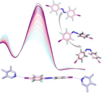
Fluorinated azobenzenes as supramolecular halogen-bonding building blocks
- Esther Nieland,
- Oliver Weingart and
- Bernd M. Schmidt
Beilstein J. Org. Chem. 2019, 15, 2013–2019, doi:10.3762/bjoc.15.197


Click chemistry towards thermally reversible photochromic 4,5-bisthiazolyl-1,2,3-triazoles
- Chenxia Zhang,
- Kaori Morinaka,
- Mahmut Kose,
- Takashi Ubukata and
- Yasushi Yokoyama
Beilstein J. Org. Chem. 2019, 15, 2161–2169, doi:10.3762/bjoc.15.213


Azologization and repurposing of a hetero-stilbene-based kinase inhibitor: towards the design of photoswitchable sirtuin inhibitors
- Christoph W. Grathwol,
- Nathalie Wössner,
- Sören Swyter,
- Adam C. Smith,
- Enrico Tapavicza,
- Robert K. Hofstetter,
- Anja Bodtke,
- Manfred Jung and
- Andreas Link
Beilstein J. Org. Chem. 2019, 15, 2170–2183, doi:10.3762/bjoc.15.214


Aggregation-induced emission effect on turn-off fluorescent switching of a photochromic diarylethene
- Luna Kono,
- Yuma Nakagawa,
- Ayako Fujimoto,
- Ryo Nishimura,
- Yohei Hattori,
- Toshiki Mutai,
- Nobuhiro Yasuda,
- Kenichi Koizumi,
- Satoshi Yokojima,
- Shinichiro Nakamura and
- Kingo Uchida
Beilstein J. Org. Chem. 2019, 15, 2204–2212, doi:10.3762/bjoc.15.217


Excited state dynamics for visible-light sensitization of a photochromic benzil-subsituted phenoxyl-imidazolyl radical complex
- Yoichi Kobayashi,
- Yukie Mamiya,
- Katsuya Mutoh,
- Hikaru Sotome,
- Masafumi Koga,
- Hiroshi Miyasaka and
- Jiro Abe
Beilstein J. Org. Chem. 2019, 15, 2369–2379, doi:10.3762/bjoc.15.229


Targeted photoswitchable imaging of intracellular glutathione by a photochromic glycosheet sensor
- Xianzhi Chai,
- Hai-Hao Han,
- Yi Zang,
- Jia Li,
- Xiao-Peng He,
- Junji Zhang and
- He Tian
Beilstein J. Org. Chem. 2019, 15, 2380–2389, doi:10.3762/bjoc.15.230


Reversible switching of arylazopyrazole within a metal–organic cage
- Anton I. Hanopolskyi,
- Soumen De,
- Michał J. Białek,
- Yael Diskin-Posner,
- Liat Avram,
- Moran Feller and
- Rafal Klajn
Beilstein J. Org. Chem. 2019, 15, 2398–2407, doi:10.3762/bjoc.15.232


![[Graphic 1]](/bjoc/content/inline/1860-5397-15-232-i3.svg?max-width=637&scale=1.18182) 2 (500 MHz, D2O, 298 K).
2 (500 MHz, D2O, 298 K).


Effect of ring size on photoisomerization properties of stiff stilbene macrocycles
- Sandra Olsson,
- Óscar Benito Pérez,
- Magnus Blom and
- Adolf Gogoll
Beilstein J. Org. Chem. 2019, 15, 2408–2418, doi:10.3762/bjoc.15.233


Photochromic diarylethene ligands featuring 2-(imidazol-2-yl)pyridine coordination site and their iron(II) complexes
- Andrey G. Lvov,
- Max Mörtel,
- Anton V. Yadykov,
- Frank W. Heinemann,
- Valerii Z. Shirinian and
- Marat M. Khusniyarov
Beilstein J. Org. Chem. 2019, 15, 2428–2437, doi:10.3762/bjoc.15.235


Ultrafast processes triggered by one- and two-photon excitation of a photochromic and luminescent hydrazone
- Alessandro Iagatti,
- Baihao Shao,
- Alberto Credi,
- Barbara Ventura,
- Ivan Aprahamian and
- Mariangela Di Donato
Beilstein J. Org. Chem. 2019, 15, 2438–2446, doi:10.3762/bjoc.15.236


Experimental and computational electrochemistry of quinazolinespirohexadienone molecular switches – differential electrochromic vs photochromic behavior
- Eric W. Webb,
- Jonathan P. Moerdyk,
- Kyndra B. Sluiter,
- Benjamin J. Pollock,
- Amy L. Speelman,
- Eugene J. Lynch,
- William F. Polik and
- Jason G. Gillmore
Beilstein J. Org. Chem. 2019, 15, 2473–2485, doi:10.3762/bjoc.15.240


In search of visible-light photoresponsive peptide nucleic acids (PNAs) for reversible control of DNA hybridization
- Lei Zhang,
- Greta Linden and
- Olalla Vázquez
Beilstein J. Org. Chem. 2019, 15, 2500–2508, doi:10.3762/bjoc.15.243


A toolbox of molecular photoswitches to modulate the CXCR3 chemokine receptor with light
- Xavier Gómez-Santacana,
- Sabrina M. de Munnik,
- Tamara A. M. Mocking,
- Niels J. Hauwert,
- Shanliang Sun,
- Prashanna Vijayachandran,
- Iwan J. P. de Esch,
- Henry F. Vischer,
- Maikel Wijtmans and
- Rob Leurs
Beilstein J. Org. Chem. 2019, 15, 2509–2523, doi:10.3762/bjoc.15.244


A photochemical determination of luminescence efficiency of upconverting nanoparticles
- Baptiste Amouroux,
- Clément Roux,
- Jean-Claude Micheau,
- Fabienne Gauffre and
- Christophe Coudret
Beilstein J. Org. Chem. 2019, 15, 2671–2677, doi:10.3762/bjoc.15.260


A combinatorial approach to improving the performance of azoarene photoswitches
- Joaquin Calbo,
- Aditya R. Thawani,
- Rosina S. L. Gibson,
- Andrew J. P. White and
- Matthew J. Fuchter
Beilstein J. Org. Chem. 2019, 15, 2753–2764, doi:10.3762/bjoc.15.266


A chiral self-sorting photoresponsive coordination cage based on overcrowded alkenes
- Constantin Stuckhardt,
- Diederik Roke,
- Wojciech Danowski,
- Edwin Otten,
- Sander J. Wezenberg and
- Ben L. Feringa
Beilstein J. Org. Chem. 2019, 15, 2767–2773, doi:10.3762/bjoc.15.268


Photoreversible stretching of a BAPTA chelator marshalling Ca2+-binding in aqueous media
- Aurélien Ducrot,
- Arnaud Tron,
- Robin Bofinger,
- Ingrid Sanz Beguer,
- Jean-Luc Pozzo and
- Nathan D. McClenaghan
Beilstein J. Org. Chem. 2019, 15, 2801–2811, doi:10.3762/bjoc.15.273


Chemical tuning of photoswitchable azobenzenes: a photopharmacological case study using nicotinic transmission
- Lorenzo Sansalone,
- Jun Zhao,
- Matthew T. Richers and
- Graham C. R. Ellis-Davies
Beilstein J. Org. Chem. 2019, 15, 2812–2821, doi:10.3762/bjoc.15.274


Design, synthesis and investigation of water-soluble hemi-indigo photoswitches for bioapplications
- Daria V. Berdnikova
Beilstein J. Org. Chem. 2019, 15, 2822–2829, doi:10.3762/bjoc.15.275


Synthesis and characterization of bis(4-amino-2-bromo-6-methoxy)azobenzene derivatives
- David Martínez-López,
- Amirhossein Babalhavaeji,
- Diego Sampedro and
- G. Andrew Woolley
Beilstein J. Org. Chem. 2019, 15, 3000–3008, doi:10.3762/bjoc.15.296


Light-controllable dithienylethene-modified cyclic peptides: photoswitching the in vivo toxicity in zebrafish embryos
- Sergii Afonin,
- Oleg Babii,
- Aline Reuter,
- Volker Middel,
- Masanari Takamiya,
- Uwe Strähle,
- Igor V. Komarov and
- Anne S. Ulrich
Beilstein J. Org. Chem. 2020, 16, 39–49, doi:10.3762/bjoc.16.6


Reversible photoswitching of the DNA-binding properties of styrylquinolizinium derivatives through photochromic [2 + 2] cycloaddition and cycloreversion
- Sarah Kölsch,
- Heiko Ihmels,
- Jochen Mattay,
- Norbert Sewald and
- Brian O. Patrick
Beilstein J. Org. Chem. 2020, 16, 111–124, doi:10.3762/bjoc.16.13


Potent hemithioindigo-based antimitotics photocontrol the microtubule cytoskeleton in cellulo
- Alexander Sailer,
- Franziska Ermer,
- Yvonne Kraus,
- Rebekkah Bingham,
- Ferdinand H. Lutter,
- Julia Ahlfeld and
- Oliver Thorn-Seshold
Beilstein J. Org. Chem. 2020, 16, 125–134, doi:10.3762/bjoc.16.14


