

Search results
Search for "dipeptide" in Full Text gives 92 result(s) in Beilstein Journal of Organic Chemistry.
Synthesis of heterocycles based on azomethine ylides from α-amino acids (or amines) and carbonyl compounds
- Ekaterina V. Berezhnaya,
- Alexander I. Ponyaev,
- Vitali M. Boitsov and
- Alexander V. Stepakov
Beilstein J. Org. Chem. 2026, 22, 705–741, doi:10.3762/bjoc.22.55

Graphical Abstract

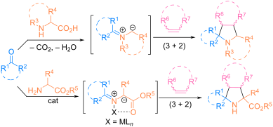
Scheme 1: Strategies for the preparation of pyrrolidine derivatives by (3 + 2) cycloaddition of azomethine yl...

Scheme 2: (3 + 2) Cycloaddition of iminoesters to dimethylmaleate.

Scheme 3: Cycloaddition of 1 with various dipolarophiles catalyzed by Ag(I)-L1.

Scheme 4: Cycloaddition of 1 with tert-butyl acrylate catalyzed by Ag(I)-L2.

Scheme 5: Cycloaddition of 1 with dimethyl maleate catalyzed by Cu(I)-L3.

Scheme 6: Cycloaddition of 1 with alkenes catalyzed by Zn(II)-t-Bu-BOX (L4).

Scheme 7: (3 + 2) Cycloaddition of iminoesters to acrylates.

Scheme 8: Catalytic double (3 + 2) cycloaddition to form pyrrolizidine derivatives.

Scheme 9: (3 + 2) Cycloaddition of iminoethers to vinyl phenyl sulfone.

Scheme 10: Regiodivergent and enantioselective synthesis of pyrrolidines 16 and 17.

Scheme 11: Substrate-controlled regioreversible "normal" and "incomplete" 1,3-dipolar cycloaddition.

Scheme 12: Enantioselective synthesis of exo-/endo-pyrrolidines.

Scheme 13: (3 + 2) Cycloaddition of iminoethers 21 to dipolarophiles 22–24.

Scheme 14: Synthesis of bicyclic pyrrolidines 29 from cyclopentene-1,3-diones.

Scheme 15: (3 + 2) Cycloaddition of aldimine esters and allyl alcohols using copper-ruthenium catalysis.

Scheme 16: Synthesis of 3,3-difluoro- and 3,3,4-trifluoropyrrolidine derivatives.

Scheme 17: Use of iminoesters from natural compounds and pharmaceuticals for reactions with 1,1-difluoro- and ...

Scheme 18: Reaction of iminoesters with 1,3-enynes.

Scheme 19: Synthesis of pyrrolidines from iminoesters and vinyl(hetero)arenes.

Scheme 20: Synthesis of exo-pyrrolidines 42 and 43.

Scheme 21: Enantioselective synthesis of heteroarylpyrrolidines 45 and 46.

Scheme 22: Catalytic reaction of (3 + 2) cycloaddition of imines 12 to benzofulvenes 47.

Scheme 23: Fullerene as a dipolarophile in (3 + 2) cycloaddition reactions.

Scheme 24: Asymmetric synthesis of optically active tetrasubstituted pyrrolidines 54.

Scheme 25: (3 + 2) Cycloaddition reaction of imines 55 and α,β-unsaturated aldehydes.

Scheme 26: Probable mechanism of enantioselective (3 + 2) cycloaddition of azomethine ylides to α,β-unsaturate...

Scheme 27: Cycloaddition between iminoesters 12 and sulfinylimines 58.

Scheme 28: (3 + 2) Cycloaddition between triarylideneacetylacetone and azomethine ylides in the presence of ti...

Scheme 29: Stereoselective synthesis of decahydropyrrolo[2,1,5-cd]indolizine 66.

Scheme 30: Synthesis of policyclic derivatives 71 and 72.

Scheme 31: Catalytic аsymmetric (3 + 2) сycloaddition of 2-pyridylimines with N-methylmaleimide.

Scheme 32: Catalytic аsymmetric (3 + 2) сycloaddition of 2-pyridylimines 1 with other dipolarophiles.

Scheme 33: Enantioselective (3 + 2) cycloaddition of silylimine with various dipolarophiles.

Scheme 34: Proposed mechanism of formation of pyrrolidines 78.

Scheme 35: Synthesis of polyheterocyclic pyrrolidines 82–91.

Scheme 36: Synthesis of spirocyclic (95) and fused (96) pyrrolidines.

Scheme 37: (3 + 2) Cycloaddition involving aromatic aldehydes 97, N-propargylmaleimide (98) and α-amino acids ...

Scheme 38: Synthesis of pyrrolizidines 106 and by-product 107.

Scheme 39: Iridium-catalyzed three-component cascade (3 + 2) cycloaddition.

Scheme 40: Intramolecular (3 + 2) cycloaddition of N-alkenylpyrrole-2-carbaldehyde 110 and α-amino acids.

Scheme 41: Three-component (3 + 2) cycloaddition involving fullerene.

Scheme 42: Four-component stereoselective one-pot synthesis of spiro-cycloadducts 119–122.

Scheme 43: Reactions of azomethine ylide 123 with cyclopropenes.

Scheme 44: Three-component reactions involving ninhydrin, cyclopropenes and acyclic α-amino acids.

Scheme 45: Reaction of cyclopropenes 138 with the N-protonated form of Ruhemann purple 137.

Scheme 46: Enantioselective (3 + 2) cycloaddition of azomethine ylides generated in situ from isatins and amin...

Scheme 47: (3 + 2) Cycloaddition of cyclohexenone 143, isatins 140 and aminomalonic diesters 141, catalyzed by...

Scheme 48: Enantioselective (3 + 2) cycloaddition of azomethine ylides generated in situ from isatins and amin...

Scheme 49: Enantioselective (3 + 2) cycloaddition of azomethine ylides generated in situ from isatins and benz...

Scheme 50: (3 + 2) Cycloaddition involving isatins, azetidine-2-carboxylic acid, maleimides or itaconimides.

Scheme 51: (3 + 2) Cycloaddition involving isatins, amino acids and tetraethylvinylidenebis(phosphonate).

Scheme 52: Synthesis of spirooxindoles 156 from triarylideneacetylacetones 155.

Scheme 53: Synthesis of spirooxindole derivatives 157–160.

Scheme 54: Synthesis of hybrid spiro-heterocycles 164–166.

Scheme 55: Formation of azomethine ylide from isatin and sarcosine.

Scheme 56: (3 + 2) Cycloaddition involving isatins, amino acids and trans-3-benzoylacrylic acid.

Scheme 57: Regioselective synthesis of spirooxindoles 170.

Scheme 58: Synthesis of hybrid spiro-heterocycles 86.

Scheme 59: (3 + 2) Cycloaddition involving acenaphthenequinones, amino acids and cyclopropenes.

Scheme 60: Synthesis of hybrid glyco-3-nitrochromane cycloadducts 179.

Scheme 61: Synthesis of spiro[indenoquinoxaline-(thia)pyrrolizidines] 90a.

Scheme 62: Three-component reactions of cyclopropenes, 11H-indeno[1,2-b]quinoxalin-11-onesand α-amino acids, s...

Scheme 63: Synthesis of hybrid glyco-3-nitrochromane cycloadducts 92.

Scheme 64: (3 + 2) Cycloaddition of 11H-benzo[4,5]imidazo[1,2-a]indol-11-one (189) with cyclopropenes and male...

Scheme 65: Diastereoselective synthesis of spiro derivatives of barbituric acid from alloxan 193, α-amino acid...

Scheme 66: Probable mechanism of formation of azomethine ylide from alloxan and ʟ-proline.

Scheme 67: Three-component reactions involving tryptanthrin 196, α-amino acids and cyclopropenes.
Recent advances in the cleavage of non-activated amides
- Eun-Sol Choi and
- Hyo-Jun Lee
Beilstein J. Org. Chem. 2026, 22, 352–369, doi:10.3762/bjoc.22.23
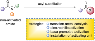
- then decomposes to furnish the acyl fluorides 194. This strategy provided chemoselective peptide modification. For example, the amide bond possessing the PMB unit in dipeptide 209 (N-Phth-ʟ-Ala-N-PMB-ʟ-Ala-OMe) was selectively activated and cleaved, generating the corresponding acyl fluoride

Graphical Abstract
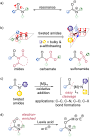
Scheme 1: a) Resonance structure of amide. b) Concept of twisted amides. c) Transition-metal-catalyzed activa...
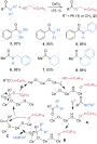
Scheme 2: Esterification of amides catalyzed by CeO2.

Scheme 3: Hydrolysis of amides catalyzed by Nb2O5.
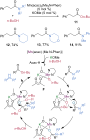
Scheme 4: Manganese-catalyzed esterification of tertiary amides.
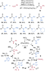
Scheme 5: Tungsten-catalyzed transamidation of hindered tertiary amides.
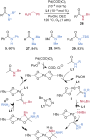
Scheme 6: Palladium-catalyzed transamidation of amides.

Scheme 7: Synthesis of benzyl esters via electrophilic activation of amides using DPT-BM.

Scheme 8: Esterification of amides promoted by SO2F2.
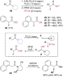
Scheme 9: α-Fluorinative cleavage of pyrrolidine-based tertiary amides via double electrophilic activation wi...
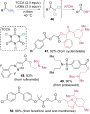
Scheme 10: Esterification of primary amides using TCCA via the generation of RCONCl2.
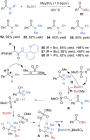
Scheme 11: Esterification of amides via electrophilic activation with Me2SO4.
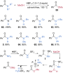
Scheme 12: HBF4-mediated esterification of amides.
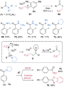
Scheme 13: Synthesis of 2,2,2-trifluoroethyl esters via electrophilic esterification of amide promoted by 67.
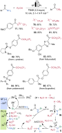
Scheme 14: Electrochemical activation of C–N bonds for esterification.

Scheme 15: Catalyst- and reagent-free transamidation of amide using aniline hydrochloride salt.
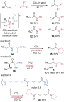
Scheme 16: CO2-catalyzed transamidation of amides.
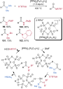
Scheme 17: Transamidation of formamides using cyclic dihydrogen tetrametaphosphate.

Scheme 18: BF3·OEt2-mediated transamidation of primary amides.

Scheme 19: Acyl iodide intermediate 121 generation from amides for the transamidation using HOTf and KI.
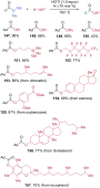
Scheme 20: Esterification of N,N-dimethyl amides via electrophilic generation of acyl iodide intermediates.

Scheme 21: Transamidation of DMAc promoted by KOt-Bu.
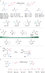
Scheme 22: a) LiHMDS-mediated transamidation of tertiary amides. b) Computed reactivities of selected amides. ...

Scheme 23: Zn-catalyzed chemoselective cleavage of amides directed by tert-butyl nicotinate.

Scheme 24: Chemoselective cleavage of N-PMB anilide for transamidation via acyl fluoride 194 generation. a) Cu...
Synthesis and applications of alkenyl chlorides (vinyl chlorides): a review
- Daniel S. Müller
Beilstein J. Org. Chem. 2026, 22, 1–63, doi:10.3762/bjoc.22.1
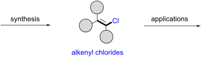
- exploited in the preparation of peptidomimetics incorporating chloroalkene dipeptide isosteres [206]. 1.11 Miscellaneous reactions In 2014, Du and Zhao reported that PhICl2 in wet DMF was found transform alkenes regioselectively into the corresponding chloroformyloxylated products or α-chlorinated olefinic

Graphical Abstract
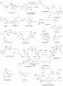
Figure 1: Representative alkenyl chloride motifs in natural products. References: Pinnaic acid [8], haterumalide ...

Figure 2: Representative alkenyl chloride motifs in pharmaceuticals and pesticides. References: clomifene [25], e...
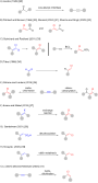
Figure 3: Graphical overview of previously published reviews addressing the synthesis of alkenyl chlorides.

Figure 4: Classification of synthetic approaches to alkenyl chlorides.

Scheme 1: Early works by Friedel, Henry, and Favorsky.

Scheme 2: Product distribution obtained by H NMR integration of crude compound as observed by Kagan and co-wo...

Scheme 3: Side reactions observed for the reaction of 14 with PCl5.

Scheme 4: Only compounds 15 and 18 were observed in the presence of Hünig’s base.

Scheme 5: Efficient synthesis of dichloride 15 at low temperatures.
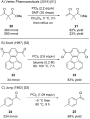
Scheme 6: Various syntheses of alkenyl chlorides on larger scale.

Scheme 7: Scope of the reaction of ketones with PCl5 in boiling cyclohexane.

Scheme 8: Side reactions occur when using excess amounts of PCl5.

Scheme 9: Formation of versatile β-chlorovinyl ketones.

Scheme 10: Mixture of PCl5 and PCl3 used for the synthesis of 49.

Scheme 11: Catechol–PCl3 reagents for the synthesis of alkenyl chlorides.

Scheme 12: (PhO)3P–halogen-based reagents for the synthesis of alkenyl halides.

Scheme 13: Preparation of alkenyl chlorides from alkenyl phosphates.

Scheme 14: Preparation of alkenyl chlorides by treatment of ketones with the Vilsmeier reagent.

Scheme 15: Preparation of electron-rich alkenyl chlorides by treatment of ketones with the Vilsmeier reagent.

Scheme 16: Cu-promoted synthesis of alkenyl chlorides from ketones and POCl3.

Figure 5: GC yield of 9 depending on time and reaction temperature.

Figure 6: Broken reaction flask after attempts to clean the polymerized residue.

Figure 7: GC yield of 9 depending on the amount of CuCl and time.

Scheme 17: Treatment of 4-chromanones with PCl3.

Scheme 18: Synthesis of alkenyl chlorides from the reaction of ketones with acyl chlorides.

Scheme 19: ZnCl2-promoted alkenyl chloride synthesis.
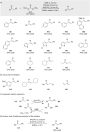
Scheme 20: Regeneration of acid chlorides by triphosgene.

Scheme 21: Alkenyl chlorides from ketones and triphosgene.
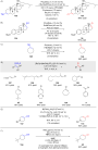
Scheme 22: Various substitution reactions.

Scheme 23: Vinylic Finkelstein reactions reported by Evano and co-workers.

Scheme 24: Challenge of selective monohydrochlorination of alkynes.

Scheme 25: Sterically encumbered internal alkynes furnish the hydrochlorination products in high yield.

Scheme 26: Recent work by Kropp with HCl absorbed on alumina.

Scheme 27: High selectivities for monhydrochlorination with nitromethane/acetic acid as solvent.

Figure 8: Functionalized alkynes which typically afford the monhydrochlorinated products.
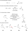
Scheme 28: Related chorosulfonylation and chloroamination reactions.
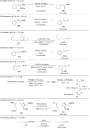
Scheme 29: Reaction of organometallic reagents with chlorine electrophiles.

Scheme 30: Elimination reactions of dichlorides to furnish alkenyl chlorides.

Scheme 31: Elimination reactions of allyl chloride 182 to furnish alkenyl chloride 183.

Scheme 32: Detailed studies by Schlosser on the elimination of dichloro compounds.

Scheme 33: Stereoselective variation caused by change of solvent.

Scheme 34: Elimination of gem-dichloride 189 to afford alkene 190.

Scheme 35: Oxidation of enones to dichlorides and in situ elimination thereof.

Scheme 36: Oxidation of allylic alcohols to dichlorides and in situ elimination thereof.

Scheme 37: Chlorination of styrenes with SOCl2 and elimination thereof.

Scheme 38: Chlorination of styrenes with SOCl2 and elimination thereof.

Scheme 39: Fluorine–chlorine exchange followed by elimination.

Scheme 40: Intercepting cations with alkynes and trapping of the alkenyl cation intermediate with chloride.

Scheme 41: Investigations by Mayr and co-workers.

Scheme 42: In situ activation of benzyl alcohol 230 with BCl3.

Scheme 43: In situ activation of benzylic alcohols with TiCl4.
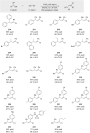
Scheme 44: In situ activation of benzylic alcohols with FeCl3.

Scheme 45: In situ activation of benzylic alcohols with FeCl3.

Scheme 46: In situ activation of aliphatic chlorides and alcohols with ZnCl2, InCl3, and FeCl3.

Scheme 47: In situ generation of benzylic cations and trapping thereof with alkynes.
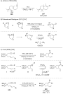
Scheme 48: Intramolecular trapping reactions affording alkenyl halides.

Scheme 49: Intramolecular trapping reactions affording alkenyl chlorides.

Scheme 50: Intramolecular trapping reactions of oxonium and iminium ions affording alkenyl chlorides.
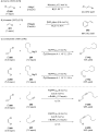
Scheme 51: Palladium and nickel-catalyzed coupling reactions to afford alkenyl chlorides.

Scheme 52: Rhodium-catalyzed couplings of 1,2-trans-dichloroethene with arylboronic esters.

Scheme 53: First report on monoselective coupling reactions for 1,1-dichloroalkenes.

Scheme 54: Negishi’s and Barluenga’s contributions.

Scheme 55: First mechanistic investigation by Johnson and co-workers.

Scheme 56: First successful cross-metathesis with choroalkene 260.

Scheme 57: Subsequent studies by Johnson.
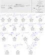
Scheme 58: Hoveyda and Schrock’s work on stereoretentive cross-metathesis with molybdenum-based catalysts.
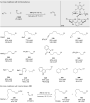
Scheme 59: Related work with (Z)-dichloroethene.
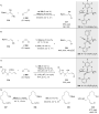
Scheme 60: Further ligand refinement and traceless protection of functional groups with HBpin.

Scheme 61: Alkenyl chloride synthesis by Wittig reaction.

Scheme 62: Alkenyl chloride synthesis by Julia olefination.

Scheme 63: Alkenyl chloride synthesis by reaction of ketones with Mg/TiCl4 mixture.

Scheme 64: Frequently used allylic substitution reactions which lead to alkenyl chlorides.
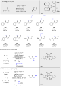
Scheme 65: Enantioselective allylic substitutions.

Scheme 66: Synthesis of alkenyl chlorides bearing an electron-withdrawing group.

Scheme 67: Synthesis of α-nitroalkenyl chlorides from aldehydes.

Scheme 68: Synthesis of alkenyl chlorides via elimination of an in situ generated geminal dihalide.

Scheme 69: Carbenoid approach reported by Pace.

Scheme 70: Carbenoid approach reported by Pace.

Scheme 71: Ring opening of cyclopropenes in the presence of MgCl2.

Scheme 72: Electrophilic chlorination of alkenyl MIDA boronates to Z- or E-alkenyl chlorides.

Scheme 73: Hydroalumination and hydroboration of alkynyl chlorides.

Scheme 74: Carbolithiation of chloroalkynes.

Scheme 75: Chlorination of enamine 420.

Scheme 76: Alkyne synthesis by elimination of alkenyl chlorides.

Scheme 77: Reductive lithiation of akenyl chlorides.

Scheme 78: Reactions of alkenyl chlorides with organolithium reagents.

Scheme 79: Reactions of alkenyl chlorides with organolithium reagents.

Scheme 80: Addition–elimination reaction of alkenyl chloride 9 with organolithium reagents.

Scheme 81: C–H insertions of lithiumcarbenoids.
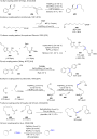
Scheme 82: Pd-catalyzed coupling reactions with alkenyl chlorides as coupling partner.

Scheme 83: Ni-catalyzed coupling of alkenylcopper reagent with alkenyl chloride 183.

Scheme 84: Ni-catalyzed coupling of heterocycle 472 with alkenyl chloride 473.

Scheme 85: Synthesis of α-chloroketones by oxidation of alkenyl chlorides.

Scheme 86: Tetrahalogenoferrate(III)-promoted oxidation of alkenyl chlorides.

Scheme 87: Chlorine–deuterium exchange promoted by a palladium catalyst.

Scheme 88: Reaction of alkenyl chlorides with thiols in the presence of AIBN (azobisisobutyronitrile).

Scheme 89: Chloroalkene annulation.
Total synthesis of asperdinones B, C, D, E and terezine D
- Ravi Devarajappa and
- Stephen Hanessian
Beilstein J. Org. Chem. 2025, 21, 2730–2738, doi:10.3762/bjoc.21.210
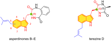
- metabolite and cyclic dipeptide consisting of a 7-prenylated ʟ-tryptophan and ʟ-alanine was isolated from the liquid cultures of S. teretispora containing potato broth in the medium. Its structure was based on extensive spectroscopic studies (Figure 1). Terezine D (6) exhibited modest in vitro antifungal

Graphical Abstract

Figure 1: Structures of prenylindole alkaloids derived from tryptophan.

Figure 2: Representative retrosynthetic considerations for 7-prenyl- and 7-allyltryptophan.

Scheme 1: C-7 Functionalization of 7-iodo-Nα-Boc-tryptophan methyl ester.

Scheme 2: C-7 Prenylation via C–H activation.

Figure 3: Negishi cross-coupling of allyl- and prenyl(iodo)indoles.

Scheme 3: Synthesis of prenyl- and allylindoles.

Scheme 4: Markovnikov hydrochlorination and hydrotrifluoroacetylation.

Scheme 5: Synthesis of asperdinones B–E 1–4.

Scheme 6: Control experiment.

Scheme 7: Control experiment of the Negishi cross-coupling reaction.

Scheme 8: Synthesis of terezine D and ent-asperdinone E.
Electrochemical cyclization of alkynes to construct five-membered nitrogen-heterocyclic rings
- Lifen Peng,
- Ting Wang,
- Zhiwen Yuan,
- Bin Li,
- Zilong Tang,
- Xirong Liu,
- Hui Li,
- Guofang Jiang,
- Chunling Zeng,
- Henry N. C. Wong and
- Xiao-Shui Peng
Beilstein J. Org. Chem. 2025, 21, 2173–2201, doi:10.3762/bjoc.21.166
- in 66%–87% yields. Boc-amino ester (2e), dipeptide (2f), apivalate ester (2g) and ethinyl estradiol (2h) skeletons were also tolerated well. According to the previous works [163] and the experimental results, the authors proposed a plausible mechanism. Firstly, the anodic oxidation of [Cp2Fe

Graphical Abstract

Figure 1: Natural products and functional molecules possessing five-membered rings.

Scheme 1: Electrochemical intramolecular coupling of ureas to form indoles.
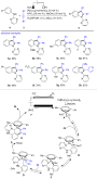
Scheme 2: Electrochemical dehydrogenative annulation of alkynes with anilines.

Scheme 3: Electrochemical annulations of o-arylalkynylanilines.
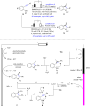
Scheme 4: Electrochemical cyclization of 2-ethynylanilines.
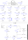
Scheme 5: Electrochemical selenocyclization of diselenides and 2-ethynylanilines.

Scheme 6: Electrochemical cascade approach towards 3-selenylindoles.

Scheme 7: Electrochemical C–H indolization.

Scheme 8: Electrochemical annulation of benzamides and terminal alkynes.

Scheme 9: Electrochemical synthesis of isoindolinone by 5-exo-dig aza-cyclization.

Scheme 10: Electrochemical reductive cascade annulation of o-alkynylbenzamide.

Scheme 11: Electrochemical intramolecular 1,2-amino oxygenation of alkyne.
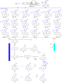
Scheme 12: Electrochemical multicomponent reaction of nitrile, (thio)xanthene, terminal alkyne and water.

Scheme 13: Electrochemical aminotrifluoromethylation/cyclization of alkynes.

Scheme 14: Electrochemical cyclization of o-nitrophenylacetylene.
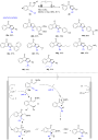
Scheme 15: Electrochemical annulation of alkynyl enaminones.

Scheme 16: Electrochemical annulation of alkyne and enamide.

Scheme 17: Electrochemical tandem Michael addition/azidation/cyclization.

Scheme 18: Electrochemical [3 + 2] cyclization of heteroarylamines.

Scheme 19: Electrochemical CuAAC to access 1,2,3-triazole.
Silver(I) triflate-catalyzed post-Ugi synthesis of pyrazolodiazepines
- Muhammad Hasan,
- Anatoly A. Peshkov,
- Syed Anis Ali Shah,
- Andrey Belyaev,
- Chang-Keun Lim,
- Shunyi Wang and
- Vsevolod A. Peshkov
Beilstein J. Org. Chem. 2025, 21, 915–925, doi:10.3762/bjoc.21.74
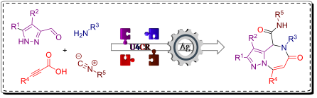
- [20][21][22][23]. For example, the Ugi four-component reaction (U4CR), involving a carbonyl compound, a primary amine, a carboxylic acid, and an isocyanide, provides a straightforward method for constructing dipeptide-like adducts [24][25][26][27]. These adducts can subsequently be rigidified into

Graphical Abstract

Figure 1: Representative diazepine-fused heterocycles.

Scheme 1: Post-Ugi synthesis of benzodiazepines and heteroaryl-fused diazepines.

Scheme 2: Synthesis of pyrazole-tethered propargylamides 15 via U4CR. Conditions: Unless otherwise specified,...
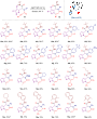
Scheme 3: Scope of the silver(I) triflate-catalyzed synthesis of pyrazolo[1,5-a][1,4]diazepines. Conditions: ...

Scheme 4: Telescope procedure for the synthesis of 16a.

Scheme 5: Tentative mechanism for the silver-catalyzed heteroannulation.

Scheme 6: Reductive post-assembly modifications of the pyrazolo[1,5-a][1,4]diazepine core. aDetermined by 1H ...
Entry to 2-aminoprolines via electrochemical decarboxylative amidation of N‑acetylamino malonic acid monoesters
- Olesja Koleda,
- Janis Sadauskis,
- Darja Antonenko,
- Edvards Janis Treijs,
- Raivis Davis Steberis and
- Edgars Suna
Beilstein J. Org. Chem. 2025, 21, 630–638, doi:10.3762/bjoc.21.50
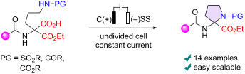
- the scalability of the method, and 470 mg of 2-aminoproline derivative 6j was obtained in a single electrolysis batch. The wide application of unnatural amino acids in the design of peptidomimetics prompted us to examine the suitability of the developed conditions for dipeptide synthesis. Gratifyingly
- 13a,d,e in 71–83% yield (Scheme 4). Carboxylic acid 13a could be reacted with glycine benzyl ester in the presence of HATU and Et3N to form dipeptide 16 (66%). In contrast, N-unprotected 2-aminoprolines are unstable and could not be isolated. Thus, the cleavage of the N-Cbz protecting group in 6b
- ester moiety with LiBH4. In the meantime, the hydrogenolysis of the benzyl ester in dipeptide 16 proceeded smoothly and afforded carboxylic acid 17 in 81% yield (Scheme 4) [16]. Conclusion In summary, the developed electrochemical decarboxylative amidation of readily accessible malonic acid monoesters

Graphical Abstract
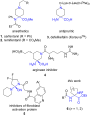
Figure 1: Selected examples of α,α-disubstituted cyclic amino acids in drug design.

Figure 2: Electrochemical decarboxylative amination reactions.

Scheme 1: Preparation of malonic acid monoester 9a.

Figure 3: A) Cyclic voltammograms of 6a and 9a at 3 mM and 6 mM concentration, respectively, in 5:1 MeCN/H2O ...

Scheme 2: Electrolysis of acid 9d in deuterated solvents.

Figure 4: Plausible mechanism for formation of pyrrolidine 6a and hemiaminal 10a.

Scheme 3: Scope of the decarboxylative amidation. aStainless-steel cathode; bgraphite cathode; cyield determi...

Scheme 4: Synthetic modifications of 2-aminoproline derivatives 6.
Synthesis of tricarbonylated propargylamine and conversion to 2,5-disubstituted oxazole-4-carboxylates
- Kento Iwai,
- Akari Hikasa,
- Kotaro Yoshioka,
- Shinki Tani,
- Kazuto Umezu and
- Nagatoshi Nishiwaki
Beilstein J. Org. Chem. 2024, 20, 2827–2833, doi:10.3762/bjoc.20.238

- ] because of their easily modifiable dipeptide frameworks. Several methods exist for accessing PCPAs, such as the amination of 1-halo-1-alkynes [16][17], tandem reactions of α-imino esters with nucleophiles and electrophiles [18], and the nucleophilic addition of an acetylide to α-carbonylated N-acylimines

Graphical Abstract

Scheme 1: Synthesis of polyfunctionalized methane derivatives through successive nucleophilic additions to th...

Scheme 2: Cyclization of 4a quenched by D2O.

Scheme 3: Plausible mechanisms for the ring closure of 4.

Scheme 4: Hydration of the ethynyl group of 4a.
Direct synthesis of acyl fluorides from carboxylic acids using benzothiazolium reagents
- Lilian M. Maas,
- Alex Haswell,
- Rory Hughes and
- Matthew N. Hopkinson
Beilstein J. Org. Chem. 2024, 20, 921–930, doi:10.3762/bjoc.20.82
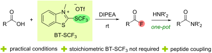
- , replacing the benzylamine coupling partner with phenylalanine methyl ester provided dipeptide 5t in 67% yield (Scheme 3b). With the scope of the deoxyfluorination process established, our attention turned to an investigation of the reaction mechanism (Scheme 4). As demonstrated in our previous work

Graphical Abstract

Figure 1: Advantages of acyl fluorides compared to acyl chlorides, previous work on BT-SRF reagents [29-33] and a su...

Scheme 1: Scope of the BT-SCF3-mediated deoxygenative fluorination of carboxylic acids 1. Reactions were perf...
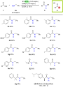
Scheme 2: Scope of the one-pot BT-SCF3-mediated deoxygenative coupling of carboxylic acids and amines via acy...

Scheme 3: One-pot BT-SCF3-mediated deoxygenative coupling of amino acids. Isolated yields after column chroma...
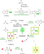
Scheme 4: Plausible mechanism for the deoxyfluorination of carboxylic acids with BT-SCF3.
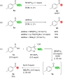
Scheme 5: Mechanistic experiments. (a) Conversion of thioester 3a into acyl fluoride 2a in the presence of DI...
Synthesis of ether lipids: natural compounds and analogues
- Marco Antônio G. B. Gomes,
- Alicia Bauduin,
- Chloé Le Roux,
- Romain Fouinneteau,
- Wilfried Berthe,
- Mathieu Berchel,
- Hélène Couthon and
- Paul-Alain Jaffrès
Beilstein J. Org. Chem. 2023, 19, 1299–1369, doi:10.3762/bjoc.19.96

Graphical Abstract

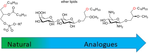
Figure 1: Chemical structure of some natural ether lipids (ELs).

Figure 2: Synthesis of lyso-PAF and PAF from 1-O-alkylglycerol [64].

Figure 3: Synthesis of lyso-PAF from 1,3-benzylideneglycerol 3.1 [69].
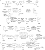
Figure 4: A) Synthesis of the two enantiomers of octadecylglycerol (4.6 and 4.10) from ᴅ-mannitol (4.1); B) s...

Figure 5: Four-step synthesis of PAF 5.6 from (S)-glycidol [73].

Figure 6: Synthesis of 1-O-alkylglycerol A) from solketal, B) from ᴅ- or ʟ-tartaric acid and the intermediate ...

Figure 7: Synthesis of EL building blocks starting from substituted glycidol 7.1a–c [82].

Figure 8: Synthesis of PAF 8.5 by using phosphoramidite 8.2 [86].

Figure 9: Synthesis of oleyl-PAF 9.7 from ʟ-serine [88].

Figure 10: Synthesis of racemic analogues of lyso-PAF 10.8 and PAF 10.9 featuring a phenyl group between the g...

Figure 11: Synthesis of racemic deoxy-lyso-PAF 11.7 and deoxy-PAF 11.8 [91].

Figure 12: Synthesis of racemic thio-PAF 12.8 [93].

Figure 13: Racemic synthesis of 13.6 to illustrate the modification of the glycerol backbone by adding a methy...

Figure 14: Racemic synthesis of 14.5 as an illustration of the introduction of methyl substituents on the glyc...

Figure 15: Synthesis of functionalized sn-2-acyl chains of PC-EL; A) Steglich esterification or acylation reac...

Figure 16: Synthesis of racemic mc-PAF (16.3), a carbamate analogue of PAF [102].

Figure 17: A) Synthesis of (R)-17.2 and (S)-17.6 starting from (S)-solketal (17.1); B) synthesis of N3-PAF (17...

Figure 18: Modification of the phosphocholine polar head to produce PAF analogues [81].

Figure 19: Racemic PAF analogues 19.3 and 19.5 characterized by the absence of the phosphate group [107].

Figure 20: Synthesis of PIP3-PAF (20.7) [108].

Figure 21: Large-scale synthesis of C18-edelfosine (21.8) [116].

Figure 22: Synthesis of C16-edelfosine (22.10) starting from isopropylidene-ʟ-glyceric acid methyl ester (22.1...

Figure 23: Phosphocholine moiety installation by the use of chlorophosphite 23.2 as key reagent [119].

Figure 24: Synthesis of rac-1-alkyl-2-O-methylglycerol (AMG) [120].

Figure 25: Synthesis of stereocontrolled 1-alkyl-2-O-methyl glycerol 25.9 (AMG) from dimethyl ᴅ-tartrate [81].

Figure 26: A) Racemic synthesis of thioether 26.4 [129,130], B) structure of sulfone analogue 26.5 [129].

Figure 27: Stereocontrolled synthesis of C18-edelfosine thioether analogue 27.8 [118].

Figure 28: Synthesis of thioether 28.4 that include a thiophosphate function [134].

Figure 29: Synthesis of ammonium thioether 29.4 and 29.6 [135].

Figure 30: Synthesis of the N-methylamino analogue of edelfosine 30.6 (BN52211) [138].

Figure 31: Synthesis of 1-desoxy analogues of edelfosine; A) with a saturated alkyl chain; B) synthesis of the...

Figure 32: Stereocontrolled synthesis of edelfosine analogue (S)-32.8 featuring a C18:1 lipid chain [142].

Figure 33: Synthesis of edelfosine analogues with modulation of the lipid chain; A) illustration with the synt...

Figure 34: Synthesis of phospholipid featuring a carbamate function to link the lipid chain to the glycerol un...

Figure 35: Synthesis of sesquiterpene conjugates of phospho glycero ether lipids [148].

Figure 36: Racemic synthesis of methyl-substituted glycerol analogues 36.7 and 36.10: A) synthesis of diether ...

Figure 37: Racemic synthesis of ilmofosine (37.6) [155,156].

Figure 38: A) Stereoselective synthesis of 38.5 via a stereoselective hydroboration reaction; B) synthesis of ...

Figure 39: Racemic synthesis of SRI62-834 (39.6) featuring a spiro-tetrahydrofurane heterocycle in position 2 ...

Figure 40: Racemic synthesis of edelfosine analogue 40.5 featuring an imidazole moiety in sn-2 position [160].

Figure 41: Racemic synthesis of fluorine-functionalized EL: A) Synthesis of 41.6 and B) synthesis of 41.8 [161-163].

Figure 42: A) Synthesis of the β-keto-ester 42.6 that also features a decyl linker between the phosphate and t...

Figure 43: Synthesis of phosphonate-based ether lipids; A) edelfosine phosphonate analogue 43.7 and B) thioeth...

Figure 44: Enantioselective synthesis of phosphonates 44.3 and 44.4 [171].

Figure 45: Racemic synthesis of phosphinate-based ether lipid 45.10 [172].

Figure 46: Racemic synthesis of edelfosine arsonium analogue 46.5 [173].

Figure 47: Synthesis of edelfosine dimethylammonium analogue 47.2 [118].

Figure 48: Synthesis of rac-C18-edelfosine methylammonium analogue 48.4 [176].

Figure 49: A) Synthesis of edelfosine N-methylpyrrolidinium analogue 49.2 or N-methylmorpholinium analogue 49.3...

Figure 50: A) Synthesis of edelfosine’s analogue 50.4 with a PE polar group; B) illustration of a pyridinium d...

Figure 51: A) Synthesis of 51.4 featuring a thiazolium cationic moiety; B) synthesis of thiazolium-based EL 51...

Figure 52: Synthesis of cationic ether lipids 52.3, 52.4 and 52.6 [135,183].

Figure 53: Synthesis of cationic carbamate ether lipid 53.5 [184].

Figure 54: Synthesis of cationic sulfonamide 54.5 [185].

Figure 55: Chemical structure of ONO-6240 (55.1) and SRI-63-119 (55.2).

Figure 56: Synthesis of non-ionic ether lipids 56.2–56.9 [188].

Figure 57: Synthesis of ether lipid conjugated to foscarnet 57.6 [189].

Figure 58: A) Synthesis of ether lipid conjugated to arabinofuranosylcytosine; B) synthesis of AZT conjugated ...

Figure 59: Synthesis of quercetin conjugate to edelfosine [191].

Figure 60: Synthesis of 60.8 (Glc-PAF) [194].

Figure 61: A) Synthesis of amino ether lipid 61.7 functionalized with a rhamnose unit and its amide analogue 6...

Figure 62: A) Synthesis of glucose ether lipid 62.4; B) structure of ether lipid 62.5 possessing a maltose uni...

Figure 63: A) Synthesis of glucuronic methyl ester 63.8; B) structure of cellobiose 63.9 and maltose 63.10 ana...

Figure 64: A) Synthesis of maltosyl glycerolipid 64.7; B) structure of lactose analogue 64.8 prepared followin...

Figure 65: A) Asymmetric synthesis of the aglycone moiety starting from allyl 4-methoxyphenyl ether; B) glycos...

Figure 66: A) Synthesis of ohmline possessing a lactose moiety. B) Structure of other glyco glycero lipids pre...

Figure 67: A) Synthesis of lactose-glycerol ether lipid 67.5; B) analogues possessing a maltose (67.6) or meli...

Figure 68: Synthesis of digalactosyl EL 68.6, A) by using trityl, benzyl and acetyl protecting groups, B) by u...

Figure 69: A) Synthesis of α-ohmline; B) structure of disaccharide ether lipids prepared by using similar meth...

Figure 70: Synthesis of lactose ether lipid 70.3 and its analogue 70.6 featuring a carbamate function as linke...

Figure 71: Synthesis of rhamnopyranoside diether 71.4 [196].

Figure 72: Synthesis of 1-O-hexadecyl-2-O-methyl-3-S-(α-ᴅ-1'-thioglucopyranosyl)-sn-glycerol (72.5) [225].

Figure 73: A) Preparation of lipid intermediate 73.4; B) synthesis of 2-desoxy-C-glycoside 73.10 [226].

Figure 74: Synthesis of galactose-pyridinium salt 74.3 [228].

Figure 75: Synthesis of myo-inositol derivative Ino-C2-PAF (75.10) [230].

Figure 76: A) Synthesis of myo-inositol phosphate building block 76.7; B) synthesis of myo-inositolphosphate d...

Figure 77: A) Synthesis of phosphatidyl-3-desoxy-inositol 77.4; B) synthesis of phosphono-3-desoxyinositol 77.9...

Figure 78: A) Structure of diether phosphatidyl-myo-inositol-3,4-diphosphate 78.1; B) synthesis of phosphatidy...

Figure 79: A) Synthesis of diether-phosphatidyl derivative 79.4 featuring a hydroxymethyl group in place of a ...

Figure 80: Synthesis of Glc-amine-PAF [78].

Figure 81: Synthesis of glucosamine ether lipid 81.4 and its analogues functionalized in position 3 of the ami...

Figure 82: Synthesis of fully deprotected aminoglucoside ether lipid 82.5 [246].

Figure 83: Synthesis of C-aminoglycoside 83.12 using Ramberg–Bäcklund rearrangement as a key step [250].

Figure 84: A) List of the most important glyco lipids and amino glyco lipids included in the study of Arthur a...

Figure 85: Synthesis of mannosamine ether lipid 85.6 [254].
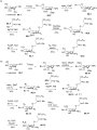
Figure 86: A) Synthesis of glucosamine ether lipids with a non-natural ʟ-glucosamine moiety; B) synthesis of e...

Figure 87: A) Structure of the most efficient anticancer agents 87.1–87.4 featuring a diamino glyco ether lipi...

Figure 88: A) Synthesis of diamino glyco ether lipid 87.4; B) synthesis of bis-glycosylated ether lipid 88.10 [256]....

Figure 89: Synthesis of triamino ether lipid 89.4 [260].

Figure 90: Synthesis of chlorambucil conjugate 90.7 [261].

Figure 91: Three main methods for the preparation of glycerol ether lipid 91.3; A) from solketal and via a tri...

Figure 92: Four different methods for the installation of the phosphocholine polar head group; A) method using...

Figure 93: Illustration of two methods for the installation of saccharides or aminosaccharides; A) O-glycosyla...
Dipeptide analogues of fluorinated aminophosphonic acid sodium salts as moderate competitive inhibitors of cathepsin C
- Karolina Wątroba,
- Małgorzata Pawełczak and
- Marcin Kaźmierczak
Beilstein J. Org. Chem. 2023, 19, 434–439, doi:10.3762/bjoc.19.33
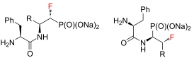
- Poznań, Uniwersytetu Poznańskiego 10, 61-614 Poznań, Poland 10.3762/bjoc.19.33 Abstract In this paper, we present the solvolysis reaction of dipeptide analogues of fluorinated aminophosphonates with simultaneous quantitative deprotection of the amino group. To the best of our knowledge, this work is the
- development of fluorinated aminophosphonate-based inhibitors. Keywords: aminophosphonates; cathepsin C; dipeptide; fluorine; solvolysis; Introduction Cathepsin C, also known as dipeptidyl peptidase I (DPPI) belongs to the family of lysosomal cysteine proteases encompassing 11 human enzymes (cathepsins B, C
- ]. Other inhibitors are dipeptide derivatives showing substrate-like sequences. One of the most effective inhibitors is the dipeptide Gly-Phe-CHN2 (glycylphenylalanine-diazomethane), which, however, has not been used as a therapeutic substance due to the instability of the diazomethylketone group [8][9

Graphical Abstract

Scheme 1: Synthetic strategy towards 5 and 7.

Scheme 2: Synthesis of 9 and 11. (a) R = -CH3; (b) R = -CH(CH3)2; (c) R = -CH2CH(CH3)2; (d) R = -CH(CH3)CH2CH3...

Figure 1: Dixon plot for the hydrolysis of Gly-Phe-pNA substrate catalyzed by bovine cathepsin C in the prese...
Inline purification in continuous flow synthesis – opportunities and challenges
- Jorge García-Lacuna and
- Marcus Baumann
Beilstein J. Org. Chem. 2022, 18, 1720–1740, doi:10.3762/bjoc.18.182
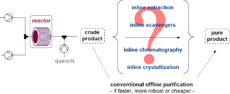
- dipeptide with the aim to overcome issues found in batch in relation to product stability and scale-up concerns. The peptide coupling reaction was performed continuously aided by a MSMPR crystallizer system. This system ultimately shortened the holding time for the quenched solution, leading to a robust

Graphical Abstract

Scheme 1: Automated in-line chromatography with the Advion puriFlash® system. The rightmost part of the schem...

Scheme 2: Purification via pH tuning and several Zaiput membranes. Redrawn from [51].

Scheme 3: Two-phase recirculating system for purifications of an immobilized enzyme-based reaction. Redrawn f...

Scheme 4: Countercurrent L–L purification using large Zaiput membranes in the presence of a phase transfer ca...

Scheme 5: General scheme of a telescoped flow process using L–L separators.

Scheme 6: Example of phase separation using a computer-vision approach. Redrawn from [68].

Scheme 7: Example of an inline purification using heterogeneous scavenging. Redrawn from [76].

Scheme 8: General scheme of a telescoped process using heterogenous cartridges.
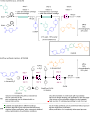
Scheme 9: Comparison of two strategies for flow-based imatinib syntheses. Redrawn from [91] and [92].

Scheme 10: General purification scheme using the catch and release strategy.

Scheme 11: Exemplar catch and release purification of a stereoselective oxidation. Redrawn from [105].

Scheme 12: Catch and release-type purification using conventional SiO2. Redrawn from [107].

Scheme 13: Schematic representation of an industrial continuous crystallization. Redrawn from [109].

Scheme 14: General scheme of an academic inline crystallization approach.

Scheme 15: Simplified overview of purification options and selected criteria.
First total synthesis of hoshinoamide A
- Haipin Zhou,
- Zihan Rui,
- Yiming Yang,
- Shengtao Xu,
- Yutian Shao and
- Long Liu
Beilstein J. Org. Chem. 2021, 17, 2924–2931, doi:10.3762/bjoc.17.201
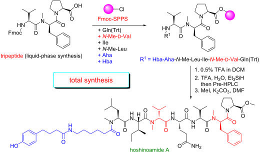
- in Scheme 1, we initially tested Fmoc solid-phase peptide synthesis (SPPS) [13] to get 2-chlorotrityl resin-bound Pro1-(N-Me)-Phe2 dipeptide 2 under the conditions of HCTU and DIPEA. Unfortunately, the N-Me coupling proceeded in low yield (<10%). In order to improve the coupling yield of the hindered
- peptide, we tried the condensation of Val3 with the dipeptide in solution. Firstly, Pro-OBn 5 was coupled with Fmoc-N-Me-ᴅ-Phe-OH by the treatment of HATU and DIPEA [14], giving dipeptide 6 in 83% yield (Scheme 2). In principle, the coupling of 6 and Fmoc-Val-OH under suitable conditions would deliver
- mL) and DCM (3 × 20 mL) to afford the resin-bound dipeptide. The resin-bound dipeptide was added to a mixture of 20% piperidine in DMF (20 mL), and the mixture was shaken for 30 minutes. Then the mixture was filtered, and the resin was washed with MeOH (3 × 20 mL) and DCM (3 × 20 mL). Fmoc-Val-OH

Graphical Abstract

Figure 1: a) Structures of hoshinoamides A and B. b) Structure of hoshinoamide C.

Scheme 1: Synthesis of resin-bound tripeptide 3 by SPPS. DIPEA: N,N-diisopropylethylamine; HCTU: O-(6-chloro-...

Scheme 2: Synthesis of dipeptide 6. HATU: 2-(7-azabenzotriazol-1-yl)-N,N,N',N'-tetramethyluronium hexafluorop...

Scheme 3: Synthesis of hoshinoamide A.
Sustainable manganese catalysis for late-stage C–H functionalization of bioactive structural motifs
- Jongwoo Son
Beilstein J. Org. Chem. 2021, 17, 1733–1751, doi:10.3762/bjoc.17.122

- cyclic peptide motif (Scheme 11). Dipeptide substrate 26f decorated with a Morita–Baylis–Hillman carbonate underwent the intramolecular C–H allylation process to yield cyclic peptide 28f under dilute reaction conditions. This macrocyclization strategy introduces an exocyclic olefin motif onto the cyclic

Graphical Abstract

Scheme 1: Mn-catalyzed late-stage fluorination of sclareolide (1) and complex steroid 3.

Figure 1: Proposed reaction mechanism of C–H fluorination by a manganese porphyrin catalyst.

Scheme 2: Late-stage radiofluorination of biologically active complex molecules.
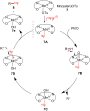
Figure 2: Proposed mechanism of C–H radiofluorination.

Scheme 3: Late-stage C–H azidation of bioactive molecules. a1.5 mol % of Mn(TMP)Cl (5) was used. bMethyl acet...

Figure 3: Proposed reaction mechanism of manganese-catalyzed C–H azidation.

Scheme 4: Mn-catalyzed late-stage C–H azidation of bioactive molecules via electrophotocatalysis. a2.5 mol % ...
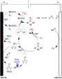
Figure 4: Proposed reaction mechanism of electrophotocatalytic azidation.
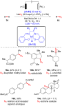
Scheme 5: Manganaelectro-catalyzed late-stage azidation of bioactive molecules.
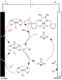
Figure 5: Proposed reaction pathway of manganaelectro-catalyzed late-stage C–H azidation.

Scheme 6: Mn-catalyzed late-stage amination of bioactive molecules. a3 Å MS were used. Protonation with HBF4⋅...

Figure 6: Proposed mechanism of manganese-catalyzed C–H amination.
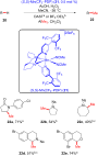
Scheme 7: Mn-catalyzed C–H methylation of heterocyclic scaffolds commonly found in small-molecule drugs. aDAS...
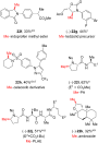
Scheme 8: Examples of late-stage C–H methylation of bioactive molecules. aDAST activation. bFor insoluble sub...
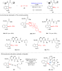
Scheme 9: A) Mn-catalyzed late-stage C–H alkynylation of peptides. B) Intramolecular late-stage alkynylative ...

Figure 7: Proposed reaction mechanism of Mn(I)-catalyzed C–H alkynylation.

Scheme 10: Late-stage Mn-catalyzed C–H allylation of peptides and bioactive motifs.

Scheme 11: Intramolecular C–H allylative cyclic peptide formation.

Scheme 12: Late-stage C–H glycosylation of tryptophan analogues.

Scheme 13: Late-stage C–H glycosylation of tryptophan-containing peptides.

Scheme 14: Late-stage C–H alkenylation of tryptophan-containing peptides.

Scheme 15: A) Late-stage C–H macrocyclization of tryptophan-containing peptides and B) traceless removal of py...
Chemical approaches to discover the full potential of peptide nucleic acids in biomedical applications
- Nikita Brodyagin,
- Martins Katkevics,
- Venubabu Kotikam,
- Christopher A. Ryan and
- Eriks Rozners
Beilstein J. Org. Chem. 2021, 17, 1641–1688, doi:10.3762/bjoc.17.116
- , appears to be the most promising conformationally constrained PNA analogue. Vilaivan and co-workers developed pyrrolidinyl PNA based on an α/β-dipeptide backbone that is one atom longer than the canonical PNA and contains two amide bonds and two cyclic moieties in one monomer (Figure 4) [61]. Cyclobutane
- ]. Interestingly and in contrast to other backbone-constrained PNAs, pyrrolidinyl α/β-dipeptide PNA formed PNA–DNA complexes having higher thermal stability compared to PNA–RNA complexes [63][64]. Most likely, the one atom longer PNA backbone, which is rigidified and preorganized by cyclic moieties, may align
- better with the B-form DNA helix rather than with the A-form RNA helix. While pyrrolidinyl α/β-dipeptide PNAs formed stable antiparallel duplexes with DNA and RNA with high mismatch intolerance, due to constrained nature, two pyrrolidinyl α/β-dipeptide PNAs had low ability to self-hybridize [62][65

Graphical Abstract

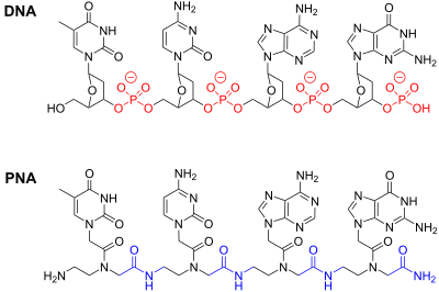
Figure 1: Structure of DNA and PNA.

Figure 2: PNA binding modes: (A) PNA–dsDNA 1:1 triplex; (B) PNA–DNA–PNA strand-invasion triplex; (C) the Hoog...

Figure 3: Structure of P-form PNA–DNA–PNA triplex from reference [41]. (A) view in the major groove and (B) view ...

Figure 4: Structures of backbone-modified PNA.

Figure 5: Structures of PNA having α- and γ-substituted backbones.

Figure 6: Structures of modified nucleobases in PNA to improve Hoogsteen hydrogen bonding to guanine and aden...

Figure 7: Proposed hydrogen bonding schemes for modified PNA nucleobases designed to recognize pyrimidines or...

Figure 8: Modified nucleobases to modulate Watson–Crick base pairing and chemically reactive crosslinking PNA...

Figure 9: Examples of triplets formed by Janus-wedge PNA nucleobases (blue). R1 denotes DNA, RNA, or PNA back...

Figure 10: Examples of fluorescent PNA nucleobases. R1 denotes DNA, RNA, or PNA backbones.

Figure 11: Endosomal entrapment and escape pathways of PNA and PNA conjugates.
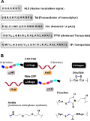
Figure 12: (A) representative cell-penetrating peptides (CPPs), (B) conjugation designs and linker chemistries....

Figure 13: Proposed delivery mode by pHLIP-PNA conjugates (A) the transmembrane section of pHLIP interacting w...

Figure 14: Structures of modified penetratin CPP conjugates with PNA linked through either disulfide (for stud...

Figure 15: Chemical structure of C9–PNA, a stable amphipathic (cyclic-peptide)–PNA conjugate.
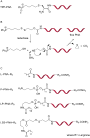
Figure 16: Structures of PNA conjugates with a lipophilic triphenylphosphonium cation (TPP–PNA) through (A) th...

Figure 17: Structures of (A) chloesteryl–PNA, (B) cholate–PNA and (C) cholate–PNA(cholate)3.

Figure 18: Structures of PNA–GalNAc conjugates (A) (GalNAc)2K, (B) triantennary (GalNAc)3, and (C) trivalent (...

Figure 19: Vitamin B12–PNA conjugates with different linkages.

Figure 20: Structures of (A) neomycin B, (B) PNA–neamine conjugate, and (C) PNA–neosamine conjugate.

Figure 21: PNA clamp (red) binding to target DNA containing a mixture of sequences (A) PNA binds with higher a...

Figure 22: Rolling circle amplification using PNA openers (red) to invade a dsDNA target forming a P-loop. A p...

Figure 23: Molecular beacons containing generic fluorophores (Fl) and quenchers (Q) recognizing a complementar...
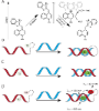
Figure 24: (A) Light-up fluorophores such as thiazole orange display fluorescence enhancement upon binding to ...

Figure 25: Templated fluorogenic detection of oligonucleotides using two PNAs. (A) Templated FRET depends on h...

Figure 26: Lateral flow devices use a streptavidin labeled strip on nitrocellulose paper to anchor a capture P...
Synthetic strategies of phosphonodepsipeptides
- Jiaxi Xu
Beilstein J. Org. Chem. 2021, 17, 461–484, doi:10.3762/bjoc.17.41
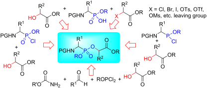
- chlorination. After the treatment of compound 39 with piperidine, the N-terminal free dipeptide was obtained and acylated with hexanedioic anhydride to afford the designed hapten 40 (Scheme 7) [11]. Phosphonodepsioctapeptide 41 was prepared as a variation of the partial sequence of a gene product of erb B-2
- the protected phosphonodepsidipeptide 126 (Scheme 21) [12], that was further converted to the designed hapten 127. The new muramyl dipeptide (MDP) phosphorus analogue 131 related to LK 423 as potential immunomodulator was prepared by the coupling of methyl 1-(N-benzyloxycarbonyl)aminoethylphosphonate

Graphical Abstract

Figure 1: Phosphonopeptides, phosphonodepsipeptides, peptides, and depsipeptides.

Figure 2: The diverse strategies for phosphonodepsipeptide synthesis.

Scheme 1: Synthesis of α-phosphonodepsidipeptides as inhibitors of leucine aminopeptidase.

Figure 3: Structure of 2-hydroxy-2-oxo-3-[(phenoxyacetyl)amino]-1,2-oxaphosphorinane-6-carboxylic acid (16).

Scheme 2: Synthesis of α-phosphonodepsidipeptide 17 as coupling partner for cyclen-containing phosphonodepsip...

Scheme 3: Synthesis of α-phosphonodepsidipeptides containing enantiopure hydroxy ester as VanX inhibitors.

Scheme 4: Synthesis of α-phosphonodepsidipeptides as VanX inhibitors.

Scheme 5: Synthesis of optically active α-phosphonodepsidipeptides as VanX inhibitors.

Scheme 6: The synthesis of phosphonodepsipeptides through a thionyl chloride-catalyzed esterification of N-Cb...

Scheme 7: Synthesis of α-phosphinodipeptidamide as a hapten.

Scheme 8: Synthesis of α-phosphonodepsioctapeptide 41.

Scheme 9: Synthesis of phosphonodepsipeptides via an in situ-generated phosphonochloridate.

Scheme 10: Synthesis of α-phosphonodepsitetrapeptides 58 as inhibitors of the aspartic peptidase pepsin.

Scheme 11: Synthesis of a β-phosphonodepsidipeptide library 64.

Scheme 12: Synthesis of another β-phosphonodepsidipeptide library.

Scheme 13: Synthesis of γ-phosphonodepsidipeptides.

Scheme 14: Synthesis of phosphonodepsipeptides 85 as folylpolyglutamate synthetase inhibitors.

Scheme 15: Synthesis of the γ-phosphonodepsitripeptide 95 as an inhibitor of γ-gutamyl transpeptidase.

Scheme 16: Synthesis of phosphonodepsipeptides as inhibitors and probes of γ-glutamyl transpeptidase.

Scheme 17: Synthesis of phosphonyl depsipeptides 108 via DCC-mediated condensation and oxidation.

Scheme 18: Synthesis of phosphonodepsipeptides 111 with BOP and PyBOP as coupling reagents.

Scheme 19: Synthesis of optically active phosphonodepsipeptides with BOP and PyBOP as coupling reagents.

Scheme 20: Synthesis of phosphonodepsipeptides with BroP and TPyCIU as coupling reagents.

Scheme 21: Synthesis of a phosphonodepsipeptide hapten with BOP as coupling reagent.

Scheme 22: Synthesis of phosphonodepsitripeptide with BOP as coupling reagent.

Scheme 23: Synthesis of norleucine-derived phosphonodepsipeptides 135 and 138.

Scheme 24: Synthesis of norleucine-derived phosphonodepsipeptides 141 and 144.

Scheme 25: Solid-phase synthesis of phosphonodepsipeptides.

Scheme 26: Synthesis of phosphonodepsidipeptides via the Mitsunobu reaction.

Scheme 27: Synthesis of γ-phosphonodepsipeptide via the Mitsunobu reaction.

Scheme 28: Synthesis of phosphonodepsipeptides via a multicomponent condensation reaction.

Scheme 29: Synthesis of phosphonodepsipeptides with a functionalized side-chain via a multicomponent condensat...

Scheme 30: High yielding synthesis of phosphonodepsipeptides via a multicomponent condensation.

Scheme 31: Synthesis of optically active phosphonodepsipeptides via a multicomponent condensation reaction.

Scheme 32: Synthesis of N-phosphoryl phosphonodepsipeptides.

Scheme 33: Synthesis of phosphonodepsipeptides via the alkylation of phosphonic monoesters.

Scheme 34: Synthesis of phosphonodepsipeptides as inhibitors of aspartic protease penicillopepsin.

Scheme 35: Synthesis of phosphonodepsipeptides as prodrugs.

Scheme 36: Synthesis of phosphonodepsithioxopeptides 198.

Scheme 37: Synthesis of phosphonodepsipeptides.

Scheme 38: Synthesis of phosphonodepsipeptides with C-1-hydroxyalkylphosphonic acid.

Scheme 39: Synthesis of phosphonodepsipeptides with C-1-hydroxyalkylphosphonate via the rhodium-catalyzed carb...

Scheme 40: Synthesis of phosphonodepsipeptides with a C-1-hydroxyalkylphosphonate motif via a copper-catalyzed...
19F NMR as a tool in chemical biology
- Diana Gimenez,
- Aoife Phelan,
- Cormac D. Murphy and
- Steven L. Cobb
Beilstein J. Org. Chem. 2021, 17, 293–318, doi:10.3762/bjoc.17.28
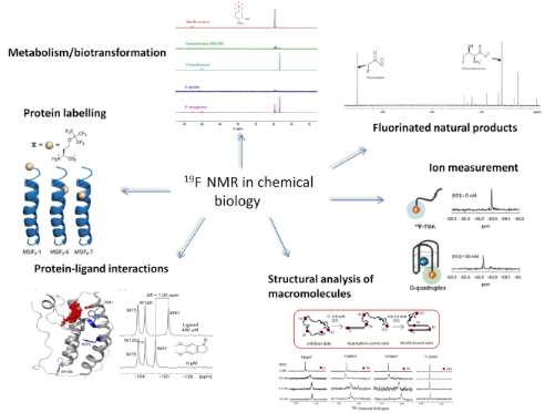

Graphical Abstract

Figure 1: Selected examples of 19F-labelled amino acid analogues used as probes in chemical biology.

Figure 2: (a) Sequences of the antimicrobial peptide MSI-78 and pFtBSer-containing analogs and cartoon repres...

Figure 3: (a) Chemical structures of a selection of trifluoromethyl tags. (b) Comparative analysis showing th...

Figure 4: (a) First bromodomain of Brd4 with all three tryptophan residues displayed in blue and labelled by ...

Figure 5: (a) Enzymatic hydroxylation of GBBNF in the presence of hBBOX (b) 19F NMR spectra showing the conve...

Figure 6: (a) In-cell enzymatic hydrolysis of the fluorinated anandamide analogue ARN1203 catalyzed by hFAAH....

Figure 7: (a) X-ray crystal structure of CAM highlighting the location the phenylalanine residues replaced by...

Figure 8: 19F PREs of 4-F, 5-F, 6-F, 7-FTrp49 containing MTSL-modified S52CCV-N. The 19F NMR resonances of ox...

Figure 9: 19F NMR as a direct probe of Ud NS1A ED homodimerization. Schematic representation showing the loca...

Figure 10: (a) Representative spectrum of a 182 μM sample of Aβ1-40-tfM35 at varying times indicating the majo...

Figure 11: Illustration of the conformational switch induced by SDS in 4-tfmF-labelled α-Syn. Also shown are t...

Figure 12: (a) Structural models of the Myc‐Max (left), Myc‐Max‐DNA (middle) and Myc‐Max‐BRCA1 complexes (righ...

Figure 13: (a) Side (left) and bottom (right) views of the pentameric apo ELIC X-ray structure (PDB ID: 3RQU) ...

Figure 14: (a) General structure of a selection of recently developed 19F-labelled nucleotides for their use a...

Figure 15: Monitoring biotransformation of the fluorinated pesticide cyhalothrin by the fungus C. elegans. The...

Figure 16: Following the biodegradation of emerging fluorinated pollutants by 19F NMR. The spectra are from cu...

Figure 17: Discovery of new fluorinated natural products by 19F NMR. The spectrum is of the culture supernatan...

Figure 18: Application of 19F NMR to investigate the biosynthesis of nucleocidin. The spectra are from culture...

Figure 19: Detection of new fluorofengycins (indicated by arrows) in culture supernatants of Bacillus sp. CS93...

Figure 20: Measurement of β-galactosidase activity in MCF7 cancer cells expressing lacZ using 19F NMR. The deg...

Figure 21: Detection of ions using 19F NMR. (a) Structure of TF-BAPTA and its 19F iCEST spectra in the presenc...

Figure 22: (a) The ONOO−-mediated decarbonylation of 5-fluoroisatin and 6-fluoroisatin. The selectivity of (b)...
Convenient access to pyrrolidin-3-ylphosphonic acids and tetrahydro-2H-pyran-3-ylphosphonates with multiple contiguous stereocenters from nonracemic adducts of a Ni(II)-catalyzed Michael reaction
- Alexander N. Reznikov,
- Dmitry S. Nikerov,
- Anastasiya E. Sibiryakova,
- Victor B. Rybakov,
- Evgeniy V. Golovin and
- Yuri N. Klimochkin
Beilstein J. Org. Chem. 2020, 16, 2073–2079, doi:10.3762/bjoc.16.174
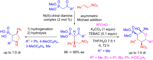
- Micromonospora [5]. Dipeptide analogs with phosphonoproline 2 and piperidine-2-phosphonic acid 3 are potent inhibitors of dipeptidyl peptidase IV [6][7]. Oxygen-containing heterocycles containing a phosphoryl group are also of interest in the development of new drugs. It is known that phosphorylated carbohydrate

Graphical Abstract
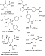
Figure 1: Pharmacologically active nonracemic phosphonates with heterocyclic moieties.
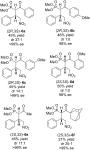
Figure 2: Starting nonracemic 4-nitro-2-oxophosphonates.

Scheme 1: Intermolecular N-methylation of reduction product 7.

Scheme 2: Synthesis of pyrrolidinyl phosphonic acids 11a–d.

Figure 3: ORTEP diagram of (2R,3R,4S)-10a.

Scheme 3: Synthesis of tetrahydropyranylphosphonates 13a–f via diastereoselective Henry/acetalyzation reactio...

Figure 4: ORTEP diagram of (2S,3R,4S,5S,6R)-13b.

Scheme 4: Synthesis of (3,4-dihydro-2H-pyran-5-yl)phosphonate 14.
Automated high-content imaging for cellular uptake, from the Schmuck cation to the latest cyclic oligochalcogenides
- Rémi Martinent,
- Javier López-Andarias,
- Dimitri Moreau,
- Yangyang Cheng,
- Naomi Sakai and
- Stefan Matile
Beilstein J. Org. Chem. 2020, 16, 2007–2016, doi:10.3762/bjoc.16.167
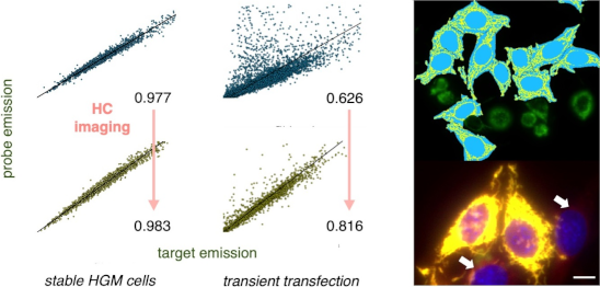
- attractive candidates for intracellular delivery. Already a small dipeptide 9 with two Schmuck amino acids shows a strong binding (KD = 100 nM) and clustering ability towards heparin due to the strong noncovalent interaction between GCP and sulfate anions, such as glycosaminoglycans (GAGs) in heparin [26

Graphical Abstract

Figure 1: Schematic representation of binding models between organic cations (simple ammonium, guanidinium, S...

Figure 2: From Schmuck cations to cell-penetrating dipeptides, with schematic representation of the binding m...

Figure 3: Peptide tweezers and cyclic peptides with Schmuck cations for gene transfection.

Figure 4: Evolution from CPPs to CPDs and COCs.

Figure 5: Structure of a) the trifunctional transporter 23 and c) the HaloTag reporter 26. b) Schematic mecha...
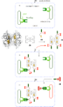
Figure 6: CAPA assay for the complex 25, composed of three transporters 23 bound to one streptavidin 24 (with...

Figure 7: Examples from the automated HC imaging of stable HGM cells with HaloTag–GFP on mitochondria, labele...
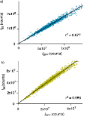
Figure 8: Evaluation of the automated HC imaging of stable HGM cells with HaloTag–GFP on mitochondria, labele...
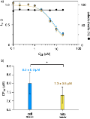
Figure 9: a) Automated HC imaging of the cellular uptake of 25, covering the concentration dependence for the...

Figure 10: Examples of automated HC imaging of transiently transfected HeLa cells with HaloTag–GFP on Golgi, l...
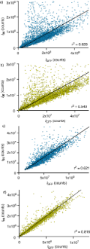
Figure 11: Evaluation of the automated HC imaging of the transiently transfected HeLa cells with HaloTag–GFP o...
A dynamic combinatorial library for biomimetic recognition of dipeptides in water
- Florian Klepel and
- Bart Jan Ravoo
Beilstein J. Org. Chem. 2020, 16, 1588–1595, doi:10.3762/bjoc.16.131
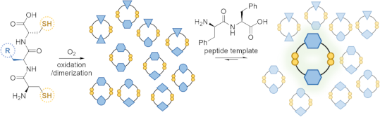
- slightly alkaline buffer (pH 7.4). An excess of our target molecules, the simple dipeptides AA, FF and YY (Y for tyrosine), were added to one sample each. An additional sample without dipeptide addition served as reference. After several hours of stirring in an open vial the thiol functions of the
- based on the dipeptide. The binding constants of YY to a(CFC)2 and p(CFC)2 are very similar and no selectivity is observed. In the interaction of FF with a(CFC)2 and p(CFC)2 the enthalpy is very low, which is cause for a poor signal-to-noise ratio. Other values for these particular interactions should

Graphical Abstract

Scheme 1: a) Building blocks included in this study. b) Antiparallel and parallel constitutional isomers of t...

Figure 1: HPLC–MS chromatograms of a reference library for all possible tripeptide dimers ([M + H]+ ions).

Figure 2: a) HPLC–MS chromatograms of the dimers (CFC)2 and templates YY and FF. b) Amplification of the peak...

Scheme 2: a) Synthesis of the parallel and antiparallel isomers p(CFC)2 and a(CFC)2. b) Templates FF. YY and ...

Figure 3: ITC of YY (30 mM) to a(CFC)2 (1.5 mM) in phosphate buffer (pH 7.4, 100 mM).

Figure 4: Continuously varied NMR measurements of a) p(CFC)2 to YY b) p(CFC)2 to FF c) a(CFC)2 to YY d) a(CFC)...

Figure 5: Job plots derived from the continuously varied NMR measurements of a) p(CFC)2 to YY b) p(CFC)2 to FF...
Fluorinated phenylalanines: synthesis and pharmaceutical applications
- Laila F. Awad and
- Mohammed Salah Ayoup
Beilstein J. Org. Chem. 2020, 16, 1022–1050, doi:10.3762/bjoc.16.91
- synthesized by alkylation of 26a,b with the chiral auxiliary 31, which was obtained by reaction of the cyclic dipeptide 30 with triethyloxonium tetrafluoroborate. The alkylation reaction of 26a,b was carried out with n-BuLi in THF at −78 °C to give 32a,b. Acid hydrolysis of the alkylated product 32a,b

Graphical Abstract

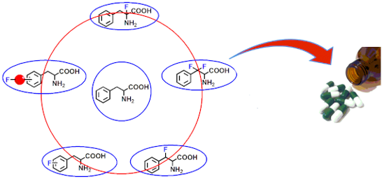
Figure 1: Categories I–V of fluorinated phenylalanines.

Scheme 1: Synthesis of fluorinated phenylalanines via Jackson’s method.

Scheme 2: Synthesis of all-cis-tetrafluorocyclohexylphenylalanines.

Scheme 3: Synthesis of ʟ-4-[sulfono(difluoromethyl)]phenylalanine (nPt: neopentyl, TCE: trichloroethyl).

Scheme 4: Synthesis of ʟ-4-[sulfono(difluoromethyl)]phenylalanine derivatives 17.

Scheme 5: Synthesis of fluorinated Phe analogues from Cbz-protected aminomalonates.

Scheme 6: Synthesis of tetrafluorophenylalanine analogues via the 3-methyl-4-imidazolidinone auxiliary 25.

Scheme 7: Synthesis of tetrafluoro-Phe derivatives via chiral auxiliary 31.

Scheme 8: Synthesis of 2,5-difluoro-Phe and 2,4,5-trifluoro-Phe via Schöllkopf reagent 34.

Scheme 9: Synthesis of 2-fluoro- and 2,6-difluoro Fmoc-Phe derivatives starting from chiral auxiliary 39.

Scheme 10: Synthesis of 2-[18F]FPhe via chiral auxiliary 43.

Scheme 11: Synthesis of FPhe 49a via photooxidative cyanation.

Scheme 12: Synthesis of FPhe derivatives via Erlenmeyer azalactone synthesis.

Scheme 13: Synthesis of (R)- and (S)-2,5-difluoro Phe via the azalactone method.

Scheme 14: Synthesis of 3-bromo-4-fluoro-(S)-Phe (65).

Scheme 15: Synthesis of [18F]FPhe via radiofluorination of phenylalanine with [18F]F2 or [18F]AcOF.

Scheme 16: Synthesis of 4-borono-2-[18F]FPhe.

Scheme 17: Synthesis of protected 4-[18F]FPhe via arylstannane derivatives.

Scheme 18: Synthesis of FPhe derivatives via intermediate imine formation.

Scheme 19: Synthesis of FPhe derivatives via Knoevenagel condensation.

Scheme 20: Synthesis of FPhe derivatives 88a,b from aspartic acid derivatives.

Scheme 21: Synthesis of 2-(2-fluoroethyl)phenylalanine derivatives 93 and 95.

Scheme 22: Synthesis of FPhe derivatives via Zn2+ complexes.

Scheme 23: Synthesis of FPhe derivatives via Ni2+ complexes.

Scheme 24: Synthesis of 3,4,5-trifluorophenylalanine hydrochloride (109).

Scheme 25: Synthesis of FPhe derivatives via phenylalanine aminomutase (PAM).

Scheme 26: Synthesis of (R)-2,5-difluorophenylalanine 115.

Scheme 27: Synthesis of β-fluorophenylalanine via 2-amino-1,3-diol derivatives.

Scheme 28: Synthesis of β-fluorophenylalanine derivatives via the oxazolidinone chiral auxiliary 122.

Scheme 29: Synthesis of β-fluorophenylalanine from pyruvate hemiketal 130.

Scheme 30: Synthesis of β-fluorophenylalanine (136) via fluorination of β-hydroxyphenylalanine (137).

Scheme 31: Synthesis of β-fluorophenylalanine from aziridine derivatives.

Scheme 32: Synthesis of β-fluorophenylalanine 136 via direct fluorination of pyruvate esters.

Scheme 33: Synthesis of β-fluorophenylalanine via fluorination of ethyl 3-phenylpyruvate enol using DAST.

Scheme 34: Synthesis of β-fluorophenylalanine derivatives using photosensitizer TCB.

Scheme 35: Synthesis of β-fluorophenylalanine derivatives using Selectflour and dibenzosuberenone.

Scheme 36: Synthesis of protected β-fluorophenylalanine via aziridinium intermediate 150.

Scheme 37: Synthesis of β-fluorophenylalanine derivatives via fluorination of α-hydroxy-β-aminophenylalanine d...

Scheme 38: Synthesis of β-fluorophenylalanine derivatives from α- or β-hydroxy esters 152a and 155.

Scheme 39: Synthesis of a series of β-fluoro-Phe derivatives via Pd-catalyzed direct fluorination of β-methyle...

Scheme 40: Synthesis of series of β-fluorinated Phe derivatives using quinoline-based ligand 162 in the Pd-cat...

Scheme 41: Synthesis of β,β-difluorophenylalanine derivatives from 2,2-difluoroacetaldehyde derivatives 164a,b....

Scheme 42: Synthesis of β,β-difluorophenylalanine derivatives via an imine chiral auxiliary.

Scheme 43: Synthesis of α-fluorophenylalanine derivatives via direct fluorination of protected Phe 174.

Figure 2: Structures of PET radiotracers of 18FPhe derivatives.

Figure 3: Structures of melfufen (179) and melphalan (180) anticancer drugs.

Figure 4: Structure of gastrazole (JB95008, 181), a CCK2 receptor antagonist.

Figure 5: Dual CCK1/CCK2 antagonist 182.

Figure 6: Structure of sitagliptin (183), an antidiabetic drug.

Figure 7: Structure of retaglpitin (184) and antidiabetic drug.

Figure 8: Structure of evogliptin (185), an antidiabetic drug.

Figure 9: Structure of LY2497282 (186) a DPP-4 inhibitor for the treatment of type II diabetes.

Figure 10: Structure of ulimorelin (187).

Figure 11: Structure of GLP1R (188).
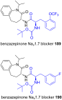
Figure 12: Structures of Nav1.7 blockers 189 and 190.
Fabclavine diversity in Xenorhabdus bacteria
- Sebastian L. Wenski,
- Harun Cimen,
- Natalie Berghaus,
- Sebastian W. Fuchs,
- Selcuk Hazir and
- Helge B. Bode
Beilstein J. Org. Chem. 2020, 16, 956–965, doi:10.3762/bjoc.16.84
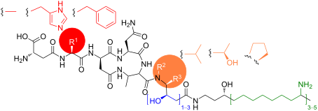
- identified. These are generated when the peptide biosynthesis starts directly with the second NRPS enzyme FclJ, which results in the formation of a dipeptide instead of the usual hexapeptide (Figure 1) [22]. Structurally related compounds are the (pre)zeamines described for Serratia plymuthica and Dickeya

Graphical Abstract

Figure 1: General biosynthesis of fabclavine Ia (1) in X. budapestensis (A) and representation of a shortened...

Figure 2: Comparison of the fcl BGCs in Xenorhabdus and Photorhabdus strains responsible for the fabclavine b...
Synthesis of new asparagine-based glycopeptides for future scanning tunneling microscopy investigations
- Laura Sršan and
- Thomas Ziegler
Beilstein J. Org. Chem. 2020, 16, 888–894, doi:10.3762/bjoc.16.80
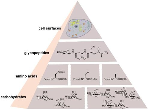
- Table 1, the yields for all condensations with HBTU and HATU are in a comparable range. Only for the cellobiosyl Asp amino acid 3f (Table 1, entry 6), the lactosylated Asp–Phe–Ala tripeptide 6e (Table 1, entry 23), and the galactosylated Asp–Trp dipeptide 5b (Table 1, entry 14), HATU gave a

Graphical Abstract

Scheme 1: Description of the starting materials 1a–f and 2a–f.
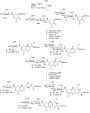
Scheme 2: Peptide coupling reactions, including the previous Fmoc cleavage.
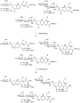
Scheme 3: Cleavage of the fully protected peptides 6 and 7.
Efficient synthesis of dipeptide analogues of α-fluorinated β-aminophosphonates
- Marcin Kaźmierczak and
- Henryk Koroniak
Beilstein J. Org. Chem. 2020, 16, 756–762, doi:10.3762/bjoc.16.69
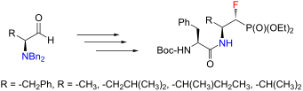
- Herein, we present an efficient synthesis of dipeptide analogues of α-fluorinated β-aminophosphonates. Each step of the synthesis was optimized to provide excellent yields. Moreover, the absolute configuration of the obtained compounds was determined by X-ray analysis, which proved the stereochemistry
- that was proposed based on NMR studies. Keywords: dipeptide analogues; fluorinated aminophosphonates; fluorine; nucleophilic fluorination; phosphorus; Introduction The chemistry of fluorinated aminophosphonates is constantly being developed, mainly due to their wide spectra of applications. What is
- regioselectivity of the fluorination reaction. The absolute configuration of the obtained compounds was determined and confirmed by X-ray analysis. Furthermore, we present the use of α-fluorinated β-aminophosphonates as building blocks in the synthesis of their dipeptide analogues. In addition, we show the results

Graphical Abstract

Figure 1: Chemical structure of PyFluor, PBSF and SulfoxFluor.

Scheme 1: Synthesis of 5.

Figure 2: Chemical structure bases.

Scheme 2: Synthesis of 11.

Scheme 3: Synthesis of 13 and 14.

Figure 3: Molecular structure of compound (1R,2S)-14c (ORTEP image).

Scheme 4: Synthesis of 15. aConditions are given in the Experimental section.
Chemical synthesis of tripeptide thioesters for the biotechnological incorporation into the myxobacterial secondary metabolite argyrin via mutasynthesis
- David C. B. Siebert,
- Roman Sommer,
- Domen Pogorevc,
- Michael Hoffmann,
- Silke C. Wenzel,
- Rolf Müller and
- Alexander Titz
Beilstein J. Org. Chem. 2019, 15, 2922–2929, doi:10.3762/bjoc.15.286
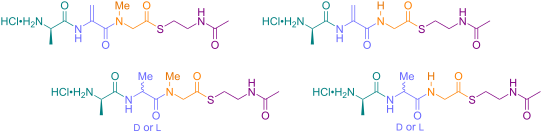
- sarcosine (Sar) and derivatives. Chemical synthesis of the native sequence ᴅ-Ala-Dha-Sar thioester required revision of the sequential peptide synthesis into a convergent strategy where the thioester with sarcosine was formed before coupling to the Dha-containing dipeptide. Keywords: antibiotic; argyrin
- -ᴅ-Ala (16) was coupled to O-benzylserine ethyl ester 37 to give dipeptide 38, hydrogenolytic debenzylation gave the substrate 39 for the copper(I)-mediated elimination of the carbodiimide formed in situ using EDC, and then yielded the dipeptide Boc-ᴅ-Ala-Dha ester 40 in good yields. Lithium
- desired thioester probably due to the higher reactivity of the Michael acceptor system. Revision of the synthetic approach into a convergent synthesis with initial formation of the thioester at the amino acid level and subsequent coupling to a dipeptide finally yielded the desired mutasynthon carrying the

Graphical Abstract
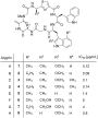
Figure 1: Chemical structures of naturally occurring argyrins with potent antipseudomonal activity.

Figure 2: The biosynthetic pathway for argyrin production in Cystobacter sp. SBCb004 (Arg1, radical SAM-depen...

Figure 3: Designed mutasynthons 9–14 for argyrin biosynthesis. Peptides are based on three amino acids and ad...

Scheme 1: Synthesis of tripeptide thioesters. Reagents and conditions: (a) SOCl2, EtOH, 78 °C; (b) IBCF, NMM,...
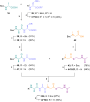
Scheme 2: Improved synthesis of the tripeptide thioester 14. Reagents and conditions: (a) SOCl2, EtOH, 78 °C;...
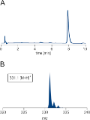
Figure 4: Analysis of mutasynthon 14 obtained via the convergent synthetic route by HPLC on a HILIC stationar...