Search results
Search for "ethynyl" in Full Text gives 124 result(s) in Beilstein Journal of Organic Chemistry.
Synthesis of novel alkynyl imidazopyridinyl selenides: copper-catalyzed tandem selenation of selenium with 2-arylimidazo[1,2-a]pyridines and terminal alkynes
- Mio Matsumura,
- Kaho Tsukada,
- Kiwa Sugimoto,
- Yuki Murata and
- Shuji Yasuike
Beilstein J. Org. Chem. 2022, 18, 863–871, doi:10.3762/bjoc.18.87

- phenyllithium in THF at −78 °C led to a nucleophilic substitution reaction with the elimination of the ethynyl group to form the desired phenylimidazopyridinyl selenide 6a in 49% yield. In the reaction with n-butyllithium, alkyl derivative 6b was isolated in the same way. The reaction of 4aa with the Ruppert

Graphical Abstract

Figure 1: Biologically active selenides having alkynyl or imidazopyridinyl groups.

Figure 2: (a) ORTEP drawing of 4aa and (b) its stacking structure.

Scheme 1: Control reactions.

Figure 3: Proposed mechanism.

Scheme 2: Transformation from 4aa.
Advances in mercury(II)-salt-mediated cyclization reactions of unsaturated bonds
- Sumana Mandal,
- Raju D. Chaudhari and
- Goutam Biswas
Beilstein J. Org. Chem. 2021, 17, 2348–2376, doi:10.3762/bjoc.17.153

- with HgCl2 (0.5 equiv) in presence of N-bromosuccinimide (NBS) undergoes cyclization yielding stable bromo alkenes 87 (Scheme 28) [80][81]. Atta et al. reported the specific cyclization of ethynyl phenols 88 in presence of HgCl2 at ambient temperature yielding benzofuran derivatives 89. They had

Graphical Abstract

Scheme 1: Schematic representation of Hg(II)-mediated addition to an unsaturated bond.

Scheme 2: First report of Hg(II)-mediated synthesis of 2,5-dioxane derivatives from allyl alcohol.

Scheme 3: Stepwise synthesis of 2,6-distubstituted dioxane derivatives.

Scheme 4: Cyclization of carbohydrate alkene precursor.

Scheme 5: Hg(II)-mediated synthesis of C-glucopyranosyl derivatives.

Scheme 6: Synthesis of C-glycosyl amino acid derivative using Hg(TFA)2.

Scheme 7: Hg(OAc)2-mediated synthesis of α-ᴅ-ribose derivative.

Scheme 8: Synthesis of β-ᴅ-arabinose derivative 18.

Scheme 9: Hg(OAc)2-mediated synthesis of tetrahydrofuran derivatives.

Scheme 10: Synthesis of Hg(TFA)2-mediated bicyclic nucleoside derivative.

Scheme 11: Synthesis of pyrrolidine and piperidine derivatives.

Scheme 12: HgCl2-mediated synthesis of diastereomeric pyrrolidine derivatives.

Scheme 13: HgCl2-mediated cyclization of alkenyl α-aminophosphonates.

Scheme 14: Cyclization of 4-cycloocten-1-ol with Hg(OAc)2 forming fused bicyclic products.

Scheme 15: trans-Amino alcohol formation through Hg(II)-salt-mediated cyclization.

Scheme 16: Hg(OAc)2-mediated 2-aza- or 2-oxa-bicyclic ring formations.

Scheme 17: Hg(II)-salt-induced cyclic peroxide formation.

Scheme 18: Hg(OAc)2-mediated formation of 1,2,4-trioxanes.

Scheme 19: Endocyclic enol ether derivative formation through Hg(II) salts.

Scheme 20: Synthesis of optically active cyclic alanine derivatives.

Scheme 21: Hg(II)-salt-mediated formation of tetrahydropyrimidin-4(1H)-one derivatives.

Scheme 22: Cyclization of ether derivatives to form stereoselective oxazolidine derivatives.

Scheme 23: Cyclization of amide derivatives induced by Hg(OAc)2.

Scheme 24: Hg(OAc)2/Hg(TFA)2-promoted cyclization of salicylamide-derived amidal auxiliary derivatives.

Scheme 25: Hg(II)-salt-mediated cyclization to form dihydrobenzopyrans.

Scheme 26: HgCl2-induced cyclization of acetylenic silyl enol ether derivatives.

Scheme 27: Synthesis of exocyclic and endocyclic enol ether derivatives.

Scheme 28: Cyclization of trans-acetylenic alcohol by treatment with HgCl2.

Scheme 29: Synthesis of benzofuran derivatives in presence of HgCl2.

Scheme 30: a) Hg(II)-salt-mediated cyclization of 4-hydroxy-2-alkyn-1-ones to furan derivatives and b) its mec...

Scheme 31: Cyclization of arylacetylenes to synthesize carbocyclic and heterocyclic derivatives.

Scheme 32: Hg(II)-salt-promoted cyclization–rearrangement to form heterocyclic compounds.

Scheme 33: a) HgCl2-mediated cyclization reaction of tethered alkyne dithioacetals; and b) proposed mechanism.

Scheme 34: Cyclization of aryl allenic ethers on treatment with Hg(OTf)2.

Scheme 35: Hg(TFA)2-mediated cyclization of allene.

Scheme 36: Hg(II)-catalyzed intramolecular trans-etherification reaction of 2-hydroxy-1-(γ-methoxyallyl)tetrah...

Scheme 37: a) Cyclization of alkene derivatives by catalytic Hg(OTf)2 salts and b) mechanism of cyclization.

Scheme 38: a) Synthesis of 1,4-dihydroquinoline derivatives by Hg(OTf)2 and b) plausible mechanism of formatio...

Scheme 39: Synthesis of Hg(II)-salt-catalyzed heteroaromatic derivatives.

Scheme 40: Hg(II)-salt-catalyzed synthesis of dihydropyranone derivatives.

Scheme 41: Hg(II)-salt-catalyzed cyclization of alkynoic acids.

Scheme 42: Hg(II)-salt-mediated cyclization of alkyne carboxylic acids and alcohol to furan, pyran, and spiroc...

Scheme 43: Hg(II)-salt-mediated cyclization of 1,4-dihydroxy-5-alkyne derivatives.

Scheme 44: Six-membered morpholine derivative formation by catalytic Hg(II)-salt-induced cyclization.

Scheme 45: Hg(OTf)2-catalyzed hydroxylative carbocyclization of 1,6-enyne.

Scheme 46: a) Hg(OTf)2-catalyzed hydroxylative carbocyclization of 1,6-enyne. b) Proposed mechanism.

Scheme 47: a) Synthesis of carbocyclic derivatives using a catalytic amount of Hg(II) salt. b) Proposed mechan...

Scheme 48: Cyclization of 1-alkyn-5-ones to 2-methylfuran derivatives.

Scheme 49: Hg(NO3)2-catalyzed synthesis of 2-methylenepiperidine.

Scheme 50: a) Preparation of indole derivatives through cycloisomerization of 2-ethynylaniline and b) its mech...

Scheme 51: a) Hg(OTf)2-catalyzed synthesis of 3-indolinones and 3-coumaranones and b) simplified mechanism.

Scheme 52: a) Hg(OTf)2-catalyzed one pot cyclization of nitroalkyne and b) its plausible mechanism.

Scheme 53: Synthesis of tricyclic heterocyclic scaffolds.

Scheme 54: HgCl2-mediated cyclization of 2-alkynylphenyl alkyl sulfoxide.

Scheme 55: a) Hg(OTf)2-catalyzed cyclization of allenes and alkynes. b) Proposed mechanism of cyclization.

Scheme 56: Stereoselective synthesis of tetrahydropyran derivatives.

Scheme 57: a) Hg(ClO4)2-catalyzed cyclization of α-allenol derivatives. b) Simplified mechanism.

Scheme 58: Hg(TFA)2-promoted cyclization of a γ-hydroxy alkene derivative.

Scheme 59: Synthesis Hg(II)-salt-mediated cyclization of allyl alcohol for the construction of ventiloquinone ...

Scheme 60: Hg(OAc)2-mediated cyclization as a key step for the synthesis of hongconin.

Scheme 61: Examples of Hg(II)-salt-mediated cyclized ring formation in the syntheses of (±)-fastigilin C and (...

Scheme 62: Formal synthesis of (±)-thallusin.

Scheme 63: Total synthesis of hippuristanol and its analog.

Scheme 64: Total synthesis of solanoeclepin A.

Scheme 65: a) Synthesis of Hg(OTf)2-catalyzed azaspiro structure for the formation of natural products. b) Pro...
Chemical syntheses and salient features of azulene-containing homo- and copolymers
- Vijayendra S. Shetti
Beilstein J. Org. Chem. 2021, 17, 2164–2185, doi:10.3762/bjoc.17.139

- -(n-dodecyl)azulene (16) is shown in Scheme 5A. The Sonogashira cross-coupling reaction between 4,7-dibromo-6-(n-dodecyl)azulene (13) and 4,7-diethynyl-6-(n-dodecyl)azulene (16) yielded 4,7-polyazulene 17 linked through ethynyl bridges (Scheme 5B). Similarly, the Yamamoto cross-coupling reaction
- backbone, resulting in the blue shift of absorption bands (λmax around 350 nm). Interestingly, the ethynyl linker in 17 was assisting the effective delocalization despite the presence of the n-alkyl group at position 6, as evidenced by its large red-shifted absorption at 456 nm compared to 19. The
- ) complexes. Synthesis of ‘true polyazulene’ 3 or 3’ by cationic polymerization. Synthesis of 1,3-polyazulene 5 by Yamamoto protocol. Synthesis of 4,7-dibromo-6-(n-alkyl)azulenes 12–14. Synthesis of (A) 4,7-diethynyl-6-(n-dodecyl)azulene (16) and (B) 4,7-polyazulene 17 containing an ethynyl spacer. Synthesis

Graphical Abstract

Figure 1: Chemical structure, numbering scheme, and resonance form of azulene.

Scheme 1: Synthesis of polyazulene-iodine (PAz-I2) and polyazulene-bromine (PAz-Br2) complexes.

Scheme 2: Synthesis of ‘true polyazulene’ 3 or 3’ by cationic polymerization.

Scheme 3: Synthesis of 1,3-polyazulene 5 by Yamamoto protocol.

Scheme 4: Synthesis of 4,7-dibromo-6-(n-alkyl)azulenes 12–14.

Scheme 5: Synthesis of (A) 4,7-diethynyl-6-(n-dodecyl)azulene (16) and (B) 4,7-polyazulene 17 containing an e...

Scheme 6: Synthesis of directly connected 4,7-polyazulenes 18–20.

Scheme 7: Synthesis of (A) tert-butyl N-(6-bromoazulen-2-yl)carbamate (27), (B) dimeric aminoazulene 29, and ...

Figure 2: Iminium zwitterionic resonance forms of poly[2(6)-aminoazulene] 31.

Scheme 8: Synthesis of poly{1,3-bis[2-(3-alkylthienyl)]azulene} 33–38.

Scheme 9: Synthesis of polymer ruthenium complexes 40–43.

Scheme 10: Synthesis of 4,7-polyazulenes 45 containing a thienyl linker.

Scheme 11: Synthesis of azulene-bithiophene 48 and azulene-benzothiadiazole 52 copolymers. Conditions: (a): (i...

Scheme 12: Synthesis of azulene-benzodithiophene copolymer 54 and azulene-bithiophene copolymer 56.

Scheme 13: Synthesis of (A) 5,5’-bis(trimethylstannyl)-3,3’-didodecyl-2,2’-bithiophene (60) and (B) azulene-bi...

Scheme 14: Synthesis of 1,3-bisborylated azulene 67.

Scheme 15: Synthesis of D–A-type azulene-DPP copolymers 69, 71, and 72. Conditions: (a) Pd(PPh3)4, K2CO3, Aliq...

Scheme 16: Synthesis of the key precursor TBAzDI 79.

Scheme 17: Synthesis of TBAzDI-based polymers 81 and 83. Conditions: (a) P(o-tol)3, Pd2(dba)3, PivOH, Cs2CO3, ...

Scheme 18: Synthesis of (A) 1,3-dibromo-2-arylazulene 92–98 and (B) 2-arylazulene-thiophene copolymers 99–101.

Scheme 19: Synthesis of (A) poly[2,7-(9,9-dialkylfluorenyl)-alt-(1’,3’-azulenyl)] 106–109, (B) 1,3-bis(7-bromo...

Scheme 20: Synthesis of azulene-fluorene copolymers 117–121 containing varying ratios of 1,3- and 4,7-connecte...

Scheme 21: Synthesis of (A) 2,6-dibromoazulene (125), (B) azulene-fluorene copolymer 126, and (C) azulene-fluo...

Scheme 22: Synthesis of 2-arylazulene-fluorene copolymers 131–134.

Scheme 23: Synthesis of azulene-fluorene-benzothiadiazole terpolymers 136–138.

Scheme 24: Synthesis of azulene-carbazole-benzothiadiazole-conjugated polymers 140–144.

Scheme 25: Synthesis of (A) azulene-2-yl methacrylate (146) and (B) the triazole-containing azulene methacryla...

Scheme 26: Synthesis of (A) azulene methacrylate polymer 151 and (B) triazole-containing azulene methacrylate ...

Scheme 27: Synthesis of azulene methyl methacrylate polymers 154, 155 (A and B) and azulene-sulfobetaine metha...
Recent advances in the syntheses of anthracene derivatives
- Giovanni S. Baviera and
- Paulo M. Donate
Beilstein J. Org. Chem. 2021, 17, 2028–2050, doi:10.3762/bjoc.17.131

- aromatic ketones (Scheme 27) [61]. The authors coupled acetophenone derivatives 116 and 1,4-benzenediboronates 117 at a 2:1 ratio, to obtain p-terphenyl derivatives 118. In the second step, the conversion of the acetyl group of compounds 118 to an ethynyl group afforded diethynylterphenyls 119. In the last
- double cyclization and concluded that the reaction strongly depended on the position of the ethynyl groups in the terphenyl compounds. Terphenyls 125 were the most appropriate to prepare dibenzo[a,h]anthracenes in good yield (49–92%). AuCl was a notable catalyst because it maintained high cyclization

Graphical Abstract

Figure 1: Examples of anthracene derivatives and their applications.

Scheme 1: Rhodium-catalyzed oxidative coupling reactions of arylboronic acids with internal alkynes.

Scheme 2: Rhodium-catalyzed oxidative benzannulation reactions of 1-adamantoyl-1-naphthylamines with internal...

Scheme 3: Gold/bismuth-catalyzed cyclization of o-alkynyldiarylmethanes.

Scheme 4: [2 + 2 + 2] Cyclotrimerization reactions with alkynes/nitriles in the presence of nickel and cobalt...

Scheme 5: Cobalt-catalyzed [2 + 2 + 2] cyclotrimerization reactions with bis(trimethylsilyl)acetylene (23).

Scheme 6: [2 + 2 + 2] Alkyne-cyclotrimerization reactions catalyzed by a CoCl2·6H2O/Zn reagent.

Scheme 7: Pd(II)-catalyzed sp3 C–H alkenylation of diphenyl carboxylic acids with acrylates.

Scheme 8: Pd(II)-catalyzed sp3 C–H arylation with o-tolualdehydes and aryl iodides.

Scheme 9: Alkylation of arenes with aromatic aldehydes in the presence of acetyl bromide and ZnBr2/SiO2.

Scheme 10: BF3·H2O-catalyzed hydroxyalkylation of arenes with aromatic dialdehyde 44.

Scheme 11: Bi(OTf)3-promoted Friedel–Crafts alkylation of triarylmethanes and aromatic acylals and of arenes a...

Scheme 12: Reduction of anthraquinones by using Zn/pyridine or Zn/NaOH reductive methods.

Scheme 13: Two-step route to novel substituted Indenoanthracenes.

Scheme 14: Synthesis of 1,8-diarylanthracenes through Suzuki–Miyaura coupling reaction in the presence of Pd-P...

Scheme 15: Synthesis of five new substituted anthracenes by using LAH as reducing agent.

Scheme 16: One-pot procedure to synthesize substituted 9,10-dicyanoanthracenes.

Scheme 17: Reduction of bromoanthraquinones with NaBH4 in alkaline medium.

Scheme 18: In(III)-catalyzed reductive-dehydration intramolecular cycloaromatization of 2-benzylic aromatic al...

Scheme 19: Acid-catalyzed cyclization of new O-protected ortho-acetal diarylmethanols.

Scheme 20: Lewis acid-mediated regioselective cyclization of asymmetric diarylmethine dipivalates and diarylme...

Scheme 21: BF3·OEt2/CF3SO3H-mediated cyclodehydration reactions of 2-(arylmethyl)benzaldehydes and 2-(arylmeth...

Scheme 22: Synthesis of 2,3,6,7-anthracenetetracarbonitrile (90) by double Wittig reaction followed by deprote...

Scheme 23: Homo-elongation protocol for the synthesis of substituted acene diesters/dinitriles.

Scheme 24: Synthesis of two new parental BN anthracenes via borylative cyclization.

Scheme 25: Synthesis of substituted anthracenes from a bifunctional organomagnesium alkoxide.

Scheme 26: Palladium-catalyzed tandem C–H activation/bis-cyclization of propargylic carbonates.

Scheme 27: Ruthenium-catalyzed C–H arylation of acetophenone derivatives with arenediboronates.

Scheme 28: Pd-catalyzed intramolecular cyclization of (Z,Z)-p-styrylstilbene derivatives.

Scheme 29: AuCl-catalyzed double cyclization of diiodoethynylterphenyl compounds.

Scheme 30: Iodonium-induced electrophilic cyclization of terphenyl derivatives.

Scheme 31: Oxidative photocyclization of 1,3-distyrylbenzene derivatives.

Scheme 32: Oxidative cyclization of 2,3-diphenylnaphthalenes.

Scheme 33: Suzuki-Miyaura/isomerization/ring closing metathesis strategy to synthesize benz[a]anthracenes.

Scheme 34: Green synthesis of oxa-aza-benzo[a]anthracene and oxa-aza-phenanthrene derivatives.

Scheme 35: Triple benzannulation of substituted naphtalene via a 1,3,6-naphthotriyne synthetic equivalent.

Scheme 36: Zinc iodide-catalyzed Diels–Alder reactions with 1,3-dienes and aroyl propiolates followed by intra...

Scheme 37: H3PO4-promoted intramolecular cyclization of substituted benzoic acids.

Scheme 38: Palladium-catalyzed intermolecular direct acylation of aromatic aldehydes and o-iodoesters.

Scheme 39: Cycloaddition/oxidative aromatization of quinone and β-enamino esters.

Scheme 40: ʟ-Proline-catalyzed [4 + 2] cycloaddition reaction of naphthoquinones and α,β-unsaturated aldehydes....

Scheme 41: Iridium-catalyzed [2 + 2 + 2] cycloaddition of a 1,2-bis(propiolyl)benzene derivative with alkynes.

Scheme 42: Synthesis of several anthraquinone derivatives by using InCl3 and molecular iodine.

Scheme 43: Indium-catalyzed multicomponent reactions employing 2-hydroxy-1,4-naphthoquinone (186), β-naphthol (...

Scheme 44: Synthesis of substituted anthraquinones catalyzed by an AlCl3/MeSO3H system.

Scheme 45: Palladium(II)-catalyzed/visible light-mediated synthesis of anthraquinones.

Scheme 46: [4 + 2] Anionic annulation reaction for the synthesis of substituted anthraquinones.
2,4-Bis(arylethynyl)-9-chloro-5,6,7,8-tetrahydroacridines: synthesis and photophysical properties
- Najeh Tka,
- Mohamed Adnene Hadj Ayed,
- Mourad Ben Braiek,
- Mahjoub Jabli,
- Noureddine Chaaben,
- Kamel Alimi,
- Stefan Jopp and
- Peter Langer
Beilstein J. Org. Chem. 2021, 17, 1629–1640, doi:10.3762/bjoc.17.115

- prepared products are given in Table 4. For phenylethynyl-substituted product 4a, the blue colored surface, located mainly at the cyclohexane ring, visualizes the electron deficiency. While the red region, localized essentially at the nitrogen atom and its closer ethynyl group, show the electron abundance
- rings. For product 4f, the high electron-deficient effect of the trifluoromethyl groups induces the appearance of blue surfaces around the tetrahydroacridine core, the ethynyl groups and the external phenyl rings, indicating a significant decrease of their electronic densities. However, a yellow-red
- region is added to the electrostatic map of compound 4g, due to the positive mesomeric effect of the π-donating methoxy substituent. Accordingly, we conclude that substituents at the introduced arylethynyl groups can communicate electronically with the central tetrahydroacridine core via the ethynyl

Graphical Abstract

Figure 1: Applications of acridines.

Scheme 1: Synthesis of 2,4-dibromo-9-chloro-5,6,7,8-tetrahydroacridine (2).

Scheme 2: Synthesis of 2,4-bis(arylethynyl)-9-chloro-5,6,7,8-tetrahydroacridines 4a–g.

Figure 2: UV–vis absorption spectra of 4a,b and 4e–g in diluted dichloromethane solutions at room temperature...

Figure 3: Emission spectra of 4a,b and 4e–g in diluted dichloromethane solutions at room temperature (c = 1 ×...
A recent overview on the synthesis of 1,4,5-trisubstituted 1,2,3-triazoles
- Pezhman Shiri,
- Ali Mohammad Amani and
- Thomas Mayer-Gall
Beilstein J. Org. Chem. 2021, 17, 1600–1628, doi:10.3762/bjoc.17.114

- (Scheme 38) [61]. A number of 4-ethynyl-5-iodo-1,2,3-triazoles 134 have been synthesized through the Cu-catalyzed 1,3-dipolar cycloaddition of iododiacetylenes 132 with organic azides 133 using CuI(PPh3)3 and 2,6-lutidine as a catalytic system at room temperature. Then, 4-ethynyl-5-iodo-1,2,3-triazoles
- −Miyaura cross-coupling produced a series of 5-aryl-4-ethynyl triazoles 136 in the presence of Pd(PPh3)4 as catalyst and K3PO4 as base in 1,4-dioxane as solvent at 100 °C (Scheme 39) [62]. A paper by Sekar et al. described the synthesis of polycyclic triazoles 142 through a domino alkyne insertion and C–H

Graphical Abstract

Figure 1: Some significant triazole derivatives [8,23-27].

Scheme 1: A general comparison between synthetic routes for disubstituted 1,2,3-triazole derivatives and full...

Scheme 2: Synthesis of formyltriazoles 3 from the treatment of α-bromoacroleins 1 with azides 2.

Scheme 3: A probable mechanism for the synthesis of formyltriazoles 5 from the treatment of α-bromoacroleins 1...

Scheme 4: Synthesis of 1,4,5-trisubstituted 1,2,3-triazoles 8 from the reaction of aryl azides 7 with enamino...

Scheme 5: Proposed mechanism for the synthesis of 1,4,5-trisubstituted 1,2,3-triazoles from the reaction of a...

Scheme 6: Synthesis of 1,4,5-trisubstituted 1,2,3-triazoles 11 from the reaction of primary amines 10 with 1,...

Scheme 7: The proposed mechanism for the synthesis of 1,4,5-trisubstituted 1,2,3-triazoles 11 from the reacti...

Scheme 8: Synthesis of fully decorated 1,2,3-triazoles 19 containing a sulfur-based side chain.

Scheme 9: Mechanism for the formation of fully decorated 1,2,3-triazoles 19 containing a sulfur-based side ch...

Scheme 10: Synthesis of fully decorated 1,2,3-triazole compounds 25 through the regioselective addition and cy...

Scheme 11: A reasonable mechanism for the synthesis of fully decorated 1,2,3-triazole compounds 25 through the...

Scheme 12: Synthesis of 1,4,5-trisubstituted glycosyl-containing 1,2,3-triazole derivatives 30 from the reacti...

Scheme 13: Synthesis of 1,4,5-trisubstituted 1,2,3-triazoles 34 via intramolecular cyclization reaction of ket...

Scheme 14: Synthesis of fully decorated 1,2,3-triazoles 38 from the reaction of aldehydes 35, amines 36, and α...

Scheme 15: A reasonable mechanism for the synthesis of fully decorated 1,2,3-triazoles 38 from the reaction of...

Scheme 16: Synthesis of functionally rich double C- and N-vinylated 1,2,3-triazoles 45 and 47.

Scheme 17: Synthesis of disubstituted 4-chloro-, 4-bromo-, and 4-iodo-1,2,3-triazoles 50.

Scheme 18: a) A general route for SPAAC in polymer chemistry and b) synthesis of a novel pH-sensitive polymeri...

Scheme 19: Synthesis of 5-allenyl-1,2,3-triazoles 60 by the treatment of alkynes 57, azides 58, and propargyli...

Scheme 20: A reasonable mechanism for the synthesis of 5-allenyl-1,2,3-triazoles 60 by the treatment of alkyne...

Scheme 21: Synthesis of 5‐alkynyl-1,2,3-triazoles 69.

Scheme 22: A reasonable mechanism for the synthesis of 5‐alkynyl-1,2,3-triazoles 69.

Scheme 23: Synthesis of sulfur-cycle-fused 1,2,3-triazoles 75 and 77.

Scheme 24: A reasonable mechanism for the synthesis of sulfur-cycle-fused 1,2,3‐triazoles 75 and 77.

Scheme 25: Synthesis of 5-selanyltriazoles 85 from the reaction of ethynylstibanes 82, organic azides 83, and ...

Scheme 26: A mechanism for the synthesis of 5-selanyltriazoles 85 from the reaction of ethynylstibanes 82, org...

Scheme 27: Synthesis of trisubstituted triazoles containing an Sb substituent at position C5 in 93 and 5-unsub...

Scheme 28: Synthesis of asymmetric triazole disulfides 98 from disulfide-containing tert-butyltosyl disulfide 97...

Scheme 29: A mechanism for the synthesis of asymmetric triazole disulfides 98 from disulfide-containing tert-bu...

Scheme 30: Synthesis of triazole-fused sultams 104.

Scheme 31: Synthesis of 1,2,3-triazole-fused tricyclic heterocycles 106.

Scheme 32: A reasonable mechanism for the synthesis of 1,2,3-triazole-fused tricyclic heterocycles 106.

Scheme 33: Synthesis of 5-aryl-substituted 1,2,3-triazole derivatives 112.

Scheme 34: A reasonable mechanism for the synthesis of 5-aryl-substituted 1,2,3-triazole derivatives 112.

Scheme 35: Synthesis of 1,4,5-trisubstituted 1,2,3-triazole-5-carboxamides 119.

Scheme 36: A probable mechanism for the synthesis of 1,4,5-trisubstituted 1,2,3-triazole-5-carboxamides 119.

Scheme 37: Synthesis of fully decorated triazoles 125 via the Pd/C-catalyzed arylation of disubstituted triazo...

Scheme 38: Synthesis of triazolo[1,5-a]indolones 131.

Scheme 39: Synthesis of unsymmetrically substituted triazole-fused enediyne systems 135 and 5-aryl-4-ethynyltr...

Scheme 40: Synthesis of Pd/Cu-BNP 139 and application of 139 in the synthesis of polycyclic triazoles 142.

Scheme 41: A probable mechanism for the synthesis of polycyclic triazoles 142.

Scheme 42: Synthesis of highly functionalized 1,2,3-triazole-fused 5-, 6-, and 7-membered rings 152–154.

Scheme 43: A probable mechanism for the synthesis of highly functionalized 1,2,3-triazole-fused 5-, 6-, and 7-...

Scheme 44: Synthesis of fully functionalized 1,2,3-triazolo-fused chromenes 162, 164, and 166 via the intramol...

Scheme 45: Ru-catalyzed synthesis of fully decorated triazoles 172.

Scheme 46: Synthesis of 4-cyano-1,2,3-triazoles 175.

Scheme 47: Synthesis of functionalized triazoles from the reaction of 1-alkyltriazenes 176 and azides 177 and ...

Scheme 48: Mechanism for the synthesis of functionalized triazoles from the reaction of 1-alkyltriazenes 176 a...
Double-headed nucleosides: Synthesis and applications
- Vineet Verma,
- Jyotirmoy Maity,
- Vipin K. Maikhuri,
- Ritika Sharma,
- Himal K. Ganguly and
- Ashok K. Prasad
Beilstein J. Org. Chem. 2021, 17, 1392–1439, doi:10.3762/bjoc.17.98

- -workers [74][75]. The boronic esters (136a,b) were coupled with 5′-O-DMTr-2′-deoxy-5-iodouridine (135) via Suzuki coupling to give double-headed nucleosides 137 and 138 (Scheme 34) [73]. The double-headed nucleosides 5′-O-dimethoxytrityl-5-(3-(thymin-1-yl)phenyl)ethynyl-2′-deoxyuridine (140) and 5′-O
- -dimethoxytrityl-5-(4-(thymin-1-yl)phenyl)ethynyl-2′-deoxyuridine (141) were synthesized via a Sonogashira cross coupling reaction between the N1-(3/4-iodophenyl)thymine derivatives 136c and 136d and 2′-deoxy-5-ethynyluridine derivative 139 (Scheme 35) [75]. All four nucleoside monomers were converted into
- ]. Hrdlicka and co-workers [24] also synthesized 5-C-triazolyl-functionalized double-headed nucleosides 154a,b starting from 5-C-ethynyl-functionalized LNA uridine 152. The LNA uridine 152 was reacted with 1-azidopyrene (153a) and 1-azidomethylpyrene (153b) separately under copper-catalyzed alkyne azide

Graphical Abstract

Figure 1: Double-headed nucleosides. B1 and B2 = nucleobases or heterocyclic/carbocyclic moieties; L = linker....

Scheme 1: Synthesis of 2′-(pyrimidin-1-yl)methyl- or 2′-(purin-9-yl)methyl-substituted double-headed nucleosi...

Scheme 2: Synthesis of double-headed nucleoside 7 having two cytosine moieties.

Scheme 3: Synthesis of double-headed nucleoside 2′-deoxy-2′-C-(2-(thymine-1-yl)ethyl)-uridine (11).

Scheme 4: Double-headed nucleosides 14 and 15 obtained by click reaction.

Scheme 5: Synthesis of the double-headed nucleoside 19.

Scheme 6: Synthesis of the double-headed nucleosides 24 and 25.

Scheme 7: Synthesis of double-headed nucleosides 28 and 29.

Scheme 8: Synthesis of double-headed nucleoside 33.

Scheme 9: Synthesis of double-headed nucleoside 37.

Scheme 10: Synthesis of the double-headed nucleoside 1-(5′-O-(4,4′-dimethoxytrityl)-2′-C-((4-(pyren-1-yl)-1,2,...

Scheme 11: Synthesis of triazole-containing double-headed ribonucleosides 46a–c and 50a–e.

Scheme 12: Synthesis of double-headed nucleosides 54a–g.

Scheme 13: Synthesis of double-headed nucleosides 59 and 60.

Scheme 14: Synthesis of the double-headed nucleosides 63 and 64.

Scheme 15: Synthesis of double-headed nucleosides 66a–c.

Scheme 16: Synthesis of benzoxazole-containing double-headed nucleosides 69 and 71 from 5′-amino-5′-deoxynucle...

Scheme 17: Synthesis of 4′-C-((N6-benzoyladenin-9-yl)methyl)thymidine (75) and 4′-C-((thymin-1-yl)methyl)thymi...

Scheme 18: Synthesis of double-headed nucleosides 5′-(adenine-9-yl)-5′-deoxythymidine (79) and 5′-(adenine-9-y...

Scheme 19: Synthesis of double-headed nucleosides 85–87 via reversed nucleosides methodology.

Scheme 20: Double-headed nucleosides 91 and 92 derived from ω-terminal-acetylenic sugar derivatives 90a,b.

Scheme 21: Synthesis of double-headed nucleosides 96a–g.

Scheme 22: Synthesis of double-headed nucleosides 100 and 103.

Scheme 23: Double-headed nucleosides 104 and 105 with a triazole motif.

Scheme 24: Synthesis of the double-headed nucleosides 107 and 108.

Scheme 25: Synthesis of double-headed nucleoside 110 with additional nucleobase in 5′-(S)-C-position joined th...

Scheme 26: Synthesis of double-headed nucleosides 111–113 with additional nucleobases in the 5′-(S)-C-position...

Scheme 27: Synthesis of double-headed nucleoside 114 by click reaction.

Scheme 28: Synthesis of double-headed nucleosides 118 with an additional nucleobase at the 5′-(S)-C-position.

Scheme 29: Synthesis of bicyclic double-headed nucleoside 122.

Scheme 30: Synthesis of double-headed nucleosides 125a–c derived from 2′-amino-LNA.

Scheme 31: Double-headed nucleoside 127 obtained by click reaction.

Scheme 32: Synthesis of double-headed nucleoside 130.

Scheme 33: Double-headed nucleosides 132a–d and 134a–d synthesized by Sonogashira cross coupling reaction.

Scheme 34: Synthesis of double-headed nucleosides 137 and 138 via Suzuki coupling.

Scheme 35: Synthesis of double-headed nucleosides 140 and 141 via Sonogashira cross coupling reaction.

Scheme 36: Synthesis of double-headed nucleoside 143.

Scheme 37: Synthesis of the double-headed nucleoside 146.

Scheme 38: Synthesis of 5-C-alkynyl-functionalized double-headed nucleosides 151a–d.

Scheme 39: Synthesis of 5-C-triazolyl-functionalized double-headed nucleosides 154a, b.

Scheme 40: Synthesis of double-headed nucleosides 157a–c.

Scheme 41: Synthesis of double-headed nucleoside 159, phosphoramidite 160 and the corresponding nucleotide mon...

Scheme 42: Synthesis of double-headed nucleoside 163, phosphoramidite 164 and the corresponding nucleotide mon...

Scheme 43: Synthesis of double-headed nucleoside 167, phosphoramidite 168, and the corresponding nucleotide mo...

Scheme 44: Synthesis of double-headed nucleoside 171, phosphoramidite 172, and the corresponding nucleotide mo...

Scheme 45: Synthesis of double-headed nucleoside 175, phosphoramidite 176, and the corresponding nucleotide mo...

Scheme 46: Synthesis of double-headed nucleoside 178.

Scheme 47: Synthesis of the double-headed nucleosides 181 and 183.

Scheme 48: Alternative synthesis of the double-headed nucleoside 183.

Scheme 49: Synthesis of double-headed nucleoside 188 through thermal [2 + 3] sydnone–alkyne cycloaddition reac...

Scheme 50: Synthesis of the double-headed nucleosides 190 and 191.

Scheme 51: Synthesis of 1-((5S)-2,3,4-tri-O-acetyl-5-(2,6-dichloropurin-9-yl)-β-ᴅ-xylopyranosyl)uracil (195).

Scheme 52: Synthesis of hexopyranosyl double-headed pyrimidine homonucleosides 200a–c.

Figure 2: 3′-C-Ethynyl-β-ᴅ-allopyranonucleoside derivatives 201a–f.

Scheme 53: Synthesis of 3′-C-(1,4-disubstituted-1,2,3-triazolyl)-double-headed pyranonucleosides 203–207.

Scheme 54: Synthesis of 3′-C-(1,4-disubstituted-1,2,3-triazolyl)-double-headed pyranonucleosides 208 and 209.

Scheme 55: Synthesis of 3′-C-(1,4-disubstituted-1,2,3-triazolyl)-double-headed pyranonucleoside 210.

Scheme 56: Synthesis of double-headed acyclic nucleosides (2S,3R)-1,4-bis(thymine-1-yl)butane-2,3-diol (213a) ...

Scheme 57: Synthesis of double-headed acyclic nucleosides (2R,3S)-1,4-bis(thymine-1-yl)butane-2,3-diol (213c) ...

Scheme 58: Synthesis of double-headed acetylated 1,3,4-oxadiazino[6,5-b]indolium-substituted C-nucleosides 218b...

Scheme 59: Synthesis of double-headed acyclic nucleoside 222.

Scheme 60: Synthesis of functionalized 1,2-bis(1,2,4-triazol-3-yl)ethane-1,2-diols 223a–f.

Scheme 61: Synthesis of acyclic double-headed 1,2,4-triazino[5,6-b]indole C-nucleosides 226–231.

Scheme 62: Synthesis of double-headed 1,3,4-thiadiazoline, 1,3,4-oxadiazoline, and 1,2,4-triazoline acyclo C-n...

Scheme 63: Synthesis of double-headed acyclo C-nucleosides 240–242.

Scheme 64: Synthesis of double-headed acyclo C-nucleoside 246.

Scheme 65: Synthesis of acyclo double-headed nucleoside 250.

Scheme 66: Synthesis of acyclo double-headed nucleoside 253.

Scheme 67: Synthesis of acyclo double-headed nucleosides 259a–d.

Scheme 68: Synthesis of acyclo double-headed nucleoside 261.
A comprehensive review of flow chemistry techniques tailored to the flavours and fragrances industries
- Guido Gambacorta,
- James S. Sharley and
- Ian R. Baxendale
Beilstein J. Org. Chem. 2021, 17, 1181–1312, doi:10.3762/bjoc.17.90


Graphical Abstract

Figure 1: Representative shares of the global F&F market (2018) segmented on their applications [1].

Figure 2: General structure of an international fragrance company [2].

Figure 3: The Michael Edwards fragrance wheel.

Figure 4: Examples of oriental (1–3), woody (4–7), fresh (8–10), and floral (11 and 12) notes.

Figure 5: A basic depiction of batch vs flow.

Scheme 1: Examples of reactions for which flow processing outperforms batch.

Scheme 2: Some industrially important aldol-based transformations.

Scheme 3: Biphasic continuous aldol reactions of acetone and various aldehydes.

Scheme 4: Aldol synthesis of 43 in flow using LiHMDS as the base.

Scheme 5: A semi-continuous synthesis of doravirine (49) involving a key aldol reaction.

Scheme 6: Enantioselective aldol reaction using 5-(pyrrolidin-2-yl)tetrazole (51) as catalyst in a microreact...

Scheme 7: Gröger's example of asymmetric aldol reaction in aqueous media.

Figure 6: Immobilised reagent column reactor types.

Scheme 8: Photoinduced thiol–ene coupling preparation of silica-supported 5-(pyrrolidin-2-yl)tetrazole 63 and...

Scheme 9: Continuous-flow approach for enantioselective aldol reactions using the supported catalyst 67.

Scheme 10: Ötvös’ employment of a solid-supported peptide aldol catalyst in flow.

Scheme 11: The use of proline tetrazole packed in a column for aldol reaction between cyclohexanone (65) and 2...

Scheme 12: Schematic diagram of an aminosilane-grafted Si-Zr-Ti/PAI-HF reactor for continuous-flow aldol and n...

Scheme 13: Continuous-flow condensation for the synthesis of the intermediate 76 to nabumetone (77) and Microi...

Scheme 14: Synthesis of ψ-Ionone (80) in continuous-flow via aldol condensation between citral (79) and aceton...

Scheme 15: Synthesis of β-methyl-ionones (83) from citral (79) in flow. The steps are separately described, an...

Scheme 16: Continuous-flow synthesis of 85 from 84 described by Gavriilidis et al.

Scheme 17: Continuous-flow scCO2 apparatus for the synthesis of 2-methylpentanal (87) and the self-condensed u...

Scheme 18: Chen’s two-step flow synthesis of coumarin (90).

Scheme 19: Pechmann condensation for the synthesis of 7-hydroxyxcoumarin (93) in flow. The setup extended to c...

Scheme 20: Synthesis of the dihydrojasmonate 35 exploiting nitro derivative proposed by Ballini et al.

Scheme 21: Silica-supported amines as heterogeneous catalyst for nitroaldol condensation in flow.

Scheme 22: Flow apparatus for the nitroaldol condensation of p-hydroxybenzaldehyde (102) to nitrostyrene 103 a...

Scheme 23: Nitroaldol reaction of 64 to 105 employing a quaternary ammonium functionalised PANF.

Scheme 24: Enantioselective nitroaldol condensation for the synthesis of 108 under flow conditions.

Scheme 25: Enatioselective synthesis of 1,2-aminoalcohol 110 via a copper-catalysed nitroaldol condensation.

Scheme 26: Examples of Knoevenagel condensations applied for fragrance components.

Scheme 27: Flow apparatus for Knoevenagel condensation described in 1989 by Venturello et al.

Scheme 28: Knoevenagel reaction using a coated multichannel membrane microreactor.

Scheme 29: Continuous-flow apparatus for Knoevenagel condensation employing sugar cane bagasse as support deve...

Scheme 30: Knoevenagel reaction for the synthesis of 131–135 in flow using an amine-functionalised silica gel. ...

Scheme 31: Continuous-flow synthesis of compound 137, a key intermediate for the synthesis of pregabalin (138)...

Scheme 32: Continuous solvent-free apparatus applied for the synthesis of compounds 140–143 using a TSE. Throu...

Scheme 33: Lewis et al. developed a spinning disc reactor for Darzens condensation of 144 and a ketone to furn...

Scheme 34: Some key industrial applications of conjugate additions in the F&F industry.

Scheme 35: Continuous-flow synthesis of 4-(2-hydroxyethyl)thiomorpholine 1,1-dioxide (156) via double conjugat...

Scheme 36: Continuous-flow system for Michael addition using CsF on alumina as the catalyst.

Scheme 37: Calcium chloride-catalysed asymmetric Michael addition using an immobilised chiral ligand.

Scheme 38: Continuous multistep synthesis for the preparation of (R)-rolipram (173). Si-NH2: primary amine-fun...

Scheme 39: Continuous-flow Michael addition using ion exchange resin Amberlyst® A26.

Scheme 40: Preparation of the heterogeneous catalyst 181 developed by Paixão et al. exploiting Ugi multicompon...

Scheme 41: Continuous-flow system developed by the Paixão’s group for the preparation of Michael asymmetric ad...

Scheme 42: Continuous-flow synthesis of nitroaldols catalysed by supported catalyst 184 developed by Wennemers...

Scheme 43: Heterogenous polystyrene-supported catalysts developed by Pericàs and co-workers.

Scheme 44: PANF-supported pyrrolidine catalyst for the conjugate addition of cyclohexanone (65) and trans-β-ni...

Scheme 45: Synthesis of (−)-paroxetine precursor 195 developed by Ötvös, Pericàs, and Kappe.

Scheme 46: Continuous-flow approach for the 5-step synthesis of (−)-oseltamivir (201) as devised by Hayashi an...

Scheme 47: Continuous-flow enzyme-catalysed Michael addition.

Scheme 48: Continuous-flow copper-catalysed 1,4 conjugate addition of Grignard reagents to enones. Reprinted w...

Scheme 49: A collection of commonly encountered hydrogenation reactions.

Figure 7: The ThalesNano H-Cube® continuous-flow hydrogenator.

Scheme 50: Chemoselective reduction of an α,β-unsaturated ketone using the H-Cube® reactor.

Scheme 51: Incorporation of Lindlar’s catalyst into the H-Cube® reactor for the reduction of an alkyne.

Scheme 52: Continuous-flow semi-hydrogenation of alkyne 208 to 209 using SACs with H-Cube® system.

Figure 8: The standard setups for tube-in-tube gas–liquid reactor units.

Scheme 53: Homogeneous hydrogenation of olefins using a tube-in-tube reactor setup.

Scheme 54: Recyclable heterogeneous flow hydrogenation system.

Scheme 55: Leadbeater’s reverse tube-in-tube hydrogenation system for olefin reductions.

Scheme 56: a) Hydrogenation using a Pd-immobilised microchannel reactor (MCR) and b) a representation of the i...

Scheme 57: Hydrogenation of alkyne 238 exploiting segmented flow in a Pd-immobilised capillary reactor.

Scheme 58: Continuous hydrogenation system for the preparation of cyrene (241) from (−)-levoglucosenone (240).

Scheme 59: Continuous hydrogenation system based on CSMs developed by Hornung et al.

Scheme 60: Chemoselective reduction of carbonyls (ketones over aldehydes) in flow.

Scheme 61: Continuous system for the semi-hydrogenation of 256 and 258, developed by Galarneau et al.

Scheme 62: Continuous synthesis of biodiesel fuel 261 from lignin-derived furfural acetone (260).

Scheme 63: Continuous synthesis of γ-valerolacetone (263) via CTH developed by Pineda et al.

Scheme 64: Continuous hydrogenation of lignin-derived biomass (products 265, 266, and 267) using a sustainable...

Scheme 65: Ru/C or Rh/C-catalysed hydrogenation of arene in flow as developed by Sajiki et al.

Scheme 66: Polysilane-immobilized Rh–Pt-catalysed hydrogenation of arenes in flow by Kobayashi et al.

Scheme 67: High-pressure in-line mixing of H2 for the asymmetric reduction of 278 at pilot scale with a 73 L p...

Figure 9: Picture of the PFR employed at Eli Lilly & Co. for the continuous hydrogenation of 278 [287]. Reprinted ...

Scheme 68: Continuous-flow asymmetric hydrogenation using Oppolzer's sultam 280 as chiral auxiliary.

Scheme 69: Some examples of industrially important oxidation reactions in the F&F industry. CFL: compact fluor...

Scheme 70: Gold-catalysed heterogeneous oxidation of alcohols in flow.

Scheme 71: Uozumi’s ARP-Pt flow oxidation protocol.

Scheme 72: High-throughput screening of aldehyde oxidation in flow using an in-line GC.

Scheme 73: Permanganate-mediated Nef oxidation of nitroalkanes in flow with the use of in-line sonication to p...

Scheme 74: Continuous-flow aerobic anti-Markovnikov Wacker oxidation.

Scheme 75: Continuous-flow oxidation of 2-benzylpyridine (312) using air as the oxidant.

Scheme 76: Continuous-flow photo-oxygenation of monoterpenes.

Scheme 77: A tubular reactor design for flow photo-oxygenation.

Scheme 78: Glucose oxidase (GOx)-mediated continuous oxidation of glucose using compressed air and the FFMR re...

Scheme 79: Schematic continuous-flow sodium hypochlorite/TEMPO oxidation of alcohols.

Scheme 80: Oxidation using immobilised TEMPO (344) was developed by McQuade et al.

Scheme 81: General protocol for the bleach/catalytic TBAB oxidation of aldehydes and alcohols.

Scheme 82: Continuous-flow PTC-assisted oxidation using hydrogen peroxide. The process was easily scaled up by...

Scheme 83: Continuous-flow epoxidation of cyclohexene (348) and in situ preparation of m-CPBA.

Scheme 84: Continuous-flow epoxidation using DMDO as oxidant.

Scheme 85: Mukayama aerobic epoxidation optimised in flow mode by the Favre-Réguillon group.

Scheme 86: Continuous-flow asymmetric epoxidation of derivatives of 359 exploiting a biomimetic iron catalyst.

Scheme 87: Continuous-flow enzymatic epoxidation of alkenes developed by Watts et al.

Scheme 88: Engineered multichannel microreactor for continuous-flow ozonolysis of 366.

Scheme 89: Continuous-flow synthesis of the vitamin D precursor 368 using multichannel microreactors. MFC: mas...

Scheme 90: Continuous ozonolysis setup used by Kappe et al. for the synthesis of various substrates employing ...

Scheme 91: Continuous-flow apparatus for ozonolysis as developed by Ley et al.

Scheme 92: Continuous-flow ozonolysis for synthesis of vanillin (2) using a film-shear flow reactor.

Scheme 93: Examples of preparative methods for ajoene (386) and allicin (388).

Scheme 94: Continuous-flow oxidation of thioanisole (389) using styrene-based polymer-supported peroxytungstat...

Scheme 95: Continuous oxidation of thiosulfinates using Oxone®-packed reactor.

Scheme 96: Continuous-flow electrochemical oxidation of thioethers.

Scheme 97: Continuous-flow oxidation of 400 to cinnamophenone (235).

Scheme 98: Continuous-flow synthesis of dehydrated material 401 via oxidation of methyl dihydrojasmonate (33).

Scheme 99: Some industrially important transformations involving Grignard reagents.

Scheme 100: Grachev et al. apparatus for continuous preparation of Grignard reagents.

Scheme 101: Example of fluidized Mg bed reactor with NMR spectrometer as on-line monitoring system.

Scheme 102: Continuous-flow synthesis of Grignard reagents and subsequent quenching reaction.

Figure 10: Membrane-based, liquid–liquid separator with integrated pressure control [52]. Adapted with permission ...

Scheme 103: Continuous-flow synthesis of 458, an intermediate to fluconazole (459).

Scheme 104: Continuous-flow synthesis of ketones starting from benzoyl chlorides.

Scheme 105: A Grignard alkylation combining CSTR and PFR technologies with in-line infrared reaction monitoring....

Scheme 106: Continuous-flow preparation of 469 from Grignard addition of methylmagnesium bromide.

Scheme 107: Continuous-flow synthesis of Grignard reagents 471.

Scheme 108: Preparation of the Grignard reagent 471 using CSTR and the continuous process for synthesis of the ...

Scheme 109: Continuous process for carboxylation of Grignard reagents in flow using tube-in-tube technology.

Scheme 110: Continuous synthesis of propargylic alcohols via ethynyl-Grignard reagent.

Scheme 111: Silica-supported catalysed enantioselective arylation of aldehydes using Grignard reagents in flow ...

Scheme 112: Acid-catalysed rearrangement of citral and dehydrolinalool derivatives.

Scheme 113: Continuous stilbene isomerisation with continuous recycling of photoredox catalyst.

Scheme 114: Continuous-flow synthesis of compound 494 as developed by Ley et al.

Scheme 115: Selected industrial applications of DA reaction.

Scheme 116: Multistep flow synthesis of the spirocyclic structure 505 via employing DA cycloaddition.

Scheme 117: Continuous-flow DA reaction developed in a plater flow reactor for the preparation of the adduct 508...

Scheme 118: Continuous-flow DA reaction using a silica-supported imidazolidinone organocatalyst.

Scheme 119: Batch vs flow for the DA reaction of (cyclohexa-1,5-dien-1-yloxy)trimethylsilane (513) with acrylon...

Scheme 120: Continuous-flow DA reaction between 510 and 515 using a shell-core droplet system.

Scheme 121: Continuous-flow synthesis of bicyclic systems from benzyne precursors.

Scheme 122: Continuous-flow synthesis of bicyclic scaffolds 527 and 528 for further development of potential ph...

Scheme 123: Continuous-flow inverse-electron hetero-DA reaction to pyridine derivatives such as 531.

Scheme 124: Comparison between batch and flow for the synthesis of pyrimidinones 532–536 via retro-DA reaction ...

Scheme 125: Continuous-flow coupled with ultrasonic system for preparation of ʟ-ascorbic acid derivatives 539 d...

Scheme 126: Two-step continuous-flow synthesis of triazole 543.

Scheme 127: Continuous-flow preparation of triazoles via CuAAC employing 546-based heterogeneous catalyst.

Scheme 128: Continuous-flow synthesis of compounds 558 through A3-coupling and 560 via AgAAC both employing the...

Scheme 129: Continuous-flow photoinduced [2 + 2] cycloaddition for the preparation of bicyclic derivatives of 5...

Scheme 130: Continuous-flow [2 + 2] and [5 + 2] cycloaddition on large scale employing a flow reactor developed...

Scheme 131: Continuous-flow preparation of the tricyclic structures 573 and 574 starting from pyrrole 570 via [...

Scheme 132: Continuous-flow [2 + 2] photocyclization of cinnamates.

Scheme 133: Continuous-flow preparation of cyclobutane 580 on a 5-plates photoreactor.

Scheme 134: Continuous-flow [2 + 2] photocycloaddition under white LED lamp using heterogeneous PCN as photocat...

Figure 11: Picture of the parallel tube flow reactor (PTFR) "The Firefly" developed by Booker-Milburn et al. a...

Scheme 135: Continuous-flow acid-catalysed [2 + 2] cycloaddition between silyl enol ethers and acrylic esters.

Scheme 136: Continuous synthesis of lactam 602 using glass column reactors.

Scheme 137: In situ generation of ketenes for the Staudinger lactam synthesis developed by Ley and Hafner.

Scheme 138: Application of [2 + 2 + 2] cycloadditions in flow employed by Ley et al.

Scheme 139: Examples of FC reactions applied in F&F industry.

Scheme 140: Continuous-flow synthesis of ibuprofen developed by McQuade et al.

Scheme 141: The FC acylation step of Jamison’s three-step ibuprofen synthesis.

Scheme 142: Synthesis of naphthalene derivative 629 via FC acylation in microreactors.

Scheme 143: Flow system for rapid screening of catalysts and reaction conditions developed by Weber et al.

Scheme 144: Continuous-flow system developed by Buorne, Muller et al. for DSD optimisation of the FC acylation ...

Scheme 145: Continuous-flow FC acylation of alkynes to yield β-chlorovinyl ketones such as 638.

Scheme 146: Continuous-flow synthesis of tonalide (619) developed by Wang et al.

Scheme 147: Continuous-flow preparation of acylated arene such as 290 employing Zr4+-β-zeolite developed by Kob...

Scheme 148: Flow system applied on an Aza-FC reaction catalysed by the thiourea catalyst 648.

Scheme 149: Continuous hydroformylation in scCO2.

Scheme 150: Two-step flow synthesis of aldehyde 655 through a sequential Heck reaction and subsequent hydroform...

Scheme 151: Single-droplet (above) and continuous (below) flow reactors developed by Abolhasani et al. for the ...

Scheme 152: Continuous hydroformylation of 1-dodecene (655) using a PFR-CSTR system developed by Sundmacher et ...

Scheme 153: Continuous-flow synthesis of the aldehyde 660 developed by Eli Lilly & Co. [32]. Adapted with permissio...

Scheme 154: Continuous asymmetric hydroformylation employing heterogenous catalst supported on carbon-based sup...

Scheme 155: Examples of acetylation in F&F industry: synthesis of bornyl (S,R,S-664) and isobornyl (S,S,S-664) ...

Scheme 156: Continuous-flow preparation of bornyl acetate (S,R,S-664) employing the oscillating flow reactor.

Scheme 157: Continuous-flow synthesis of geranyl acetate (666) from acetylation of geraniol (343) developed by ...

Scheme 158: 12-Ttungstosilicic acid-supported silica monolith-catalysed acetylation in flow.

Scheme 159: Continuous-flow preparation of cyclopentenone 676.

Scheme 160: Two-stage synthesis of coumarin (90) via acetylation of salicylaldehyde (88).

Scheme 161: Intensification process for acetylation of 5-methoxytryptamine (677) to melatonin (678) developed b...

Scheme 162: Examples of macrocyclic musky odorants both natural (679–681) and synthetic (682 and 683).

Scheme 163: Flow setup combined with microwave for the synthesis of macrocycle 686 via RCM.

Scheme 164: Continuous synthesis of 2,5-dihydro-1H-pyrroles via ring-closing metathesis.

Scheme 165: Continuous-flow metathesis of 485 developed by Leadbeater et al.

Figure 12: Comparison between RCM performed using different routes for the preparation of 696. On the left the...

Scheme 166: Continuous-flow RCM of 697 employed the solid-supported catalyst 698 developed by Grela, Kirschning...

Scheme 167: Continuous-flow RORCM of cyclooctene employing the silica-absorbed catalyst 700.

Scheme 168: Continuous-flow self-metathesis of methyl oleate (703) employing SILP catalyst 704.

Scheme 169: Flow apparatus for the RCM of 697 using a nanofiltration membrane for the recovery and reuse of the...

Scheme 170: Comparison of loadings between RCMs performed with different routes for the synthesis of 709.
Structural effects of meso-halogenation on porphyrins
- Keith J. Flanagan,
- Maximilian Paradiz Dominguez,
- Zoi Melissari,
- Hans-Georg Eckhardt,
- René M. Williams,
- Dáire Gibbons,
- Caroline Prior,
- Gemma M. Locke,
- Alina Meindl,
- Aoife A. Ryan and
- Mathias O. Senge
Beilstein J. Org. Chem. 2021, 17, 1149–1170, doi:10.3762/bjoc.17.88

- arrangement (Supporting Information File 1, Figure S60) which is propagated through the crystal packing (Supporting Information File 1, Figure S61). Finally, the structure of 24 is included due to the presence of 2A and 16A (Supporting Information File 1, Figures S62–S63). As a series of TMS-ethynyl
- -visible absorption measurements were performed using a Shimadzu MultiSpec-1501. Synthetic procedures The synthesis of 5-bromo-10,20-diphenylporphyrin (1) [46], [5-ethynyl-10,20-diphenylporphyrinato]nickel(II) (2A) [47], 5-bromo-10,20-dihexyl-15-phenylporphyrin (5) [48], [5-bromo-10,20-dihexyl-15
- -dibromo-10-hexyl-20-(3,4,5-trimethoxyphenyl)porphyrin (13) [24], 5,10-bis(4-methylphenyl)-15,20-bis((trimethylsilyl)ethynyl)porphyrin (16A) [53], and 10,15,20-trihexyl-5-((trimethylsilyl)ethynyl) porphyrin (24) [54] have previously been reported. Synthesis of 5-chloro-10,20-bis(4-methylphenyl)-15

Graphical Abstract

Figure 1: 5-Halo-substituted porphyrins.

Figure 2: Expanded view (thermal ellipsoid) of compound 1 in the crystal showing (A) stacking, (B) tilted edg...

Figure 3: Expanded view (ball and stick) of compound 2 in the crystal showing (A) stacking, (B) bromine atoms...

Figure 4: Expanded view (ball and stick) of compound 3 in the crystal showing (A) stacking and (B) edge-on in...

Figure 5: Hirshfeld surfaces of compounds 1–3.

Figure 6: Contact percentages of compounds 1–3.

Figure 7: NSD charts for compounds 1–3.

Figure 8: Expanded view (thermal ellipsoid plot) of compound 2A showing (A) the edge-on and stacking interact...

Figure 9: 5-Halo-15-phenyl-substituted porphyrins.

Figure 10: Expanded view (thermal ellipsoid plot) of compound 4 showing (A) tilted alignment of porphyrin ring...

Figure 11: Expanded view (thermal ellipsoid plot) of compound 5 showing (A) porphyrin stacking and (B) Br···H ...

Figure 12: Expanded view (thermal ellipsoid plot) of compounds 6 (A and C) and 7 (B and D) showing (A) Br···H ...

Figure 13: 5,15-Di-halo-substituted porphyrins.

Figure 14: Expanded view (thermal ellipsoid plot) of compound 9 showing the Br···H interactions with (A) pyrro...

Figure 15: Expanded view (thermal ellipsoid plot) of compound 10 showing the (A) Br···H interactions with toly...

Figure 16: Expanded view (thermal ellipsoid plot) of compound 11 showing the (A) edge-on interactions, (B) edg...

Figure 17: Expanded view (thermal ellipsoid plot) of compound 13 showing (A) Br···H interactions with pyrrole ...

Figure 18: Expanded view (ball and stick) of compound 13A showing (A) Br···H interactions with pyrrole units a...

Figure 19: 5,10-Di-halo-substituted porphyrins.

Figure 20: Expanded view (ball and stick) of compound 16 showing (A) stacking, (B) head-to-tail alignment, (C)...

Figure 21: Honorable mentions of halogen-substituted porphyrins taken from the CSD database.

Figure 22: Series 1 – 5,15-di-halo-substituted porphyrins.

Figure 23: Series 2 – increasing number of halogen substituents.

Figure 24: Series 3 – 5,10-di-halo-substituted porphyrins.
Asymmetric Mannich reactions of (S)-N-tert-butylsulfinyl-3,3,3-trifluoroacetaldimines with yne nucleophiles
- Ziyi Li,
- Li Wang,
- Yunqi Huang,
- Haibo Mei,
- Hiroyuki Konno,
- Hiroki Moriwaki,
- Vadim A. Soloshonok and
- Jianlin Han
Beilstein J. Org. Chem. 2020, 16, 2671–2678, doi:10.3762/bjoc.16.217

- [41][42][43][44][45][46][47][48][49][50][51][52][53][54], the initial reaction conditions focused on the use of 1.3 equiv of 1-ethynyl-4-methoxybenzene (2a) in the presence of n-BuLi with CH2Cl2 as a solvent at −78 °C. The desired product 3a was obtained after 2.5 hours in 46% yield as a mixture of
- diastereoselectivity (69:31 dr, Table 1, entry 3). On the other hand, the solvent was found to show a significant effect on this transformation (Table 1, entries 4–6) and the results indicated dichloromethane was the best choice. Variation of the loading amount of 1-ethynyl-4-methoxybenzene (2a) did not provide any

Graphical Abstract

Figure 1: Anti-HIV compound containing a trifluoromethylpropargylamine moiety.

Scheme 1: Literature-known methods (a and b) and the here reported (c) approach for the synthesis of α-triflu...

Scheme 2: Substrate scope study. Reaction conditions: arylethyne 2 (0.39 mmol), imine 1 (0.3 mmol), LiHMDS (0...

Figure 2: ORTEP diagram showing of the minor product of 3a.

Figure 3: Mode of nucleophilic attacks A and B.

Scheme 3: Large-scale application of the reaction.

Scheme 4: Removal of the chiral auxiliary.
When metal-catalyzed C–H functionalization meets visible-light photocatalysis
- Lucas Guillemard and
- Joanna Wencel-Delord
Beilstein J. Org. Chem. 2020, 16, 1754–1804, doi:10.3762/bjoc.16.147

- an aromatic unit in α-position to the nitrogen atom. Sensitive functional groups such as hydroxy, silyl, and ethynyl were tolerated by this protocol. Furthermore, this methodology was also extended towards the C–H annulation with dienes. The proposed mechanism of this reaction requiring only oxygen

Graphical Abstract

Figure 1: Concept of dual synergistic catalysis.

Figure 2: Classification of catalytic systems involving two catalysts.

Figure 3: General mechanism for the dual nickel/photoredox catalytic system.

Figure 4: General mechanisms for C–H activation catalysis involving different reoxidation strategies.

Figure 5: Indole synthesis via dual C–H activation/photoredox catalysis.

Figure 6: Proposed mechanism for the indole synthesis via dual catalysis.

Figure 7: Oxidative Heck reaction on arenes via the dual catalysis.

Figure 8: Proposed mechanism for the Heck reaction on arenes via dual catalysis.

Figure 9: Oxidative Heck reaction on phenols via the dual catalysis.

Figure 10: Proposed mechanism for the Heck reaction on phenols via dual catalysis.

Figure 11: Carbazole synthesis via dual C–H activation/photoredox catalysis.

Figure 12: Proposed mechanism for the carbazole synthesis via dual catalysis.

Figure 13: Carbonylation of enamides via the dual C–H activation/photoredox catalysis.

Figure 14: Proposed mechanism for carbonylation of enamides via dual catalysis.

Figure 15: Annulation of benzamides via the dual C–H activation/photoredox catalysis.

Figure 16: Proposed mechanism for the annulation of benzamides via dual catalysis.

Figure 17: Synthesis of indoles via the dual C–H activation/photoredox catalysis.

Figure 18: Proposed mechanism for the indole synthesis via dual catalysis.

Figure 19: General concept of dual catalysis merging C–H activation and photoredox catalysis.

Figure 20: The first example of dual catalysis merging C–H activation and photoredox catalysis.

Figure 21: Proposed mechanism for the C–H arylation with diazonium salts via dual catalysis.

Figure 22: Dual catalysis merging C–H activation/photoredox using diaryliodonium salts.

Figure 23: Direct arylation via the dual catalytic system reported by Xu.

Figure 24: Direct arylation via dual catalytic system reported by Balaraman.

Figure 25: Direct arylation via dual catalytic system reported by Guo.

Figure 26: C(sp3)–H bond arylation via the dual Pd/photoredox catalytic system.

Figure 27: Acetanilide derivatives acylation via the dual C–H activation/photoredox catalysis.

Figure 28: Proposed mechanism for the C–H acylation with α-ketoacids via dual catalysis.

Figure 29: Acylation of azobenzenes via the dual catalysis C–H activation/photoredox.

Figure 30: C2-acylation of indoles via the dual C–H activation/photoredox catalysis.

Figure 31: Proposed mechanism for the C2-acylation of indoles with aldehydes via dual catalysis.

Figure 32: C2-acylation of indoles via the dual C–H activation/photoredox catalysis.

Figure 33: Perfluoroalkylation of arenes via the dual C–H activation/photoredox catalysis.

Figure 34: Proposed mechanism for perfluoroalkylation of arenes via dual catalysis.

Figure 35: Sulfonylation of 1-naphthylamides via the dual C–H activation/photoredox catalysis.

Figure 36: Proposed mechanism for sulfonylation of 1-naphthylamides via dual catalysis.

Figure 37: meta-C–H Alkylation of arenes via visible-light metallaphotocatalysis.

Figure 38: Alternative procedure for meta-C–H alkylation of arenes via metallaphotocatalysis.

Figure 39: Proposed mechanism for meta-C–H alkylation of arenes via metallaphotocatalysis.

Figure 40: C–H borylation of arenes via visible-light metallaphotocatalysis.

Figure 41: Proposed mechanism for C–H borylation of arenes via visible-light metallaphotocatalysis.

Figure 42: Undirected C–H aryl–aryl cross coupling via dual gold/photoredox catalysis.

Figure 43: Proposed mechanism for the undirected C–H aryl–aryl cross-coupling via dual catalysis.

Figure 44: Undirected C–H arylation of (hetero)arenes via dual manganese/photoredox catalysis.

Figure 45: Proposed mechanism for the undirected arylation of (hetero)arenes via dual catalysis.

Figure 46: Photoinduced C–H arylation of azoles via copper catalysis.

Figure 47: Photo-induced C–H chalcogenation of azoles via copper catalysis.

Figure 48: Decarboxylative C–H adamantylation of azoles via dual cobalt/photoredox catalysis.

Figure 49: Proposed mechanism for the C–H adamantylation of azoles via dual catalysis.

Figure 50: General mechanisms for the “classical” (left) and Cu-free variant (right) Sonogoshira reaction.

Figure 51: First example of a dual palladium/photoredox catalysis for Sonogashira-type couplings.

Figure 52: Arylation of terminal alkynes with diazonium salts via dual gold/photoredox catalysis.

Figure 53: Proposed mechanism for the arylation of terminal alkynes via dual catalysis.

Figure 54: C–H Alkylation of alcohols promoted by H-atom transfer (HAT).

Figure 55: Proposed mechanism for the C–H alkylation of alcohols promoted by HAT.

Figure 56: C(sp3)–H arylation of latent nucleophiles promoted by H-atom transfer.

Figure 57: Proposed mechanism for the C(sp3)–H arylation of latent nucleophiles promoted by HAT.

Figure 58: Direct α-arylation of alcohols promoted by H-atom transfer.

Figure 59: Proposed mechanism for the direct α-arylation of alcohols promoted by HAT.

Figure 60: C–H arylation of amines via dual Ni/photoredox catalysis.

Figure 61: Proposed mechanism for the C–H arylation of amines via dual Ni/photoredox catalysis.

Figure 62: C–H functionalization of nucleophiles via excited ketone/nickel dual catalysis.

Figure 63: Proposed mechanism for the C–H functionalization enabled by excited ketones.

Figure 64: Selective sp3–sp3 cross-coupling promoted by H-atom transfer.

Figure 65: Proposed mechanism for the selective sp3–sp3 cross-coupling promoted by HAT.

Figure 66: Direct C(sp3)–H acylation of amines via dual Ni/photoredox catalysis.

Figure 67: Proposed mechanism for the C–H acylation of amines via dual Ni/photoredox catalysis.

Figure 68: C–H hydroalkylation of internal alkynes via dual Ni/photoredox catalysis.

Figure 69: Proposed mechanism for the C–H hydroalkylation of internal alkynes.

Figure 70: Alternative procedure for the C–H hydroalkylation of ynones, ynoates, and ynamides.

Figure 71: Allylic C(sp3)–H activation via dual Ni/photoredox catalysis.

Figure 72: Proposed mechanism for the allylic C(sp3)–H activation via dual Ni/photoredox catalysis.

Figure 73: Asymmetric allylation of aldehydes via dual Cr/photoredox catalysis.

Figure 74: Proposed mechanism for the asymmetric allylation of aldehydes via dual catalysis.

Figure 75: Aldehyde C–H functionalization promoted by H-atom transfer.

Figure 76: Proposed mechanism for the C–H functionalization of aldehydes promoted by HAT.

Figure 77: Direct C–H arylation of strong aliphatic bonds promoted by HAT.

Figure 78: Proposed mechanism for the C–H arylation of strong aliphatic bonds promoted by HAT.

Figure 79: Direct C–H trifluoromethylation of strong aliphatic bonds promoted by HAT.

Figure 80: Proposed mechanism for the C–H trifluoromethylation of strong aliphatic bonds.
Heterogeneous photocatalysis in flow chemical reactors
- Christopher G. Thomson,
- Ai-Lan Lee and
- Filipe Vilela
Beilstein J. Org. Chem. 2020, 16, 1495–1549, doi:10.3762/bjoc.16.125

- bipyridyl units have been designed to immobilise transition metal complexes through coordinate bonding for the oxidative coupling of amines [138]. [Ru(bpy)3]2+ units were synthesised with ethynyl groups para-substituted to the nitrogen heteroatom on four of the six pyridine rings. The ethynyl groups were

Graphical Abstract

Figure 1: A) Bar chart of the publications per year for the topics “Photocatalysis” (49,662 instances) and “P...

Figure 2: A) Professor Giacomo Ciamician and Dr. Paolo Silber on their roof laboratory at the University of B...

Scheme 1: PRC trifluoromethylation of N-methylpyrrole (1) using hazardous gaseous CF3I safely in a flow react...

Figure 3: A) Unit cells of the three most common crystal structures of TiO2: rutile, brookite, and anatase. R...

Figure 4: Illustration of the key semiconductor photocatalysis events: 1) A photon with a frequency exceeding...

Figure 5: Photocatalytic splitting of water by oxygen vacancies on a TiO2(110) surface. Reprinted with permis...

Figure 6: Proposed adsorption modes of A) benzene, B) chlorobenzene, C) toluene, D) phenol, E) anisole, and F...

Figure 7: Structures of the sulfonate-containing organic dyes RB5 (3) and MX-5B (4) and the adsorption isothe...

Figure 8: Idealised triclinic unit cell of a g-C3N4 type polymer, displaying possible hopping transport scena...

Figure 9: Idealised structure of a perfect g-C3N4 sheet. The central unit highlighted in red represents one t...

Figure 10: Timeline of the key processes of charge transport following the photoexcitation of g-C3N4, leading ...

Scheme 2: Photocatalytic bifunctionalisation of heteroarenes using mpg-C3N4, with the selected examples 5 and ...

Figure 11: A) Structure of four linear conjugated polymer photocatalysts for hydrogen evolution, displaying th...

Figure 12: Graphical representation of the common methods used to immobilise molecular photocatalysts (PC) ont...

Figure 13: Wireless light emitter-supported TiO2 (TiO2@WLE) HPCat spheres powered by resonant inductive coupli...

Figure 14: Graphical representation of zinc–perylene diimide (Zn-PDI) supramolecular assembly photocatalysis v...

Scheme 3: Upconversion of NIR photons to the UV frequency by NaYF4:Yb,Tm nanocrystals sequentially coated wit...

Figure 15: Types of reactors employed in heterogeneous photocatalysis in flow. A) Fixed bed reactors and the s...

Figure 16: Electrochemical potential of common semiconductor, transition metal, and organic dye-based photocat...

Scheme 4: Possible mechanisms of an immobilised molecular photoredox catalyst by oxidative or reductive quenc...

Scheme 5: Scheme of the CMB-C3N4 photocatalytic decarboxylative fluorination of aryloxyacetic acids, with the...

Scheme 6: Scheme of the g-C3N4 photocatalytic desilylative coupling reaction in flow and proposed mechanism [208].

Scheme 7: Proposed mechanism of the radical cyclisation of unsaturated alkyl 2-bromo-1,3-dicarbonyl compounds...

Scheme 8: N-alkylation of benzylamine and schematic of the TiO2-coated microfluidic device [213].

Scheme 9: Proposed mechanism of the Pt@TiO2 photocatalytic deaminitive cyclisation of ʟ-lysine (23) to ʟ-pipe...

Scheme 10: A) Proposed mechanism for the photocatalytic oxidation of phenylboronic acid (24). B) Photos and SE...

Scheme 11: Proposed mechanism for the DA-CMP3 photocatalytic aza-Henry reaction performed in a continuous flow...

Scheme 12: Proposed mechanism for the formation of the cyclic product 32 by TiO2-NC HPCats in a slurry flow re...

Scheme 13: Reaction scheme for the photocatalytic synthesis of homo and hetero disulfides in flow and scope of...

Scheme 14: Reaction scheme for the MoOx/TiO2 HPCat oxidation of cyclohexane (34) to benzene. The graph shows t...

Scheme 15: Proposed mechanism of the TiO2 HPC heteroarene C–H functionalisation via aryl radicals generated fr...

Scheme 16: Scheme of the oxidative coupling of benzylamines with the HOTT-HATN HPCat and selected examples of ...

Scheme 17: Photocatalysis oxidation of benzyl alcohol (40) to benzaldehyde (41) in a microflow reactor coated ...

Figure 17: Mechanisms of Dexter and Forster energy transfer.

Scheme 18: Continuous flow process for the isomerisation of alkenes with an ionic liquid-immobilised photocata...

Scheme 19: Singlet oxygen synthetic step in the total synthesis of canataxpropellane [265].

Scheme 20: Scheme and proposed mechanism of the singlet oxygen photosensitisation by CMP_X HPCats, with the st...

Scheme 21: Structures of CMP HPCat materials applied by Vilela and co-workers for the singlet oxygen photosens...

Scheme 22: Polyvinylchloride resin-supported TDCPP photosensitisers applied for singlet oxygen photosensitisat...

Scheme 23: Structure of the ionically immobilised TPP photosensitiser on amberlyst-15 ion exchange resins (TPP...

Scheme 24: Photosensitised singlet oxygen oxidation of citronellol (46) in scCO2, with automatic phase separat...

Scheme 25: Schematic of PS-Est-BDP-Cl2 being applied for singlet oxygen photosensitisation in flow. A) Pseudo-...

Scheme 26: Reaction scheme of the singlet oxygen oxidation of furoic acid (54) using a 3D-printed microfluidic...

Figure 18: A) Photocatalytic bactericidal mechanism by ROS oxidative cleavage of membrane lipids (R = H, amino...

Figure 19: A) Suggested mechanisms for the aqueous pollutant degradation by TiO2 in a slurry flow reactor [284-287]. B)...

Figure 20: Schematic of the flow system used for the degradation of aqueous oxytetracycline (56) solutions [215]. M...

Scheme 27: Degradation of a salicylic acid (57) solution by a coupled solar photoelectro-Fenton (SPEF) process...

Figure 21: A) Schematic flow diagram using the TiO2-coated NETmix microfluidic device for an efficient mass tr...
Diversity-oriented synthesis of 17-spirosteroids
- Benjamin Laroche,
- Thomas Bouvarel,
- Martin Louis-Sylvestre and
- Bastien Nay
Beilstein J. Org. Chem. 2020, 16, 880–887, doi:10.3762/bjoc.16.79

- Paris, Palaiseau Cedex, France 10.3762/bjoc.16.79 Abstract A diversity-oriented synthesis (DOS) approach has been used to functionalize 17-ethynyl-17-hydroxysteroids through a one-pot procedure involving a ring-closing enyne metathesis (RCEYM) and a Diels–Alder reaction on the resulting diene, under
- microwave irradiations. Taking advantage of the propargyl alcohol moiety present on commercially available steroids, this classical strategy was applied to mestranol and lynestrenol, giving a collection of new complex 17-spirosteroids. Keywords: diversity-oriented strategy; 17-ethynyl-17-hydroxysteroids
- targeted strategy, lies on the 17-ethynyl-17-hydroxysteroids (Figure 1). They are commonly used as contraceptive while their skeleton is structurally diversified, especially at ring A. They are thus synthetically relevant as starting materials in a DOS approach. Indeed, after installing an alkenyl ether on

Graphical Abstract

Scheme 1: Two diversity-oriented strategies: (a) Diversity installed during the construction of the skeleton;...

Figure 1: Structure of four 17-ethynyl-17-hydroxysteroids 1–4 (top) and how they could be used to generate di...

Scheme 2: Synthesis of spirocyclic steroid derivatives by the RCEYM reaction. Conditions: (a) NaH (2 equiv), ...

Figure 2: Structure of metathesis catalysts.

Scheme 3: One-pot RCEYM/Diels–Alder reaction strategy applied to the mestranol and lynestrenol cores. Notes: a...

Figure 3: Rationale for the observed stereochemistry: (a) NOESY correlations observed on compound 16b, showin...
Towards triptycene functionalization and triptycene-linked porphyrin arrays
- Gemma M. Locke,
- Keith J. Flanagan and
- Mathias O. Senge
Beilstein J. Org. Chem. 2020, 16, 763–777, doi:10.3762/bjoc.16.70

- porphyrin units have been connected in a number of different ways; from phenylene, ethynyl, ethenyl or alkane linkers [5][6][7][8], to meso–β- [9] or β–β-linkages [10] or alternatively by connecting two or more meso–meso-linked porphyrin units via oxidative fusing reactions [11][12][13][14][15]. However
- Information File 1 for full experimental data). Instead we focused on the synthesis of systems with ethynyl spacers between the triptycene bridgehead positions and chromophores. To allow for the generation of symmetric and unsymmetric dyads 9,10-diethynyltriptycene 5 and its anthracene precursor were
- synthesized as per a literature procedure [36] while, 9-[(triisopropylsilyl)ethynyl]-10-ethynyltriptycene (12) and its precursors were synthesized according to the procedure from Toyota et al. [37], respectively. Synthesis of triptycene-linked porphyrin dimers With the introduction of synthetic handles to the

Graphical Abstract

Figure 1: Triptycene as a scaffold and selected porphyrin and BODIPY arrays.

Scheme 1: Sonogashira cross-coupling reactions to form symmetric porphyrin and BODIPY triptycene-linked dyads....

Scheme 2: Sonogashira cross-coupling reactions to form a triptycene-substituted porphyrin monomer and an unsy...

Scheme 3: Synthesis of the triptycene-porphyrin-triptycene complex 18.

Figure 2: Single crystal X-ray structure of triptycene 5. (a) Molecular structure of 5 in the crystal with hy...

Figure 3: Single crystal X-ray structure of triptycene-linked zinc-nickel porphyrin dimer 16 showing the conf...

Figure 4: Views of the single crystal X-ray structure of triptycene-linked zinc-nickel porphyrin dimer 16 sho...

Figure 5: Expanded structure view of the triptycene-linked zinc-nickel porphyrin dimer 16 showing the repeati...

Figure 6: UV–vis of symmetric and unsymmetric triptycene porphyrin dimers 9 and 16, and the triptycene porphy...

Figure 7: Emission spectrum of symmetric and unsymmetric triptycene-linked porphyrin dimers 9 and 16, and a t...

Figure 8: Compounds used for spectroscopic comparisons.

Figure 9: UV–vis spectra of various porphyrin/BODIPY dimers with different linker groups in CHCl3.

Figure 10: Fluorescence emission spectrum of various porphyrin/BODIPY dimers with different linker groups in C...
Regioselectively α- and β-alkynylated BODIPY dyes via gold(I)-catalyzed direct C–H functionalization and their photophysical properties
- Takahide Shimada,
- Shigeki Mori,
- Masatoshi Ishida and
- Hiroyuki Furuta
Beilstein J. Org. Chem. 2020, 16, 587–595, doi:10.3762/bjoc.16.53

- , Japan 10.3762/bjoc.16.53 Abstract A series of α- and β-ethynyl-substituted BODIPY derivatives (3a, 4a, 5a, 5b, 6a, 6b) were synthesized by gold(I)-catalyzed direct C–H alkynylation reactions of dipyrromethane and BODIPY, respectively, with ethynylbenziodoxolone (EBX) in a regioselective manner
- . Depending on the position of the ethynyl substituent in the BODIPY skeleton, the photophysical properties of the resulting α- and β-substituted BODIPYs are notably altered. The lowest S0–S1 transition absorbance and fluorescence bands are both bathochromically shifted as the number of substituents increases
- ., bromination) of BODIPY derivatives often affords a mixture of multiply halogenated products, which is tedious to separate by column chromatography. The introduction of one or more alkynyl groups into the BODIPY skeleton indeed produces useful building blocks for functional π-materials. For example, ethynyl

Graphical Abstract

Figure 1: (a) Chemical structures of BODIPY (1) and dipyrromethane (2). (b) C–C bond forming alkynylations of...

Scheme 1: Synthesis of α-ethynyl-substituted BODIPY derivatives 3a and 4a.

Scheme 2: Synthesis of β-ethynyl-substituted BODIPY derivatives 5a and 5b and β,β'-diethynyl-substituted comp...

Figure 2: Top and front views of the crystal structures of (a) 4a and (b) 6b with 50% thermal ellipsoid proba...

Figure 3: Partial 1H NMR spectra of (a) 1a, (b) 3a, (c) 4a, (d) 5a, and (e) 6a recorded in CDCl3 at 298 K. As...

Figure 4: UV–vis absorption spectra of the BODIPY derivatives, (a) 1a (green), 3a (blue), 4a (red), and (b) 1a...

Figure 5: Fluorescence spectra of BODIPY derivatives. (a) 1a (green), 3a (blue), 4a (red) and (b) 1a (green), ...
Palladium-catalyzed Sonogashira coupling reactions in γ-valerolactone-based ionic liquids
- László Orha,
- József M. Tukacs,
- László Kollár and
- László T. Mika
Beilstein J. Org. Chem. 2019, 15, 2907–2913, doi:10.3762/bjoc.15.284

- various iodoaromatic compounds (1a, d, m) with propargyl alcohol (4).a Palladium-catalyzed Sonogashira coupling of various iodoaromatic compounds (1a, d, m) with 1-ethynyl-1-cyclohexanol (6).a Palladium-catalyzed Sonogashira coupling of various iodoaromatic compounds (1a, d, m) with 3-ethyl-1-pentyn-3-ol

Graphical Abstract

Scheme 1: Palladium-catalyzed Sonogashira cross-coupling of iodobenzene (1a) and phenylacetylene (2a) in ioni...

Figure 1: Effect of catalyst precursors used in Sonogashira coupling reaction of iodobenzene (1a, 0.5 mmol) a...

Figure 2: Re-use of Pd catalyst for Sonogashira coupling of iodobenzene (1a) and phenylacetylene (2a). Reacti...
Thermal stability of N-heterocycle-stabilized iodanes – a systematic investigation
- Andreas Boelke,
- Yulia A. Vlasenko,
- Mekhman S. Yusubov,
- Boris J. Nachtsheim and
- Pavel S. Postnikov
Beilstein J. Org. Chem. 2019, 15, 2311–2318, doi:10.3762/bjoc.15.223

- of group-transfer reactions. Prominent examples include ethynyl benziodoxolones (EBX, L1 = alkyne) [12], the Zhdankin reagent azidobenziodoxole (ABX, L1 = N3) [13], cyanobenziodoxole (CBX, L1 = CN) [14] or Togni’s reagent (L1 = CF3) [15]. Even though the transferable ligand (L1) has been varied

Graphical Abstract

Figure 1: General structure of aryl-λ3-iodanes.

Figure 2: Tpeak and ΔHdec-values for a range of N- and O-substituted iodanes.

Figure 3: TGA/DSC curves of (a) benziodoxolone 1, (b) triazole 2 and (c) pyrazole 6.

Figure 4: Decomposition enthalpy (ΔHdec) scale for pseudocyclic tosylates 1–15 and cyclic iodoso species 16 a...

Figure 5: Correlation between the relative reactivity for pseudocyclic NHIs based on the reaction time in the...

Figure 6: Tpeak and ΔHdec values for a range of N- and O-substituted iodanes.

Figure 7: Decomposition enthalpy (ΔHdec) scale for (pseudo)cyclic mesitylen(phenyl)- λ3-iodanes 18–33.

Figure 8: TGA/DSC curves for the benzimidazole based diaryliodonium salt 25.

Figure 9: TGA/DSC curves for the cyclic triazole 32.

Scheme 1: The thermal decomposition of (pseudo)cyclic N-heterocycle-stabilized mesityl(aryl)-λ3-iodanes 25 an...
Fluorinated azobenzenes as supramolecular halogen-bonding building blocks
- Esther Nieland,
- Oliver Weingart and
- Bernd M. Schmidt
Beilstein J. Org. Chem. 2019, 15, 2013–2019, doi:10.3762/bjoc.15.197
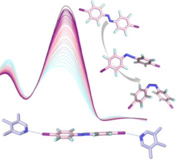
- photochemical properties upon introducing the heavy iodine to the azobenzene building block, as well as the effect of the ethynyl group in case of A3 (Figure 2). Vertical electronic absorption spectra of the different azobenzenes were calculated at the TD-B3LYP/def2-TZVP level of theory including Grimme D3

Graphical Abstract

Scheme 1: a) Azobenzenes A1–3 employed in this study. b) U-shaped anthracene halogen bond acceptor bearing tw...

Figure 1: Electrostatic potential map at different isodensity values (B3LYP/ def2/TZVP/DGZVP optimized geomet...

Figure 2: Top: Vertical electronic absorption spectra of a) A2 and b) A3, calculated using TD-B3LYP/def2-TZVP...

Figure 3: a) Space-filling model of U1···A2. The kinked alignment of both the lutidine units of U1 and the az...
Norbornadiene-functionalized triazatriangulenium and trioxatriangulenium platforms
- Roland Löw,
- Talina Rusch,
- Tobias Moje,
- Fynn Röhricht,
- Olaf M. Magnussen and
- Rainer Herges
Beilstein J. Org. Chem. 2019, 15, 1815–1821, doi:10.3762/bjoc.15.175

- monolayers. A linear, π-conjugated spacer (e.g., an ethynyl unit) is attached to the central carbon atom and the functional molecule is mounted on top. This architecture allows investigating molecules on surfaces under controlled conditions. The size of the platforms determines the intermolecular distances
- parameter controlling the cis–trans rate acceleration of azobenzenes and not the length of the spacer [1]. A full conjugation path from the azobenzene on top through the ethynyl spacer and the platform to a bulk gold surface shortens the half-life of the metastable cis-isomer from days to seconds even
- of a triplet sensitizer, mediate the spin change (which otherwise is forbidden) and accelerate the cycloreversion. Substitution in the 2 and 3 positions shifts the bathochromic absorption to 375 nm which is in agreement with similar systems [8]. Furthermore, the cyano and ethynyl groups provide a

Graphical Abstract

Figure 1: Structures of the norbornadiene platform 1a and the quadricyclane platform 1b (for geometry coordin...

Scheme 1: Syntheses of the norbornadiene TATA platform 1 and TOTA platform 3. a) TMS-acetylene, Pd(PPh3)4, Cu...

Scheme 2: Synthesis of methylphenylnorbornadiene platform 2. a) Pd(PPh3)4, Na2CO3, toluene, EtOH, H2O, N2, re...

Figure 2: UV–vis spectra of platform molecules 1 (a), 2 (b) and 3 (c) (in THF at rt): Norbornadiene (black), ...

Figure 3: 1H NMR spectra of 1 in deuterated oxygen containing deuterated benzene (left) and degassed deuterat...

Figure 4: Determination of the thermal isomerization rate k of 1b (QC) by 1H NMR spectroscopy (toluene, 293.5...

Figure 5: (a) STM image of self-assembled monolayers of compound 1 on Au(111) (40 × 40 nm2, It = 0.05 nA, Ubi...
Synthesis, enantioseparation and photophysical properties of planar-chiral pillar[5]arene derivatives bearing fluorophore fragments
- Guojuan Li,
- Chunying Fan,
- Guo Cheng,
- Wanhua Wu and
- Cheng Yang
Beilstein J. Org. Chem. 2019, 15, 1601–1611, doi:10.3762/bjoc.15.164

- derivatives P5A-Py was synthesized by following our previously reported processes [34], and P5A-DPA was synthesized by the processes illustrated in Scheme 1. The ethynyl-bearing pillar[5]arene derivative P5A was obtained through the co-cyclization of 4.0 equiv of 1,4-dimethoxybenzene with 1.0 equiv of the

Graphical Abstract

Scheme 1: Preparation of A1/A2-difunctionalized pillar[5]arenes (P5A-DPA and P5A-Py) by click reactions. Reag...

Figure 1: UV–vis absorption (a) and fluorescence emission spectra (b) of Py-6, P5A-Py (λex = 420 nm) and DPA-6...

Figure 2: (a) Fluorescence decay curves of Py-6 and P5A-Py at 450 nm and (b) fluorescence decay curves of DPA...

Figure 3: (a) Chiral HPLC traces of P5A-DPA, (b), (c) the first and second fractions of P5A-DPA, detected by ...

Figure 4: (a) CD, (b) UV–vis and (c) fluorescence spectra of the RP5A-DPA (20 μM) in THF and THF/H2O solvent ...
Diazocine-functionalized TATA platforms
- Roland Löw,
- Talina Rusch,
- Fynn Röhricht,
- Olaf Magnussen and
- Rainer Herges
Beilstein J. Org. Chem. 2019, 15, 1485–1490, doi:10.3762/bjoc.15.150

- ” (triazatriangulenium) platforms which adsorb on Au(111) surfaces. A spacer, such as an ethynyl group is connected to the central carbon atom like a post and the azobenzene is mounted on top of the spacer. After preparation of an ordered self-assembled monolayer on gold, the azobenzene units are freestanding upright on
- that are more stable in their trans-configurations [23]. To investigate the electronic coupling effects, we synthesized two diazocine derivatized TATA platforms with ethynyl spacers (diazocine-TATAs). In compound 1 the diazocine is connected to the platform with the ethynyl group in para-position to
- the azo group, providing a full π-conjugation path of the N=N unit through the ethynyl spacer into the platform. Diazocine-TATA 2 is connected in meta-position and thus interrupting conjugation [24][25]. Both diazocine-TATAs are equipped with methoxy groups, which serve as “reporter units” indicating

Graphical Abstract

Figure 1: Structures of diazocine platform molecules (diazocine-TATAs) 1 and 2 in cis (1a, 2a) and trans-conf...

Scheme 1: Synthesis route of para-diazocine platform molecule 1. a) Pd(dppf)Cl2, Cu(I)I, Et3N, 1 h, 60 °C; b)...

Scheme 2: Synthesis route of meta-diazocine platform 2. a) 1: KOt-Bu, THF, 3 min, 0 °C, N2; 2: Br2, 5 min, 0 ...

Figure 2: UV–vis spectra of 1 (left) and 2 (right) in THF at room temperature. Black: as synthesized, red: af...

Figure 3: STM images (30 × 30 nm², Ubias = 0.3 V, It = 40 pA) of self-assembled monolayers of (a) compound 1 ...
Borylation and rearrangement of alkynyloxiranes: a stereospecific route to substituted α-enynes
- Ruben Pomar Fuentespina,
- José Angel Garcia de la Cruz,
- Gabriel Durin,
- Victor Mamane,
- Jean-Marc Weibel and
- Patrick Pale
Beilstein J. Org. Chem. 2019, 15, 1416–1424, doi:10.3762/bjoc.15.141

- challenge in organic chemistry. Results and Discussion Reaction set up First we selected the simple 2-ethynyl-3-dimethyloxirane 1a to probe the feasibility of the reaction. In order to avoid unwanted reactions upon metalation [23], the ethynyl group was silylated and a bulky silyl group was installed to

Graphical Abstract

Scheme 1: Stereospecific formation of α-enynes from alkynyloxiranes.

Scheme 2: Trapping experiments of the oxiranyllithium derived from cis or trans-alkynyloxiranes 1b, and their...

Scheme 3: Proposed mechanism for the rearrangement of alkynyloxiranes to α-enynes through metalation and bory...
Synthesis of dipolar molecular rotors as linkers for metal-organic frameworks
- Sebastian Hamer,
- Fynn Röhricht,
- Marius Jakoby,
- Ian A. Howard,
- Xianghui Zhang,
- Christian Näther and
- Rainer Herges
Beilstein J. Org. Chem. 2019, 15, 1331–1338, doi:10.3762/bjoc.15.132

- molecules. Four rotors are fluorescent in the visible region. The linker designs are based on push–pull-substituted phenylene cores with ethynyl spacers as rotational axes, functionalized with carboxylic acid groups for implementation in MOFs. The substituents at the phenylene core are chosen to be small to
- is provided by ethynyl units as rotary joints. Carboxylate groups are terminating the axes on both sides because they are known to form the typical paddle wheel structures in MOFs [36]. Benzo-annelated 2,1,3-thiadiazoles were introduced (2 and 3) to shift absorption and fluorescence into the visible
- Müllen et al. [32] without compromising MOF compatibility by 4,5-diamino substitution. Synthesis of dipolar molecular rotor linkers The key step for the synthesis of all reported linkers is the coupling of a substituted aromatic core unit with two ethynyl substituents in para-orientation as spacer units

Graphical Abstract

Figure 1: Interactions of a pair of dipolar rotors in different orientations. The axes of the rotors are para...

Figure 2: Structures of molecular dipolar rotors/linker molecules 1–5.

Scheme 1: General synthetic strategy to prepare the dipolar rotors 1–5.

Scheme 2: Synthesis of 3,3'-(2,3-difluoro-1,4-phenylene)dipropiolic acid (1) starting with diiodination of 1,...

Scheme 3: Synthesis of 3,3'-(5,6-Difluoro-2,1,3-benzothiadiazol-4,7-diyl)dipropiolic acid (2) and 3,3'-(5,6-D...

Scheme 4: Synthesis of 3,3'-(5,6-dicyano-1,3-benzodioxole-4,7-diyl)dipropiolic acid (4) and 3,3'-(6,7-dicyano...
Remarkable effect of alkynyl substituents on the fluorescence properties of a BN-phenanthrene
- Alberto Abengózar,
- David Sucunza,
- Patricia García-García and
- Juan J. Vaquero
Beilstein J. Org. Chem. 2019, 15, 1257–1261, doi:10.3762/bjoc.15.122

- fluorescence quantum yield of BN-phenanthrene seems to be a general effect, irrespective of its position. It should be noted that the introduction of ethynyl groups into the all-carbon phenanthrene skeleton results in a slight increase in the fluorescence quantum yields compared to that of phenanthrene [27

Graphical Abstract

Figure 1: BN-phenanthrene 1a and synthesis of substituted derivatives proposed in this work.

Scheme 1: Synthesis of Cl-substituted BN-phenanthrene 1b.

Scheme 2: Palladium-catalyzed cross-couplings of Cl-substituted BN-phenanthrene 1b.

Scheme 3: Pd-catalyzed Sonogashira reactions of Cl-substituted BN-phenanthrene 1b.

Figure 2: UV–vis absorption (top) and emission (bottom) spectra for BN-phenanthrenes 1 and 5 in cyclohexane (...

Figure 3: Solutions of 1a–f and 5 (from left to right) under UV irradiation.
Stereo- and regioselective hydroboration of 1-exo-methylene pyranoses: discovery of aryltriazolylmethyl C-galactopyranosides as selective galectin-1 inhibitors
- Alexander Dahlqvist,
- Axel Furevi,
- Niklas Warlin,
- Hakon Leffler and
- Ulf J. Nilsson
Beilstein J. Org. Chem. 2019, 15, 1046–1060, doi:10.3762/bjoc.15.102

- mesyl chloride in pyridine at 0 °C to give 2-deoxy-1-mesylgalactoheptulose 8 (91%), followed by a nucleophilic substitution reaction with sodium azide in dimethylformamide to give the azide 9 in good yield (90%) [26]. The azide 9 was reacted with a panel of substituted ethynyl arenes to give
- -Tetra-O-benzyl-1,2-dideoxy-1-[4-(4-fluorophenyl)-1H-1,2,3-triazol-1-yl]-β-D-galactoheptulose (10b): Compound 9 (113 mg, 0.198 mmol), 1-ethynyl-4-fluorobenzene (29 mg, 0.238 mmol), and copper(I) iodide (4 mg, 0.035 mmol) were dissolved in dry acetonitrile (3 mL) under nitrogen, triethylamine (55 μL,0.397
- -galactoheptulose (10c): Compound 9 (107 mg, 0.185 mmol) and copper(I) iodide (4 mg, 0.035 mmol) were dissolved in dry acetonitrile (3 mL) under nitrogen, triethylamine (51 μL (0.369 mmol) and 1-ethynyl-3-fluorobenzene (26 μL, 0.221 mmol) were added, and the reaction was left at room temperature overnight. Upon

Graphical Abstract

Scheme 1: Diastereoselective hydroboration of glycopyranosyl exomethylene enol ethers 2, 4, and 6: a) BH3-DMS...

Scheme 2: Synthesis of (aryltriazolyl)methylene galactopyranosides 1a–n. Conditions: a) 3, MsCl, pyridine, 0 ...

Figure 1: Galectin-1 in complex with 1b derived by energy-minimizing a representative snapshot from a 200 ns ...