Green chemistry II

Università degli Studi di Perugia
Green chemistry is attracting increasing attention from many scientific areas proving that the development of a sustainable civilization is a common goal that can stem from numerous approaches
Within this context, chemistry certainly plays a crucial role in the design and implementation of innovative processes aimed at increasing the competitiveness and the efficiency of a modern chemical production. Organic chemistry in particular, is a pivotal research area able to contribute to the development of green chemistry in many different aspects: identification and manipulation of novel materials deriving from renewable resources, innovative and sustainable catalytic systems able to optimize known processes or access new chemical transformations, novel technologies able to increase the energy efficiency of the organic synthesis (e.g. microwave or ultrasounds irradiations, flow chemistry, …), definition of highly productive multicomponent processes, identification of new safer alternatives to replace toxic solvents. These are just some examples of the green chemistry toolbox and in this thematic issue we aim to collect original research and review articles dealing with the multidisciplinary and broad field of green organic chemistry.
Safe and highly efficient adaptation of potentially explosive azide chemistry involved in the synthesis of Tamiflu using continuous-flow technology
- Cloudius R. Sagandira and
- Paul Watts
Beilstein J. Org. Chem. 2019, 15, 2577–2589, doi:10.3762/bjoc.15.251


Palladium-catalyzed Sonogashira coupling reactions in γ-valerolactone-based ionic liquids
- László Orha,
- József M. Tukacs,
- László Kollár and
- László T. Mika
Beilstein J. Org. Chem. 2019, 15, 2907–2913, doi:10.3762/bjoc.15.284


A green, economical synthesis of β-ketonitriles and trifunctionalized building blocks from esters and lactones
- Daniel P. Pienaar,
- Kamogelo R. Butsi,
- Amanda L. Rousseau and
- Dean Brady
Beilstein J. Org. Chem. 2019, 15, 2930–2935, doi:10.3762/bjoc.15.287


Oligomeric ricinoleic acid preparation promoted by an efficient and recoverable Brønsted acidic ionic liquid
- Fei You,
- Xing He,
- Song Gao,
- Hong-Ru Li and
- Liang-Nian He
Beilstein J. Org. Chem. 2020, 16, 351–361, doi:10.3762/bjoc.16.34


Suzuki–Miyaura cross coupling is not an informative reaction to demonstrate the performance of new solvents
- James Sherwood
Beilstein J. Org. Chem. 2020, 16, 1001–1005, doi:10.3762/bjoc.16.89


The charge-assisted hydrogen-bonded organic framework (CAHOF) self-assembled from the conjugated acid of tetrakis(4-aminophenyl)methane and 2,6-naphthalenedisulfonate as a new class of recyclable Brønsted acid catalysts
- Svetlana A. Kuznetsova,
- Alexander S. Gak,
- Yulia V. Nelyubina,
- Vladimir A. Larionov,
- Han Li,
- Michael North,
- Vladimir P. Zhereb,
- Alexander F. Smol'yakov,
- Artem O. Dmitrienko,
- Michael G. Medvedev,
- Igor S. Gerasimov,
- Ashot S. Saghyan and
- Yuri N. Belokon
Beilstein J. Org. Chem. 2020, 16, 1124–1134, doi:10.3762/bjoc.16.99


Synthesis of pyrrolidinedione-fused hexahydropyrrolo[2,1-a]isoquinolines via three-component [3 + 2] cycloaddition followed by one-pot N-allylation and intramolecular Heck reactions
- Xiaoming Ma,
- Suzhi Meng,
- Xiaofeng Zhang,
- Qiang Zhang,
- Shenghu Yan,
- Yue Zhang and
- Wei Zhang
Beilstein J. Org. Chem. 2020, 16, 1225–1233, doi:10.3762/bjoc.16.106


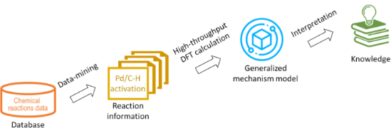
In silico rationalisation of selectivity and reactivity in Pd-catalysed C–H activation reactions
- Liwei Cao,
- Mikhail Kabeshov,
- Steven V. Ley and
- Alexei A. Lapkin
Beilstein J. Org. Chem. 2020, 16, 1465–1475, doi:10.3762/bjoc.16.122


Mechanochemical green synthesis of hyper-crosslinked cyclodextrin polymers
- Alberto Rubin Pedrazzo,
- Fabrizio Caldera,
- Marco Zanetti,
- Silvia Lucia Appleton,
- Nilesh Kumar Dhakar and
- Francesco Trotta
Beilstein J. Org. Chem. 2020, 16, 1554–1563, doi:10.3762/bjoc.16.127


One-pot synthesis of isosorbide from cellulose or lignocellulosic biomass: a challenge?
- Isaline Bonnin,
- Raphaël Mereau,
- Thierry Tassaing and
- Karine De Oliveira Vigier
Beilstein J. Org. Chem. 2020, 16, 1713–1721, doi:10.3762/bjoc.16.143


Natural dolomitic limestone-catalyzed synthesis of benzimidazoles, dihydropyrimidinones, and highly substituted pyridines under ultrasound irradiation
- Kumar Godugu,
- Venkata Divya Sri Yadala,
- Mohammad Khaja Mohinuddin Pinjari,
- Trivikram Reddy Gundala,
- Lakshmi Reddy Sanapareddy and
- Chinna Gangi Reddy Nallagondu
Beilstein J. Org. Chem. 2020, 16, 1881–1900, doi:10.3762/bjoc.16.156


Regiodivergent synthesis of functionalized pyrimidines and imidazoles through phenacyl azides in deep eutectic solvents
- Paola Vitale,
- Luciana Cicco,
- Ilaria Cellamare,
- Filippo M. Perna,
- Antonio Salomone and
- Vito Capriati
Beilstein J. Org. Chem. 2020, 16, 1915–1923, doi:10.3762/bjoc.16.158


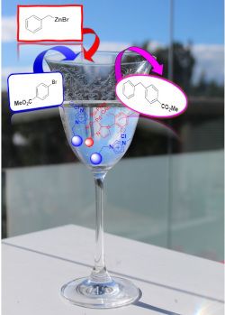
Synergy between supported ionic liquid-like phases and immobilized palladium N-heterocyclic carbene–phosphine complexes for the Negishi reaction under flow conditions
- Edgar Peris,
- Raúl Porcar,
- María Macia,
- Jesús Alcázar,
- Eduardo García-Verdugo and
- Santiago V. Luis
Beilstein J. Org. Chem. 2020, 16, 1924–1935, doi:10.3762/bjoc.16.159


A proposed sustainability index for synthesis plans based on input provenance and output fate: application to academic and industrial synthesis plans for vanillin as a case study
- John Andraos
Beilstein J. Org. Chem. 2020, 16, 2346–2362, doi:10.3762/bjoc.16.196


Palladium nanoparticles supported on chitin-based nanomaterials as heterogeneous catalysts for the Heck coupling reaction
- Tony Jin,
- Malickah Hicks,
- Davis Kurdyla,
- Sabahudin Hrapovic,
- Edmond Lam and
- Audrey Moores
Beilstein J. Org. Chem. 2020, 16, 2477–2483, doi:10.3762/bjoc.16.201


One-pot multicomponent green Hantzsch synthesis of 1,2-dihydropyridine derivatives with antiproliferative activity
- Giovanna Bosica,
- Kaylie Demanuele,
- José M. Padrón and
- Adrián Puerta
Beilstein J. Org. Chem. 2020, 16, 2862–2869, doi:10.3762/bjoc.16.235


A novel and robust heterogeneous Cu catalyst using modified lignosulfonate as support for the synthesis of nitrogen-containing heterocycles
- Bingbing Lai,
- Meng Ye,
- Ping Liu,
- Minghao Li,
- Rongxian Bai and
- Yanlong Gu
Beilstein J. Org. Chem. 2020, 16, 2888–2902, doi:10.3762/bjoc.16.238


Three-component reactions of aromatic amines, 1,3-dicarbonyl compounds, and α-bromoacetaldehyde acetal to access N-(hetero)aryl-4,5-unsubstituted pyrroles
- Wenbo Huang,
- Kaimei Wang,
- Ping Liu,
- Minghao Li,
- Shaoyong Ke and
- Yanlong Gu
Beilstein J. Org. Chem. 2020, 16, 2920–2928, doi:10.3762/bjoc.16.241


Ultrasound-assisted Strecker synthesis of novel 2-(hetero)aryl-2-(arylamino)acetonitrile derivatives
- Emese Gal,
- Luiza Gaina,
- Hermina Petkes,
- Alexandra Pop,
- Castelia Cristea,
- Gabriel Barta,
- Dan Cristian Vodnar and
- Luminiţa Silaghi-Dumitrescu
Beilstein J. Org. Chem. 2020, 16, 2929–2936, doi:10.3762/bjoc.16.242


Metal-free synthesis of biarenes via photoextrusion in di(tri)aryl phosphates
- Hisham Qrareya,
- Lorenzo Meazza,
- Stefano Protti and
- Maurizio Fagnoni
Beilstein J. Org. Chem. 2020, 16, 3008–3014, doi:10.3762/bjoc.16.250


An atom-economical addition of methyl azaarenes with aromatic aldehydes via benzylic C(sp3)–H bond functionalization under solvent- and catalyst-free conditions
- Divya Rohini Yennamaneni,
- Vasu Amrutham,
- Krishna Sai Gajula,
- Rammurthy Banothu,
- Murali Boosa and
- Narender Nama
Beilstein J. Org. Chem. 2020, 16, 3093–3103, doi:10.3762/bjoc.16.259


A sustainable strategy for the straightforward preparation of 2H-azirines and highly functionalized NH-aziridines from vinyl azides using a single solvent flow-batch approach
- Michael Andresini,
- Leonardo Degannaro and
- Renzo Luisi
Beilstein J. Org. Chem. 2021, 17, 203–209, doi:10.3762/bjoc.17.20


Deoxygenative C2-heteroarylation of quinoline N-oxides: facile access to α-triazolylquinolines
- Geetanjali S. Sontakke,
- Rahul K. Shukla and
- Chandra M. R. Volla
Beilstein J. Org. Chem. 2021, 17, 485–493, doi:10.3762/bjoc.17.42


Designed whole-cell-catalysis-assisted synthesis of 9,11-secosterols
- Marek Kõllo,
- Marje Kasari,
- Villu Kasari,
- Tõnis Pehk,
- Ivar Järving,
- Margus Lopp,
- Arvi Jõers and
- Tõnis Kanger
Beilstein J. Org. Chem. 2021, 17, 581–588, doi:10.3762/bjoc.17.52


Valorisation of plastic waste via metal-catalysed depolymerisation
- Francesca Liguori,
- Carmen Moreno-Marrodán and
- Pierluigi Barbaro
Beilstein J. Org. Chem. 2021, 17, 589–621, doi:10.3762/bjoc.17.53


Synthesis of β-triazolylenones via metal-free desulfonylative alkylation of N-tosyl-1,2,3-triazoles
- Soumyaranjan Pati,
- Renata G. Almeida,
- Eufrânio N. da Silva Júnior and
- Irishi N. N. Namboothiri
Beilstein J. Org. Chem. 2021, 17, 762–770, doi:10.3762/bjoc.17.66


Nitroalkene reduction in deep eutectic solvents promoted by BH3NH3
- Chiara Faverio,
- Monica Fiorenza Boselli,
- Patricia Camarero Gonzalez,
- Alessandra Puglisi and
- Maurizio Benaglia
Beilstein J. Org. Chem. 2021, 17, 1041–1047, doi:10.3762/bjoc.17.83


