Search results
Search for "metals" in Full Text gives 492 result(s) in Beilstein Journal of Organic Chemistry. Showing first 200.
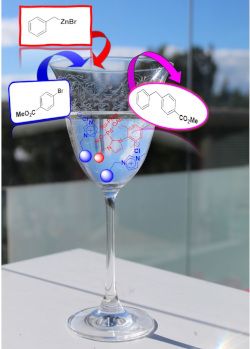
A new and efficient methodology for olefin epoxidation catalyzed by supported cobalt nanoparticles
- Lucía Rossi-Fernández,
- Viviana Dorn and
- Gabriel Radivoy
Beilstein J. Org. Chem. 2021, 17, 519–526, doi:10.3762/bjoc.17.46

- have been developed, most of them using expensive or scarce metals (Au or Pd [18][19][20][21], groups IV and V metal oxides [22][23]) and mainly through homogeneous catalytic processes [24][25][26]. From a practical, economic and environmental point of view, reusable heterogeneous catalysts based on
- earth-abundant transition metals are much more attractive, especially for industrial applications [27][28]. In recent years, many efforts have been made in finding new catalytic systems based on the use of low cost and abundant non-noble metals, and much attention have been paid to the development of Fe
- , Mn and mainly Co-based catalysts for olefin epoxidation. Besides their low cost and low toxicity, the choice of these metals is related to their known ability to activate dioxygen in natural processes catalyzed by metal-containing enzymes [29][30]. Despite that various homogeneous [31][32] and

Graphical Abstract

Figure 1: TEM micrograph and size distribution graphic for CoNPs@MgO catalyst (scale bar = 20 nm).

Scheme 1: Plausible mechanistic pathway for olefin epoxidation catalyzed by CoNPs/MgO in the presence of t-Bu...
Annulation of a 1,3-dithiole ring to a sterically hindered o-quinone core. Novel ditopic redox-active ligands
- Sergey V. Norkov,
- Anton V. Cherkasov,
- Andrey S. Shavyrin,
- Maxim V. Arsenyev,
- Viacheslav A. Kuropatov and
- Vladimir K. Cherkasov
Beilstein J. Org. Chem. 2021, 17, 273–282, doi:10.3762/bjoc.17.26

- coordination ability. The redox state of o-quinone (semiquinone or catechol) could be changed both as free species or when it is coordinated to a metal ion as a ligand. Thus, the redox isomerism phenomenon was reported for o-quinone complexes with both transition and non-transition metals [1][2][3]. The
- ). The values of coupling constants with these protons vary in the range of 0.18–0.30 G, they are highly sensitive to the nature of the metallofragment at the chelating dioxolene site. With metals tending to high ionicity in the bonding with the ligand we observed smaller values of coupling constants. o
- and CF3 groups are omitted for clarity. Synthetic pathways for the preparation of o-quinone derivatives with annulated 1,3-dithiole ring. The tentative pathway for the formation of o-quinone 7 with annulated thiete ring. Reactions of o-quinone 6a. Stepwise reduction of o-quinones with metals to

Graphical Abstract

Scheme 1: Synthetic pathways for the preparation of o-quinone derivatives with annulated 1,3-dithiole ring.

Figure 1: Active methylene compounds used for the preparation of gem-dithiolates.

Figure 2: Fragment of coordination polymer chain of adduct 8 in the crystal phase. Hydrogen atoms and CF3 gro...

Scheme 2: The tentative pathway for the formation of o-quinone 7 with annulated thiete ring.

Scheme 3: Reactions of o-quinone 6a.

Scheme 4: Stepwise reduction of o-quinones with metals to semiquinonates and catecholates, respectively.
The preparation and properties of 1,1-difluorocyclopropane derivatives
- Kymbat S. Adekenova,
- Peter B. Wyatt and
- Sergazy M. Adekenov
Beilstein J. Org. Chem. 2021, 17, 245–272, doi:10.3762/bjoc.17.25

- -valent transition metals such as Pd(0) also have a valuable catalytic role, particularly because of their ability to participate in oxidative addition reactions and to form π-allyl complexes. In the absence of nucleophiles, homolysis of the distal C–C bond takes place under the effect of high temperature

Graphical Abstract

Scheme 1: Synthesis of 1,1-difluoro-2,3-dimethylcyclopropane (2).

Scheme 2: Cyclopropanation via dehydrohalogenation of chlorodifluoromethane.

Scheme 3: Difluorocyclopropanation of methylstyrene 7 using dibromodifluoromethane and zinc.

Scheme 4: Synthesis of difluorocyclopropanes from the reaction of dibromodifluoromethane and triphenylphosphi...

Scheme 5: Generation of difluorocarbene in a catalytic two-phase system and its addition to tetramethylethyle...

Scheme 6: The reaction of methylstyrene 7 with chlorodifluoromethane (11) in the presence of a tetraarylarson...

Scheme 7: Pyrolysis of sodium chlorodifluoroacetate (12) in refluxing diglyme in the presence of alkene 13.

Scheme 8: Synthesis of boron-substituted gem-difluorocyclopropanes 16.

Scheme 9: Addition of sodium bromodifluoroacetate (17) to alkenes.

Scheme 10: Addition of sodium bromodifluoroacetate (17) to silyloxy-substituted cyclopropanes 20.

Scheme 11: Synthesis of difluorinated nucleosides.

Scheme 12: Addition of butyl acrylate (26) to difluorocarbene generated from TFDA (25).

Scheme 13: Addition of difluorocarbene to propargyl esters 27 and conversion of the difluorocyclopropenes 28 t...

Scheme 14: The generation of difluorocyclopropanes using MDFA 30.

Scheme 15: gem-Difluorocyclopropanation of styrene (32) using difluorocarbene generated from TMSCF3 (31) under...

Scheme 16: Synthesis of a gem-difluorocyclopropane derivative using HFPO (41) as a source of difluorocarbene.

Scheme 17: Cyclopropanation of (Z)-2-butene in the presence of difluorodiazirine (44).

Scheme 18: The cyclopropanation of 1-octene (46) using Seyferth's reagent (45) as a source of difluorocarbene.

Scheme 19: Alternative approaches for the difluorocarbene synthesis from trimethyl(trifluoromethyl)tin (48).

Scheme 20: Difluorocyclopropanation of cyclohexene (49).

Scheme 21: Synthesis of difluorocyclopropane derivative 53 using bis(trifluoromethyl)cadmium (51) as the diflu...

Scheme 22: Addition of difluorocarbene generated from tris(trifluoromethyl)bismuth (54).

Scheme 23: Addition of a stable (trifluoromethyl)zinc reagent to styrenes.

Scheme 24: The preparation of 2,2-difluorocyclopropanecarboxylic acids of type 58.

Scheme 25: Difluorocyclopropanation via Michael cyclization.

Scheme 26: Difluorocyclopropanation using N-acylimidazolidinone 60.

Scheme 27: Difluorocyclopropanation through the cyclization of phenylacetonitrile (61) and 1,2-dibromo-1,1-dif...

Scheme 28: gem-Difluoroolefins 64 for the synthesis of functionalized cyclopropanes 65.

Scheme 29: Preparation of aminocyclopropanes 70.

Scheme 30: Synthesis of fluorinated methylenecyclopropane 74 via selenoxide elimination.

Scheme 31: Reductive dehalogenation of (1R,3R)-75.

Scheme 32: Synthesis of chiral monoacetates by lipase catalysis.

Scheme 33: Transformation of (±)-trans-81 using Rhodococcus sp. AJ270.

Scheme 34: Transformation of (±)-trans-83 using Rhodococcus sp. AJ270.

Scheme 35: Hydrogenation of difluorocyclopropenes through enantioselective hydrocupration.

Scheme 36: Enantioselective transfer hydrogenation of difluorocyclopropenes with a Ru-based catalyst.

Scheme 37: The thermal transformation of trans-1,2-dichloro-3,3-difluorocyclopropane (84).

Scheme 38: cis–trans-Epimerization of 1,1-difluoro-2,3-dimethylcyclopropane.

Scheme 39: 2,2-Difluorotrimethylene diradical intermediate.

Scheme 40: Ring opening of stereoisomers 88 and 89.

Scheme 41: [1,3]-Rearrangement of alkenylcyclopropanes 90–92.

Scheme 42: Thermolytic rearrangement of 2,2-difluoro-1-vinylcyclopropane (90).

Scheme 43: Thermal rearrangement for ethyl 3-(2,2-difluoro)-3-phenylcyclopropyl)acrylates 93 and 95.

Scheme 44: Possible pathways of the ring opening of 1,1-difluoro-2-vinylcyclopropane.

Scheme 45: Equilibrium between 1,1-difluoro-2-methylenecyclopropane (96) and (difluoromethylene)cyclopropane 97...

Scheme 46: Ring opening of substituted 1,1-difluoro-2,2-dimethyl-3-methylenecyclopropane 98.

Scheme 47: 1,1-Difluorospiropentane rearrangement.

Scheme 48: Acetolysis of (2,2-difluorocyclopropyl)methyl tosylate (104) and (1,1-difluoro-2-methylcyclopropyl)...

Scheme 49: Ring opening of gem-difluorocyclopropyl ketones 106 and 108 by thiolate nucleophiles.

Scheme 50: Hydrolysis of gem-difluorocyclopropyl acetals 110.

Scheme 51: Ring-opening reaction of 2,2-difluorocyclopropyl ketones 113 in the presence of ionic liquid as a s...

Scheme 52: Ring opening of gem-difluorocyclopropyl ketones 113a by MgI2-initiated reaction with diarylimines 1...

Scheme 53: Ring-opening reaction of gem-difluorocyclopropylstannanes 117.

Scheme 54: Preparation of 1-fluorovinyl vinyl ketone 123 and the synthesis of 2-fluorocyclopentenone 124. TBAT...

Scheme 55: Iodine atom-transfer ring opening of 1,1-difluoro-2-(1-iodoalkyl)cyclopropanes 125a–c.

Scheme 56: Ring opening of bromomethyl gem-difluorocyclopropanes 130 and formation of gem-difluoromethylene-co...

Scheme 57: Ring-opening aerobic oxidation reaction of gem-difluorocyclopropanes 132.

Scheme 58: Dibrominative ring-opening functionalization of gem-difluorocyclopropanes 134.

Scheme 59: The selective formation of (E,E)- and (E,Z)-fluorodienals 136 and 137 from difluorocyclopropyl acet...

Scheme 60: Proposed mechanism for the reaction of difluoro(methylene)cyclopropane 139 with Br2.

Scheme 61: Thermal rearrangement of F2MCP 139 and iodine by CuI catalysis.

Scheme 62: Synthesis of 2-fluoropyrroles 142.

Scheme 63: Ring opening of gem-difluorocyclopropyl ketones 143 mediated by BX3.

Scheme 64: Lewis acid-promoted ring-opening reaction of 2,2-difluorocyclopropanecarbonyl chloride (148).

Scheme 65: Ring-opening reaction of the gem-difluorocyclopropyl ketone 106 by methanolic KOH.

Scheme 66: Hydrogenolysis of 1,1-difluoro-3-methyl-2-phenylcyclopropane (151).

Scheme 67: Synthesis of monofluoroalkenes 157.

Scheme 68: The stereoselective Ag-catalyzed defluorinative ring-opening diarylation of 1-trimethylsiloxy-2,2-d...

Scheme 69: Synthesis of 2-fluorinated allylic compounds 162.

Scheme 70: Pd-catalyzed cross-coupling reactions of gem-difluorinated cyclopropanes 161.

Scheme 71: The (Z)-selective Pd-catalyzed ring-opening sulfonylation of 2-(2,2-difluorocyclopropyl)naphthalene...

Figure 1: Structures of zosuquidar hydrochloride and PF-06700841.

Scheme 72: Synthesis of methylene-gem-difluorocyclopropane analogs of nucleosides.

Figure 2: Anthracene-difluorocyclopropane hybrid derivatives.

Figure 3: Further examples of difluorcyclopropanes in modern drug discovery.
Selective synthesis of α-organylthio esters and α-organylthio ketones from β-keto esters and sodium S-organyl sulfurothioates under basic conditions
- Jean C. Kazmierczak,
- Roberta Cargnelutti,
- Thiago Barcellos,
- Claudio C. Silveira and
- Ricardo F. Schumacher
Beilstein J. Org. Chem. 2021, 17, 234–244, doi:10.3762/bjoc.17.24

- , and related compounds. Some of them are catalyzed by expensive transition metals, such as gold, iridium, palladium, and titanium. More recently, the selective formation of C–S bonds using 1,3-dicarbonyl compounds, followed by a C–C bond cleavage has emerged as a versatile and less expensive protocol

Graphical Abstract

Figure 1: Drugs and agrochemicals containing the α-thiocarbonyl core as a structural motif.

Scheme 1: Methods for the synthesis of α-thiocarbonyl compounds by C–C bond cleavage of 1,3-dicarbonyl compou...

Scheme 2: Formation of the enol 6 from acetylacetone (5).

Scheme 3: Formation of thio-substituted keto–enol tautomers 7 and 8.

Scheme 4: Proposed mechanism for the synthesis of 3.

Scheme 5: A tentative pathway for the synthesis of 4.
Au(III) complexes with tetradentate-cyclam-based ligands
- Ann Christin Reiersølmoen,
- Thomas N. Solvi and
- Anne Fiksdahl
Beilstein J. Org. Chem. 2021, 17, 186–192, doi:10.3762/bjoc.17.18

- range of other transition metals. The utilization of gold in synthetic organic chemistry has become a topic of interest during the last decades, as evidenced by the increasing number of review articles published in this period [1][2][3][4][5][6][7][8]. Whereas both gold(I) and gold(III) are proven to be
- binding properties [25] and reactions with bovine serum albumin [27]. Cyclam is known as a tetraamino-macrocyclic ligand, which binds strongly to give complexes with many transition metal cations. While catalytic applications of square planar cyclam complexes are reported for metals, such as Ni [30][31

Graphical Abstract

Scheme 1: Synthetic protocols for the preparation of potential ligands 1–4.

Scheme 2: Reduction of diamides 1a,b and tetraamides 2a,b.

Scheme 3: Au(III) coordination conditions for ligands 5a,b and 6a,b. Coordination of 5b was unsuccessful.

Figure 1: 1H NMR study of the formation of complex 6a-Au(III) by AuCl3 coordination to ligand 6a.
Insight into functionalized-macrocycles-guided supramolecular photocatalysis
- Minzan Zuo,
- Krishnasamy Velmurugan,
- Kaiya Wang,
- Xueqi Tian and
- Xiao-Yu Hu
Beilstein J. Org. Chem. 2021, 17, 139–155, doi:10.3762/bjoc.17.15

- a stabilizer to control the size and distribution of the NPs and are able to intensely regulate the photocatalytic performance. 5) To improve the sustainability, noble metals need to be replaced by earth-abundant metals. However, in most cases, earth-abundant metals have a lower photocatalytic
- activity compared to noble metals in supramolecular materials. Therefore, there is an urgent demand to search for earth-abundant metals with a high activity. In conclusion, investigations on macrocycle-based catalysis are still needed to effectively extend their potential applications to solve chemical

Graphical Abstract

Figure 1: Chemical structures of representative macrocycles.

Figure 2: Ba2+-induced intermolecular [2 + 2]-photocycloaddition of crown ether-functionalized substrates 1 a...

Figure 3: Energy transfer system constructed of a BODIPY–zinc porphyrin–crown ether triad assembly bound to a...

Figure 4: The sensitizer 5 was prepared by a flavin–zinc(II)–cyclen complex for the photooxidation of benzyl ...

Figure 5: Enantiodifferentiating Z–E photoisomerization of cyclooctene sensitized by a chiral sensitizer as t...

Figure 6: Structures of the modified CDs as chiral sensitizing hosts. Adapted with permission from [24], Copyrigh...

Figure 7: Supramolecular 1:1 and 2:2 complexations of AC with the cationic β-CD derivatives 16–21 and subsequ...

Figure 8: Construction of the TiO2–AuNCs@β-CD photocatalyst. Republished with permission of The Royal Society...

Figure 9: Visible-light-driven conversion of benzyl alcohol to H2 and a vicinal diol or to H2 and benzaldehyd...

Figure 10: (a) Structures of CDs, (b) CoPyS, and (c) EY. Republished with permission of The Royal Society of C...

Figure 11: Conversion of CO2 to CO by ReP/HO-TPA–TiO2. Republished with permission of The Royal Society of Che...

Figure 12: Thiacalix[4]arene-protected TiO2 clusters for H2 evolution. Reprinted with permission from [37], Copyri...

Figure 13: 4-Methoxycalix[7]arene film-based TiO2 photocatalytic system. Reprinted from [38], Materials Today Chem...

Figure 14: (a) Photodimerization of 6-methylcoumarin (22). (b) Catalytic cycle for the photodimerization of 22...

Figure 15: Formation of a supramolecular PDI–CB[7] complex and structures of monomers and the chain transfer a...

Figure 16: Ternary self-assembled system for photocatalytic H2 evolution (a) and structure of 27 (b). Figure 16 reprodu...

Figure 17: Structures of COP-1, CMP-1, and their substrate S-1 and S-2.

Figure 18: Supramolecular self-assembly of the light-harvesting system formed by WP5, β-CAR, and Chl-b. Reprod...

Figure 19: Photocyclodimerization of AC based on WP5 and WP6.
An atom-economical addition of methyl azaarenes with aromatic aldehydes via benzylic C(sp3)–H bond functionalization under solvent- and catalyst-free conditions
- Divya Rohini Yennamaneni,
- Vasu Amrutham,
- Krishna Sai Gajula,
- Rammurthy Banothu,
- Murali Boosa and
- Narender Nama
Beilstein J. Org. Chem. 2020, 16, 3093–3103, doi:10.3762/bjoc.16.259

- years, C−H bond functionalization catalyzed by transition metals received a strong emphasis, and other different catalytic systems have also been encouraged [16][17][18][19][20]. Huang and co-workers first realized the addition of alkylazaarenes directly to unsaturated bonds via C(sp3)–H
- , Yaragorla et al. published a review on C(sp3)–H bond functionalization of 2-methylazaarenes [39]. These strategies are proficient, but due to the involvement of drastic reaction conditions, the use of expensive reagents, toxic metals, harmful solvents, and tedious workup procedures, they need to be

Graphical Abstract

Scheme 1: Benzylic addition of aldehydes to azaarenes using different catalysts.

Scheme 2: Synthesis of azaarene derivatives from different precursors.

Scheme 3: Our work: catalyst- and solvent-free benzylic addition of aldehydes to azaarenes.

Scheme 4: Large-scale experiments for the synthesis of 2-(6-methylpyridin-2-yl)-1-(4-nitrophenyl)ethan-1-ol (...

Scheme 5: Plausible mechanism for the formation of 2-(6-methylpyridin-2-yl)-1-(4-nitrophenyl)ethan-1-ol (3a) ...
Controlled decomposition of SF6 by electrochemical reduction
- Sébastien Bouvet,
- Bruce Pégot,
- Stéphane Sengmany,
- Erwan Le Gall,
- Eric Léonel,
- Anne-Marie Goncalves and
- Emmanuel Magnier
Beilstein J. Org. Chem. 2020, 16, 2948–2953, doi:10.3762/bjoc.16.244

- reactive, corrosive and toxic [12]. Recent and really impressive works were devoted to the decomposition of sulfur hexafluoride using stoichiometric or catalytic amounts of metals (Rh, Ni, Pt) [13][14][15][16]. Organic derivatives (phosphines or bipyridine) proved efficient tools for the selective

Graphical Abstract

Figure 1: (a) Cyclic voltammetry onto microelectrode arrays (Ø = 20 µm) in acetonitrile freshly distilled aft...

Figure 2: Variation of the current reduction (i2) of SF6 onto Pt macroelectrode (Ø = 0.76 mm) at −2.3 V vs Fc+...

Figure 3: Single compartment three-electrode experiment. 1: Balloon of SF6, 2: electrochemical cell, 3: refer...

Figure 4: Electrolysis of SF6 at −2.3 V vs Fc+/Fc in acetonitrile freshly distilled after addition of TBAClO4...

Figure 5: 19F NMR evolution of the crude mixture along the time after electrolysis realized at constant poten...
Regioselective synthesis of heterocyclic N-sulfonyl amidines from heteroaromatic thioamides and sulfonyl azides
- Vladimir Ilkin,
- Vera Berseneva,
- Tetyana Beryozkina,
- Tatiana Glukhareva,
- Lidia Dianova,
- Wim Dehaen,
- Eugenia Seliverstova and
- Vasiliy Bakulev
Beilstein J. Org. Chem. 2020, 16, 2937–2947, doi:10.3762/bjoc.16.243

- synthesis of complexes of bis(sulfonyl amidines) 3aj–an with metals is in progress. 1H and 13C NMR spectra including 2D HMBC and HSQC experiments of compounds 3a–an, as well as high-resolution mass spectra are consistent with the proposed structures. Carbon signals of the amidine groups of compounds 3

Graphical Abstract

Figure 1: Examples of biological activity and interesting chemical reactivity of N-sulfonyl amidines.

Figure 2: Data on the synthesis of N′-sulfonylazole-4-carboximidamides.

Scheme 1: Synthesis of 1-alkyl-N-phenyl-N'-(sulfonyl)-1H-1,2,3-triazole-4-carboximidamides 3.

Figure 3: Starting compounds.

Scheme 2: Scope for the reaction of 1-alkyl-1,2,3-triazole-4-carbothioamides 1a–d with azides 2a–f.

Scheme 3: Scope of the reaction of 5-arylamino-1,2,3-triazole-4-carbothioamides 1i–l with azides 2a,c–f.

Scheme 4: Synthesis of 2-aminothiazole-4-N-sulfonyl amidines.

Scheme 5: Synthesis of N-sulfonyl amidines of isoxazolylcarboxylic acid.

Scheme 6: Synthesis of bis(sulfonyl amidines) 3aj–an.

Scheme 7: Plausible mechanism for the reaction of heterocyclic thioamides with sulfonyl azides.
A novel and robust heterogeneous Cu catalyst using modified lignosulfonate as support for the synthesis of nitrogen-containing heterocycles
- Bingbing Lai,
- Meng Ye,
- Ping Liu,
- Minghao Li,
- Rongxian Bai and
- Yanlong Gu
Beilstein J. Org. Chem. 2020, 16, 2888–2902, doi:10.3762/bjoc.16.238

- the catalyst during the recovery process (mass recovery 97.5%). In stark contrast, the two referential catalysts showed inferior recyclability (Figure 6b and 6c) not only because the mass loss but also the low stability and capacity of the metals. Conclusion A robust heterogeneous Cu catalyst was

Graphical Abstract

Figure 1: Schematic illustration for the preparation of the catalyst in this work.

Figure 2: FTIR spectra of LS, LS-FAS, and LS-FAS-Cu.

Figure 3: Thermogravimetric weight loss of the obtained materials LS-FAS and LS-FAS-Cu.

Figure 4: FSEM imagine of LS-FAS-Cu in different scale label a) 1 μm, b) 200 nm; FTEM images of LS-FAS-Cu in ...

Figure 5: XPS spectra of LS-FAS-Cu in the regions of C 1s, O 1s, Cu 2p3/2 and Cu LMM (inset).

Scheme 1: Substrate scope of LS-FAS-Cu catalyzed three-component reactions of 4-aminoindoles, alkynes and ald...

Figure 6: Recyclability of LS-FAS-Cu, LS-FM-Cu and Resin-Cu in the reaction between compounds 1a, 2a and 3a.
Dawn of a new era in industrial photochemistry: the scale-up of micro- and mesostructured photoreactors
- Emine Kayahan,
- Mathias Jacobs,
- Leen Braeken,
- Leen C.J. Thomassen,
- Simon Kuhn,
- Tom van Gerven and
- M. Enis Leblebici
Beilstein J. Org. Chem. 2020, 16, 2484–2504, doi:10.3762/bjoc.16.202


Graphical Abstract

Figure 1: The momentum transport affects the mass transfer and the light field. All transport phenomena need ...

Figure 2: Common photomicroreactor designs: (a) Straight channel, (b) serpentine channel, (c) square serpenti...

Figure 3: Benchmarked photoreactors: (a) Microcapillaries in parallel, (b) microcapillaries in series, (c) fl...

Figure 4: Photochemical reactions that are detailed in Table 1.

Figure 5: Structured reactors designed for enhancing the mass transfer: (a) Packed bed photoreactor, (b) mono...

Figure 6: Comparison of the LED board designs of photomicroreactors: (a) CC array design, (b) MC array design...

Figure 7: Illustration of the light scattering phenomenon inside a photocatalytic flow reactor.

Figure 8: Efficiency of the absorption process in scattering situations with respect to pure absorption situa...

Figure 9: Different types of distributors: (a) Traditional or consecutive manifold, (b) bifurcation unit dist...
Recent developments in enantioselective photocatalysis
- Callum Prentice,
- James Morrisson,
- Andrew D. Smith and
- Eli Zysman-Colman
Beilstein J. Org. Chem. 2020, 16, 2363–2441, doi:10.3762/bjoc.16.197


Graphical Abstract

Scheme 1: Amine/photoredox-catalysed α-alkylation of aldehydes with alkyl bromides bearing electron-withdrawi...

Scheme 2: Amine/HAT/photoredox-catalysed α-functionalisation of aldehydes using alkenes.

Scheme 3: Amine/cobalt/photoredox-catalysed α-functionalisation of ketones and THIQs.

Scheme 4: Amine/photoredox-catalysed α-functionalisation of aldehydes or ketones with imines. (a) Using keton...

Scheme 5: Bifunctional amine/photoredox-catalysed enantioselective α-functionalisation of aldehydes.

Scheme 6: Bifunctional amine/photoredox-catalysed α-functionalisation of aldehydes using amine catalysts via ...

Scheme 7: Amine/photoredox-catalysed RCA of iminium ion intermediates. (a) Synthesis of quaternary stereocent...

Scheme 8: Bifunctional amine/photoredox-catalysed RCA of enones in a radical chain reaction initiated by an i...

Scheme 9: Bifunctional amine/photoredox-catalysed RCA reactions of iminium ions with different radical precur...

Scheme 10: Bifunctional amine/photoredox-catalysed radical cascade reactions between enones and alkenes with a...

Scheme 11: Amine/photocatalysed photocycloadditions of iminium ion intermediates. (a) External photocatalyst u...

Scheme 12: Amine/photoredox-catalysed addition of acrolein (94) to iminium ions.

Scheme 13: Dual NHC/photoredox-catalysed acylation of THIQs.

Scheme 14: NHC/photocatalysed spirocyclisation via photoisomerisation of an extended Breslow intermediate.

Scheme 15: CPA/photoredox-catalysed aza-pinacol cyclisation.

Scheme 16: CPA/photoredox-catalysed Minisci-type reaction between azaarenes and α-amino radicals.

Scheme 17: CPA/photoredox-catalysed radical additions to azaarenes. (a) α-Amino radical or ketyl radical addit...

Scheme 18: CPA/photoredox-catalysed reduction of azaarene-derived substrates. (a) Reduction of ketones. (b) Ex...

Scheme 19: CPA/photoredox-catalysed radical coupling reactions of α-amino radicals with α-carbonyl radicals. (...

Scheme 20: CPA/photoredox-catalysed Povarov reaction.

Scheme 21: CPA/photoredox-catalysed reactions with imines. (a) Decarboxylative imine generation followed by Po...

Scheme 22: Bifunctional CPA/photocatalysed [2 + 2] photocycloadditions.

Scheme 23: PTC/photocatalysed oxygenation of 1-indanone-derived β-keto esters.

Scheme 24: PTC/photoredox-catalysed perfluoroalkylation of 1-indanone-derived β-keto esters via a radical chai...

Scheme 25: Bifunctional hydrogen bonding/photocatalysed intramolecular [2 + 2] photocycloadditions of quinolon...

Scheme 26: Bifunctional hydrogen bonding/photocatalysed intramolecular RCA cyclisation of a quinolone.

Scheme 27: Bifunctional hydrogen bonding/photocatalysed intramolecular [2 + 2] photocycloadditions of quinolon...

Scheme 28: Bifunctional hydrogen bonding/photocatalysed [2 + 2] photocycloaddition reactions. (a) First use of...

Scheme 29: Bifunctional hydrogen bonding/photocatalysed deracemisation of allenes.

Scheme 30: Bifunctional hydrogen bonding/photocatalysed deracemisation reactions. (a) Deracemisation of sulfox...

Scheme 31: Bifunctional hydrogen bonding/photocatalysed intramolecular [2 + 2] photocycloaddition of coumarins....

Scheme 32: Bifunctional hydrogen bonding/photocatalysed [2 + 2] photocycloadditions of quinolones. (a) Intramo...

Scheme 33: Hydrogen bonding/photocatalysed formal arylation of benzofuranones.

Scheme 34: Hydrogen bonding/photoredox-catalysed dehalogenative protonation of α,α-chlorofluoro ketones.

Scheme 35: Hydrogen bonding/photoredox-catalysed reductions. (a) Reduction of 1,2-diketones. (b) Reduction of ...

Scheme 36: Hydrogen bonding/HAT/photocatalysed deracemisation of cyclic ureas.

Scheme 37: Hydrogen bonding/HAT/photoredox-catalysed synthesis of cyclic sulfonamides.

Scheme 38: Hydrogen bonding/photoredox-catalysed reaction between imines and indoles.

Scheme 39: Chiral cation/photoredox-catalysed radical coupling of two α-amino radicals.

Scheme 40: Chiral phosphate/photoredox-catalysed hydroetherfication of alkenols.

Scheme 41: Chiral phosphate/photoredox-catalysed synthesis of pyrroloindolines.

Scheme 42: Chiral anion/photoredox-catalysed radical cation Diels–Alder reaction.

Scheme 43: Lewis acid/photoredox-catalysed cycloadditions of carbonyls. (a) Formal [2 + 2] cycloaddition of en...

Scheme 44: Lewis acid/photoredox-catalysed RCA reaction using a scandium Lewis acid between α-amino radicals a...

Scheme 45: Lewis acid/photoredox-catalysed RCA reaction using a copper Lewis acid between α-amino radicals and...

Scheme 46: Lewis acid/photoredox-catalysed synthesis of 1,2-amino alcohols from aldehydes and nitrones using a...

Scheme 47: Lewis acid/photocatalysed [2 + 2] photocycloadditions of enones and alkenes.

Scheme 48: Meggers’s chiral-at-metal catalysts.

Scheme 49: Lewis acid/photoredox-catalysed α-functionalisation of ketones with alkyl bromides bearing electron...

Scheme 50: Bifunctional Lewis acid/photoredox-catalysed radical coupling reaction using α-chloroketones and α-...

Scheme 51: Lewis acid/photocatalysed RCA of enones. (a) Using aldehydes as acyl radical precursors. (b) Other ...

Scheme 52: Bifunctional Lewis acid/photocatalysis for a photocycloaddition of enones.

Scheme 53: Lewis acid/photoredox-catalysed RCA reactions of enones using DHPs as radical precursors.

Scheme 54: Lewis acid/photoredox-catalysed functionalisation of β-ketoesters. (a) Hydroxylation reaction catal...

Scheme 55: Bifunctional copper-photocatalysed alkylation of imines.

Scheme 56: Copper/photocatalysed alkylation of imines. (a) Bifunctional copper catalysis using α-silyl amines....

Scheme 57: Bifunctional Lewis acid/photocatalysed intramolecular [2 + 2] photocycloaddition.

Scheme 58: Bifunctional Lewis acid/photocatalysed [2 + 2] photocycloadditions (a) Intramolecular cycloaddition...

Scheme 59: Bifunctional Lewis acid/photocatalysed rearrangement of 2,4-dieneones.

Scheme 60: Lewis acid/photocatalysed [2 + 2] cycloadditions of cinnamate esters and styrenes.

Scheme 61: Nickel/photoredox-catalysed arylation of α-amino acids using aryl bromides.

Scheme 62: Nickel/photoredox catalysis. (a) Desymmetrisation of cyclic meso-anhydrides using benzyl trifluorob...

Scheme 63: Nickel/photoredox catalysis for the acyl-carbamoylation of alkenes with aldehydes using TBADT as a ...

Scheme 64: Bifunctional copper/photoredox-catalysed C–N coupling between α-chloro amides and carbazoles or ind...

Scheme 65: Bifunctional copper/photoredox-catalysed difunctionalisation of alkenes with alkynes and alkyl or a...

Scheme 66: Copper/photoredox-catalysed decarboxylative cyanation of benzyl phthalimide esters.

Scheme 67: Copper/photoredox-catalysed cyanation reactions using TMSCN. (a) Propargylic cyanation (b) Ring ope...

Scheme 68: Palladium/photoredox-catalysed allylic alkylation reactions. (a) Using alkyl DHPs as radical precur...

Scheme 69: Manganese/photoredox-catalysed epoxidation of terminal alkenes.

Scheme 70: Chromium/photoredox-catalysed allylation of aldehydes.

Scheme 71: Enzyme/photoredox-catalysed dehalogenation of halolactones.

Scheme 72: Enzyme/photoredox-catalysed dehalogenative cyclisation.

Scheme 73: Enzyme/photoredox-catalysed reduction of cyclic imines.

Scheme 74: Enzyme/photocatalysed enantioselective reduction of electron-deficient alkenes as mixtures of (E)/(Z...

Scheme 75: Enzyme/photoredox catalysis. (a) Deacetoxylation of cyclic ketones. (b) Reduction of heteroaromatic...

Scheme 76: Enzyme/photoredox-catalysed synthesis of indole-3-ones from 2-arylindoles.

Scheme 77: Enzyme/HAT/photoredox catalysis for the DKR of primary amines.

Scheme 78: Bifunctional enzyme/photoredox-catalysed benzylic C–H hydroxylation of trifluoromethylated arenes.
A proposed sustainability index for synthesis plans based on input provenance and output fate: application to academic and industrial synthesis plans for vanillin as a case study
- John Andraos
Beilstein J. Org. Chem. 2020, 16, 2346–2362, doi:10.3762/bjoc.16.196

- converse rate condition is true. Specifically, inputs derived from renewable or recycled sources such as biomass, scrap metals, or retrieved byproducts from other processes are considered valorized, and inputs derived from non-renewable sources such as fossil fuels and virgin mineral ores are considered
- control of prices of crude oil, natural gas, and metals; whereas, disclosing accurate and up-to-date information can expose vulnerabilities among governments and investors that can be taken advantage of. Furthermore, deciding where to terminate a chain of resources, i.e., which material to designate as

Graphical Abstract

Figure 1: Radial diamond diagrams illustrating the sustainability index (SI) computed based on FVI, FVO, FVP,...
Synthetic approaches to bowl-shaped π-conjugated sumanene and its congeners
- Shakeel Alvi and
- Rashid Ali
Beilstein J. Org. Chem. 2020, 16, 2212–2259, doi:10.3762/bjoc.16.186

- of the vital modes in metal binding and a range of π-conjugated planar systems having ηn-binding to metals have been reported. In contrast, buckybowls have multiple coordination sites for instance the positions available in the polycyclic architecture and also because of the presence of concave or
- convex faces. Therefore, in recent years, the coordination of bowl-shaped molecules with the transition metals is of fundamental interest in the area of π-bowls chemistry since the first details of the metal complex of C60. In this context, Hirao’s group has reported the first example of Fe(η6-sumanene

Graphical Abstract

Figure 1: Representation of corannulene (1) and sumanene (2), the subunits of fullerene (C60).

Scheme 1: Mehta’s unsuccessful effort for the synthesis of sumanene scaffold 2.

Scheme 2: First synthesis of sumanene 2 by Sakurai et al. from norbornadiene 10.

Scheme 3: Synthesis of trimethylsumanene 28 from easily accessible norbornadiene (10).

Scheme 4: Generation of anions 29–31 and the preparation of tris(trimethylsilyl)sumanene 32.

Scheme 5: Synthesis of tri- and hexa-substituted sumanene derivatives.

Scheme 6: Synthesis of bowl-shaped π-extended sumanene derivatives 37a–f.

Scheme 7: Synthesis of monooxasumanene 38, trioxosumanene 40 along with imination of them.

Scheme 8: Synthesis of trimethylsumanenetrione 46 and exo-functionalized products 45a,b.

Scheme 9: Synthesis of bisumanenylidene 47 and sumanene dimer 48 from 2.

Scheme 10: The mono-substitution of 2 to generate diverse mono-sumanene derivatives 49a–d.

Scheme 11: Synthesis of sumanene building block 53 useful for further extension.

Scheme 12: Synthesis of hexafluorosumanene derivative 55 by Sakurai and co-workers.

Scheme 13: Preparation of sumanene-based carbene 60 and its reaction with cyclohexane.

Scheme 14: Barton–Kellogg reaction for the synthesis of sterically hindered alkenes.

Scheme 15: Synthesis of hydroxysumanene 68 by employing Baeyer–Villiger oxidation.

Scheme 16: Synthesis of sumanene derivatives having functionality at an internal carbon.

Scheme 17: Mechanism for nucleophilic substitution reaction at the internal carbon.

Scheme 18: Synthesis of diverse monosubstituted sumanene derivatives.

Scheme 19: Synthesis of di- and trisubstituted sumanene derivatives from sumanene (2).

Scheme 20: Preparation of monochlorosumanene 88 and hydrogenation of sumanene (2).

Scheme 21: The dimer 90 and bissumanenyl 92 achieved from halosumannes.

Scheme 22: Pyrenylsumanene 93 involving the Suzuki-coupling as a key transformation.

Scheme 23: Synthesis of various hexaarylsumanene derivatives using the Suzuki-coupling reaction.

Scheme 24: Synthesis of hexasubstituted sumanene derivatives 96 and 97.

Scheme 25: Synthesis of thioalkylsumanenes via an aromatic nucleophilic substitution reaction.

Scheme 26: Synthesis of tris(ethoxycarbonylethenyl)sumanene derivative 108.

Scheme 27: Synthesis of ferrocenyl-based sumanene derivatives.

Scheme 28: Synthesis of sumanenylferrocene architectures 118 and 119 via Negishi coupling.

Scheme 29: Diosmylation and the synthesis of phenylboronate ester 121 of sumanene.

Scheme 30: Synthesis of the iron-complex of sumanene.

Scheme 31: Synthesis of tri- and mononuclear sumanenyl zirconocene complexes.

Scheme 32: Synthesis of [CpRu(η6-sumanene)]PF6.

Scheme 33: Preparation of sumanene-based porous coordination networks 127 (spherical tetramer units) and 128 (...

Scheme 34: Synthesis of sumanenylhafnocene complexes 129 and 130.

Scheme 35: Synthesis of 134 and 135 along with PdII coordination complex 136.

Scheme 36: Synthesis of alkali metals sumanene complex K7(C21H102−)2(C21H93−)·8THF (137) containing di- and tr...

Scheme 37: The encapsulation of a Cs+ ion between two sumanenyl anions.

Scheme 38: Synthesis of monothiasumanene 140 and dithiasumanene 141 from 139.

Scheme 39: Synthesis of trithiasumanene 151 by Otsubo and his co-workers.

Scheme 40: Synthesis of trithiasumanene derivatives 155 and 156.

Scheme 41: Synthetic route towards hexathiolated trithiasumanenes 158.

Scheme 42: Synthesis of triselenasumanene 160 by Shao and teammates.

Scheme 43: Synthesis of tritellurasumanene derivatives from triphenylene skeletons.

Scheme 44: Synthesis of pyrazine-fused sumanene architectures through condensation reaction.

Scheme 45: Treatment of the trichalcogenasumanenes with diverse oxidative reagents.

Scheme 46: Ring-opening reaction with H2O2 and oxone of heterasumanenes 178 and 179.

Scheme 47: Synthesis of polycyclic compounds from sumanene derivatives.

Scheme 48: Synthesis of diimide-based heterocycles reported by Shao’s and co-workers.

Scheme 49: Synthesis of pristine trichalcogenasumanenes, 151, 205, and 206.

Scheme 50: Synthesis of trichalcogenasumanenes via hexaiodotriphenylene precursor 208.

Scheme 51: Synthesis of trisilasumanenes 214 and 215.

Scheme 52: Synthesis of trisilasumanene derivatives 218 and 219.

Scheme 53: Synthesis of novel trigermasumanene derivative 223.

Scheme 54: An attempt towards the synthesis of tristannasumanene derivative 228.

Scheme 55: Synthesis of triphosphasumanene trisulfide 232 from commercially available 229.

Scheme 56: The doping of sumanene derivatives with chalcogens (S, Se, Te) and phosphorus.

Scheme 57: Synthesis of heterasumanene containing three different heteroatoms.

Scheme 58: Synthesis of trichalcogenasumanene derivatives 240 and 179.

Scheme 59: Preparation of trichalcogenasumanenes 245 and 248.

Scheme 60: Design and synthesis of trichalcogenasumanene derivatives 252 and 178.

Scheme 61: Synthesis of spirosumanenes 264–269 and non-spiroheterasumanenes 258–263.

Scheme 62: Synthesis of sumanene-type hetero polycyclic compounds.

Scheme 63: Synthesis of triazasumanenes 288 and its sulfone congener 287.

Scheme 64: Synthesis of C3-symmetric chiral triaryltriazasumanenes via cross-coupling reaction.

Scheme 65: Synthesis of mononaphthosumanene 293 using Suzuki coupling as a key step.

Scheme 66: Synthesis of di- and trinaphthosumanene derivatives 302–304.

Scheme 67: Synthesis of hemifullerene skeletons by Hirao’s group.

Scheme 68: Design and construction of C70 fragment from a C60 sumanene fragment.
Regioselective cobalt(II)-catalyzed [2 + 3] cycloaddition reaction of fluoroalkylated alkynes with 2-formylphenylboronic acids: easy access to 2-fluoroalkylated indenols
- Tatsuya Kumon,
- Miroku Shimada,
- Jianyan Wu,
- Shigeyuki Yamada and
- Tsutomu Konno
Beilstein J. Org. Chem. 2020, 16, 2193–2200, doi:10.3762/bjoc.16.184

- the most efficient and convenient protocols for the construction of various 2,3-disubstituted indene derivatives, such as indenols and indenamines (Scheme 1b) [23][24][25]. There have been numerous studies on the reaction with nonfluorinated alkynes under the influence of various transition metals

Graphical Abstract

Figure 1: Indenol skeleton.

Scheme 1: Synthesis of 2,3-disubstituted indene derivatives.

Scheme 2: Cobalt-catalyzed [2 + 3] cycloaddition reaction of the fluorinated alkynes 1 with various 2-formylp...

Scheme 3: Synthesis of the fluoroalkylated indenone 6 and the indanone 7 from the indenol 3aA. The yields wer...

Scheme 4: Stereochemical assignment of 5aA and 7 based on NMR techniques. The cross-peaks were observed throu...

Scheme 5: Proposed reaction mechanism.
Efficient [(NHC)Au(NTf2)]-catalyzed hydrohydrazidation of terminal and internal alkynes
- Maximillian Heidrich and
- Herbert Plenio
Beilstein J. Org. Chem. 2020, 16, 2080–2086, doi:10.3762/bjoc.16.175

- oxygen and nitrogen-containing molecules, which tend to be more difficult for catalytic transformations utilizing other transition metals [32][33][34][35][36]. The [LAu(NTf2)]-catalyzed reaction can be described by a general mechanism (Scheme 1), in which the coordination of LAu+ by the alkyne [37][38

Graphical Abstract

Scheme 1: Simplified mechanism of the hydrohydrazidation (NuH= ArCONHNH2) of alkynes.

Scheme 2: [(NHC)Au(NTf2)] complexes tested in hydrohydrazidation reactions of phenylacetylene.

Scheme 3: Hydrohydrazidation of terminal alkynes in chlorobenzene and anisole using complex 1 (first line sol...

Scheme 4: Hydrohydrazidation of internal alkynes in chlorobenzene and anisole using complex 1. Reaction tempe...
Syntheses of spliceostatins and thailanstatins: a review
- William A. Donaldson
Beilstein J. Org. Chem. 2020, 16, 1991–2006, doi:10.3762/bjoc.16.166

- endpoint. However, Nicolaou’s route is the shortest (6 or 7 steps, 9.8–9.2% yield), while Kitahara’s synthesis is the highest-yielding and does not involve the use of expensive transition metals or organocatalysts. Syntheses to generate the C-14 stereocenter via C–N bond formation Two groups implemented

Graphical Abstract

Figure 1: Structures of spliceostatins/thailanstatins.

Scheme 1: Synthetic routes to protected (2Z,4S)-4-hydroxy-2-butenoic acid fragments.

Scheme 2: Kitahara synthesis of the (all-cis)-2,3,5,6-tetrasubstituted tetrahydropyran.

Scheme 3: Koide synthesis of (all-cis)-2,3,5,6-tetrasubstituted tetrahydropyran.

Scheme 4: Nicolaou synthesis of the (all-cis)-2,3,5,6-tetrasubstituted tetrahydropyran.

Scheme 5: Jacobsen synthesis of the (all-cis)-2,3,5,6-tetrasubstituted tetrahydropyran.

Scheme 6: Unproductive attempt to generate the (all-cis)-tetrahydropyranone 50.

Scheme 7: Ghosh synthesis of the C-7–C-14 (all-cis)-tetrahydropyran segment.

Scheme 8: Ghosh’s alternative route to the (all-cis)-tetrahydropyranone 50.

Scheme 9: Alternative synthesis of the dihydro-3-pyrone 58.

Scheme 10: Kitahara’s 1st-generation synthesis of the C-1–C-6 fragment of FR901464 (1).

Scheme 11: Kitahara 1st-generation synthesis of the C-1–C-6 fragment of FR901464 (1).

Scheme 12: Nimura/Arisawa synthesis of the C-1-phenyl segment.

Scheme 13: Ghosh synthesis of the C-1–C-6 fragment of FR901464 (1) from (R)-glyceraldehyde acetonide.

Scheme 14: Jacobsen synthesis of the C-1–C-7 segment of FR901464 (1).

Scheme 15: Koide synthesis of the C-1–C-7 segment of FR901464 (1).

Scheme 16: Ghosh synthesis of the C-1–C-5 segment 102 of thailanstatin A (7).

Scheme 17: Nicolaou synthesis of the C-1–C-9 segments of spliceostatin D (9) and thailanstatins A (7) and B (5...

Scheme 18: Ghosh synthesis of the C-1–C-6 segment 115 of spliceostatin E (10).

Scheme 19: Fragment coupling via Wittig and modified Julia olefinations by Kitahara.

Scheme 20: Fragment coupling via cross-metathesis by Koide.

Scheme 21: The Ghosh synthesis of spliceostatin A (4), FR901464 (1), spliceostatin E (10), and thailanstatin m...

Scheme 22: Arisawa synthesis of a C-1-phenyl analog of FR901464 (1).

Scheme 23: Jacobsen fragment coupling by a Pd-catalyzed Negishi coupling.

Scheme 24: Nicolaou syntheses of thailanstatin A and B (7 and 5) and spliceostatin D (9) via a Pd-catalyzed Su...

Scheme 25: The Ghosh synthesis of spliceostatin G (11) via Suzuki–Miyaura coupling.
Metal-free synthesis of phosphinoylchroman-4-ones via a radical phosphinoylation–cyclization cascade mediated by K2S2O8
- Qiang Liu,
- Weibang Lu,
- Guanqun Xie and
- Xiaoxia Wang
Beilstein J. Org. Chem. 2020, 16, 1974–1982, doi:10.3762/bjoc.16.164

- well-known for their medicinal, biological, or specific material-related properties and have found wide applications in pharmaceutical chemistry, biochemistry, and materials science [21][22][23][24][25][26]. They represent also excellent ligands for many metals and have been used in catalytic systems

Graphical Abstract

Figure 1: Biologically active compounds featuring the chroman-4-one framework.

Scheme 1: Methods to produce phosphonate-substituted chroman-4-ones.

Figure 2: X-ray structure of compound 3aa (CCDC 2002878).

Scheme 2: Scope of 2-(allyloxy)arylaldehydes. Reaction conditions: 1 (0.3 mmol, 1 equiv), 2a (1.5 equiv) [2f ...

Scheme 3: Scope of diphenylphosphine oxides. Reaction conditions: 1a (0.3 mmol, 1 equiv), 2 (1.5 equiv), DMSO...

Scheme 4: Gram-scale reaction.

Scheme 5: Control experiments and proposed mechanism.
Synergy between supported ionic liquid-like phases and immobilized palladium N-heterocyclic carbene–phosphine complexes for the Negishi reaction under flow conditions
- Edgar Peris,
- Raúl Porcar,
- María Macia,
- Jesús Alcázar,
- Eduardo García-Verdugo and
- Santiago V. Luis
Beilstein J. Org. Chem. 2020, 16, 1924–1935, doi:10.3762/bjoc.16.159
- cross-coupling; NHC complex; palladium; supported ionic liquid; Introduction N-heterocyclic carbenes (NHCs) are known as efficient coordination ligands for different types of metals. The main feature of NHC complexes is their structural tunability [1]. Thus, their catalytic efficiency can be easily

Graphical Abstract

Scheme 1: Synthesis of NHC-supported catalysts.

Scheme 2: Negishi benchmark reaction.

Figure 1: Negishi reaction catalyzed by immobilized NHC–Pd complexes. Conditions: methyl 4-bromobenzoate (0.2...

Scheme 3: Synthesis of immobilized NHC–Pd–RuPhos.

Figure 2: Negishi model reaction between 5 and 6 under flow conditions catalyzed by 4b. V = 0.535 mL, 363 mg ...

Figure 3: Negishi model reaction under flow conditions catalyzed by 8a. V = 2.9 mL, 1.25 g of catalyst, resid...

Figure 4: Negishi reaction between 5 and 6 catalyzed by 8a in the presence of SILLPs. a) Yield (%) vs time fo...

Figure 5: TEM images of the polymers after the Negishi reaction between 5 and 6. a) 8a, bar scale 20 nm, PdNP...

Scheme 4: Pd species immobilized onto SILLPs. i) 1 g SILLP 10, 100 mg PdCl2 in milli-Q® water (100 mL 1% HCl,...

Figure 6: Negishi reaction between 5 and 6 catalyzed by 11. 1 equiv methyl 4-bromobenzoate (6, 0.25 mmol), 2 ...

Figure 7: Negishi reaction between 5 and 6 under flow conditions catalyzed by 8a in the presence of a scaveng...

Figure 8: Effect of the structure of the SILLP scavenger for the Negishi reaction between 5 and 6 under flow ...

Figure 9: TEM images of the polymer after the Negishi reaction between 5 and 6 under flow conditions. a) 8a + ...
When metal-catalyzed C–H functionalization meets visible-light photocatalysis
- Lucas Guillemard and
- Joanna Wencel-Delord
Beilstein J. Org. Chem. 2020, 16, 1754–1804, doi:10.3762/bjoc.16.147

- , in the 21st century there is a real renaissance for photocatalysis, with great advances achieved mainly in visible-light-mediated reactions [29][30][31][32][33][34][35][36][37][38][39][40][41][42][43]. Various photosensitizers, initially based on noble metals (such as Ir and Ru polypyridine complexes
- functionalization have focused major attention of the scientific community [13][22]. However, these transformations frequently required noble metals, such as Pd, Rh and Ru, and rather harsh reaction conditions. In 2016, Ackermann reported a clear advance towards more sustainable and milder C–H functionalization of

Graphical Abstract

Figure 1: Concept of dual synergistic catalysis.

Figure 2: Classification of catalytic systems involving two catalysts.

Figure 3: General mechanism for the dual nickel/photoredox catalytic system.

Figure 4: General mechanisms for C–H activation catalysis involving different reoxidation strategies.

Figure 5: Indole synthesis via dual C–H activation/photoredox catalysis.

Figure 6: Proposed mechanism for the indole synthesis via dual catalysis.

Figure 7: Oxidative Heck reaction on arenes via the dual catalysis.

Figure 8: Proposed mechanism for the Heck reaction on arenes via dual catalysis.

Figure 9: Oxidative Heck reaction on phenols via the dual catalysis.

Figure 10: Proposed mechanism for the Heck reaction on phenols via dual catalysis.

Figure 11: Carbazole synthesis via dual C–H activation/photoredox catalysis.

Figure 12: Proposed mechanism for the carbazole synthesis via dual catalysis.

Figure 13: Carbonylation of enamides via the dual C–H activation/photoredox catalysis.

Figure 14: Proposed mechanism for carbonylation of enamides via dual catalysis.

Figure 15: Annulation of benzamides via the dual C–H activation/photoredox catalysis.

Figure 16: Proposed mechanism for the annulation of benzamides via dual catalysis.

Figure 17: Synthesis of indoles via the dual C–H activation/photoredox catalysis.

Figure 18: Proposed mechanism for the indole synthesis via dual catalysis.

Figure 19: General concept of dual catalysis merging C–H activation and photoredox catalysis.

Figure 20: The first example of dual catalysis merging C–H activation and photoredox catalysis.

Figure 21: Proposed mechanism for the C–H arylation with diazonium salts via dual catalysis.

Figure 22: Dual catalysis merging C–H activation/photoredox using diaryliodonium salts.

Figure 23: Direct arylation via the dual catalytic system reported by Xu.

Figure 24: Direct arylation via dual catalytic system reported by Balaraman.

Figure 25: Direct arylation via dual catalytic system reported by Guo.

Figure 26: C(sp3)–H bond arylation via the dual Pd/photoredox catalytic system.

Figure 27: Acetanilide derivatives acylation via the dual C–H activation/photoredox catalysis.

Figure 28: Proposed mechanism for the C–H acylation with α-ketoacids via dual catalysis.

Figure 29: Acylation of azobenzenes via the dual catalysis C–H activation/photoredox.

Figure 30: C2-acylation of indoles via the dual C–H activation/photoredox catalysis.

Figure 31: Proposed mechanism for the C2-acylation of indoles with aldehydes via dual catalysis.

Figure 32: C2-acylation of indoles via the dual C–H activation/photoredox catalysis.

Figure 33: Perfluoroalkylation of arenes via the dual C–H activation/photoredox catalysis.

Figure 34: Proposed mechanism for perfluoroalkylation of arenes via dual catalysis.

Figure 35: Sulfonylation of 1-naphthylamides via the dual C–H activation/photoredox catalysis.

Figure 36: Proposed mechanism for sulfonylation of 1-naphthylamides via dual catalysis.

Figure 37: meta-C–H Alkylation of arenes via visible-light metallaphotocatalysis.

Figure 38: Alternative procedure for meta-C–H alkylation of arenes via metallaphotocatalysis.

Figure 39: Proposed mechanism for meta-C–H alkylation of arenes via metallaphotocatalysis.

Figure 40: C–H borylation of arenes via visible-light metallaphotocatalysis.

Figure 41: Proposed mechanism for C–H borylation of arenes via visible-light metallaphotocatalysis.

Figure 42: Undirected C–H aryl–aryl cross coupling via dual gold/photoredox catalysis.

Figure 43: Proposed mechanism for the undirected C–H aryl–aryl cross-coupling via dual catalysis.

Figure 44: Undirected C–H arylation of (hetero)arenes via dual manganese/photoredox catalysis.

Figure 45: Proposed mechanism for the undirected arylation of (hetero)arenes via dual catalysis.

Figure 46: Photoinduced C–H arylation of azoles via copper catalysis.

Figure 47: Photo-induced C–H chalcogenation of azoles via copper catalysis.

Figure 48: Decarboxylative C–H adamantylation of azoles via dual cobalt/photoredox catalysis.

Figure 49: Proposed mechanism for the C–H adamantylation of azoles via dual catalysis.

Figure 50: General mechanisms for the “classical” (left) and Cu-free variant (right) Sonogoshira reaction.

Figure 51: First example of a dual palladium/photoredox catalysis for Sonogashira-type couplings.

Figure 52: Arylation of terminal alkynes with diazonium salts via dual gold/photoredox catalysis.

Figure 53: Proposed mechanism for the arylation of terminal alkynes via dual catalysis.

Figure 54: C–H Alkylation of alcohols promoted by H-atom transfer (HAT).

Figure 55: Proposed mechanism for the C–H alkylation of alcohols promoted by HAT.

Figure 56: C(sp3)–H arylation of latent nucleophiles promoted by H-atom transfer.

Figure 57: Proposed mechanism for the C(sp3)–H arylation of latent nucleophiles promoted by HAT.

Figure 58: Direct α-arylation of alcohols promoted by H-atom transfer.

Figure 59: Proposed mechanism for the direct α-arylation of alcohols promoted by HAT.

Figure 60: C–H arylation of amines via dual Ni/photoredox catalysis.

Figure 61: Proposed mechanism for the C–H arylation of amines via dual Ni/photoredox catalysis.

Figure 62: C–H functionalization of nucleophiles via excited ketone/nickel dual catalysis.

Figure 63: Proposed mechanism for the C–H functionalization enabled by excited ketones.

Figure 64: Selective sp3–sp3 cross-coupling promoted by H-atom transfer.

Figure 65: Proposed mechanism for the selective sp3–sp3 cross-coupling promoted by HAT.

Figure 66: Direct C(sp3)–H acylation of amines via dual Ni/photoredox catalysis.

Figure 67: Proposed mechanism for the C–H acylation of amines via dual Ni/photoredox catalysis.

Figure 68: C–H hydroalkylation of internal alkynes via dual Ni/photoredox catalysis.

Figure 69: Proposed mechanism for the C–H hydroalkylation of internal alkynes.

Figure 70: Alternative procedure for the C–H hydroalkylation of ynones, ynoates, and ynamides.

Figure 71: Allylic C(sp3)–H activation via dual Ni/photoredox catalysis.

Figure 72: Proposed mechanism for the allylic C(sp3)–H activation via dual Ni/photoredox catalysis.

Figure 73: Asymmetric allylation of aldehydes via dual Cr/photoredox catalysis.

Figure 74: Proposed mechanism for the asymmetric allylation of aldehydes via dual catalysis.

Figure 75: Aldehyde C–H functionalization promoted by H-atom transfer.

Figure 76: Proposed mechanism for the C–H functionalization of aldehydes promoted by HAT.

Figure 77: Direct C–H arylation of strong aliphatic bonds promoted by HAT.

Figure 78: Proposed mechanism for the C–H arylation of strong aliphatic bonds promoted by HAT.

Figure 79: Direct C–H trifluoromethylation of strong aliphatic bonds promoted by HAT.

Figure 80: Proposed mechanism for the C–H trifluoromethylation of strong aliphatic bonds.
Pauson–Khand reaction of fluorinated compounds
- Jorge Escorihuela,
- Daniel M. Sedgwick,
- Alberto Llobat,
- Mercedes Medio-Simón,
- Pablo Barrio and
- Santos Fustero
Beilstein J. Org. Chem. 2020, 16, 1662–1682, doi:10.3762/bjoc.16.138

- described, including the use of metals other than cobalt (such as rhodium, iridium, titanium, ruthenium, nickel, and palladium), or the use of CO surrogates such as aldehydes, alcohols and formates. Recently, its utility in flow chemistry has also been described [42]. Intramolecular Pauson–Khand reactions

Graphical Abstract

Scheme 1: Schematic representation of the Pauson–Khand reaction.

Scheme 2: Substrates included in this review.

Scheme 3: Commonly accepted mechanism for the Pauson–Khand reaction.

Scheme 4: Regioselectivity of the PKR.

Scheme 5: Variability at the acetylenic and olefinic counterpart.

Scheme 6: Pauson–Khand reaction of fluoroolefinic enynes reported by the group of Ishizaki [46].

Scheme 7: PKR of enynes bearing fluorinated groups on the alkynyl moiety, reported by the group of Ishizaki [46]....

Scheme 8: Intramolecular PKR of 1,7-enynes reported by the group of Billard [47].

Scheme 9: Intramolecular PKR of 1,7-enynes reported by the group of Billard [48].

Scheme 10: Intramolecular PKR of 1,7-enynes by the group of Bonnet-Delpon [49]. Reaction conditions: i) Co(CO)8 (1...

Scheme 11: Intramolecular PKR of 1,6-enynes reported by the group of Ichikawa [50].

Scheme 12: Intramolecular Rh(I)-catalyzed PKR reported by the group of Hammond [52].

Scheme 13: Intramolecular PKR of allenynes reported by the group of Osipov [53].

Scheme 14: Intramolecular PKR of 1,7-enynes reported by the group of Osipov [53].

Scheme 15: Intramolecular PKR of fluorine-containing 1,6-enynes reported by the Konno group [54].

Scheme 16: Diastereoselective PKR with enantioenriched fluorinated enynes 34 [55].

Scheme 17: Intramolecular PKR reported by the group of Martinez-Solorio [56].

Scheme 18: Fluorine substitution at the olefinic counterpart.

Scheme 19: Synthesis of fluorinated enynes 37 [59].

Scheme 20: Fluorine-containing substrates in PKR [59].

Scheme 21: Pauson Khand reaction for fluorinated enynes by the Fustero group: scope and limitations [59].

Scheme 22: Synthesis of chloro and bromo analogues [59].

Scheme 23: Dimerization pathway [59].

Scheme 24: Synthesis of fluorine-containing N-tethered 1,7-enynes [61].

Scheme 25: Intramolecular PKR of chiral N-tethered fluorinated 1,7-enynes [61].

Scheme 26: Examples of further modifications to the Pauson−Khand adducts [61].

Scheme 27: Asymmetric synthesis the fluorinated enynes 53.

Scheme 28: Intramolecular PKR of chiral N-tethered 1,7-enynes 53 [64].

Scheme 29: Intramolecular PKR of chiral N-tethered 1,7-enyne bearing a vinyl fluoride [64].

Scheme 30: Catalytic intramolecular PKR of chiral N-tethered 1,7-enynes [64].

Scheme 31: Model fluorinated alkynes used by Riera and Fustero [70].

Scheme 32: PKR with norbornadiene and fluorinated alkynes 58 [71].

Scheme 33: Nucleophilic addition/detrifluoromethylation and retro Diels-Alder reactions [70].

Scheme 34: Tentative mechanism for the nucleophilic addition/retro-aldol reaction sequence.

Scheme 35: Catalytic PKR with norbornadiene [70].

Scheme 36: Scope of the PKR of trifluoromethylalkynes with norbornadiene [72].

Scheme 37: DBU-mediated detrifluoromethylation [72].

Scheme 38: A simple route to enone 67, a common intermediate in the total synthesis of α-cuparenone.

Scheme 39: Effect of the olefin partner in the regioselectivity of the PKR with trifluoromethyl alkynes [79].

Scheme 40: Intermolecular PKR of trifluoromethylalkynes with 2-norbornene reported by the group of Konno [54].

Scheme 41: Intermolecular PKR of diarylalkynes with 2-norbornene reported by the group of Helaja [80].

Scheme 42: Intermolecular PKR reported by León and Fernández [81].

Scheme 43: PKR reported with cyclopropene 73 [82].
Heterogeneous photocatalysis in flow chemical reactors
- Christopher G. Thomson,
- Ai-Lan Lee and
- Filipe Vilela
Beilstein J. Org. Chem. 2020, 16, 1495–1549, doi:10.3762/bjoc.16.125

- size distribution of the deposited nanoparticles [158]. Colmenares and co-workers have reported these methodologies for the synthesis of TiO2 HPCats doped with various transition metals, such as Fe, Pd, Pt, and Au [159][160][161]. For more information, we recommend a recent review published by

Graphical Abstract

Figure 1: A) Bar chart of the publications per year for the topics “Photocatalysis” (49,662 instances) and “P...

Figure 2: A) Professor Giacomo Ciamician and Dr. Paolo Silber on their roof laboratory at the University of B...

Scheme 1: PRC trifluoromethylation of N-methylpyrrole (1) using hazardous gaseous CF3I safely in a flow react...

Figure 3: A) Unit cells of the three most common crystal structures of TiO2: rutile, brookite, and anatase. R...

Figure 4: Illustration of the key semiconductor photocatalysis events: 1) A photon with a frequency exceeding...

Figure 5: Photocatalytic splitting of water by oxygen vacancies on a TiO2(110) surface. Reprinted with permis...

Figure 6: Proposed adsorption modes of A) benzene, B) chlorobenzene, C) toluene, D) phenol, E) anisole, and F...

Figure 7: Structures of the sulfonate-containing organic dyes RB5 (3) and MX-5B (4) and the adsorption isothe...

Figure 8: Idealised triclinic unit cell of a g-C3N4 type polymer, displaying possible hopping transport scena...

Figure 9: Idealised structure of a perfect g-C3N4 sheet. The central unit highlighted in red represents one t...

Figure 10: Timeline of the key processes of charge transport following the photoexcitation of g-C3N4, leading ...

Scheme 2: Photocatalytic bifunctionalisation of heteroarenes using mpg-C3N4, with the selected examples 5 and ...

Figure 11: A) Structure of four linear conjugated polymer photocatalysts for hydrogen evolution, displaying th...

Figure 12: Graphical representation of the common methods used to immobilise molecular photocatalysts (PC) ont...

Figure 13: Wireless light emitter-supported TiO2 (TiO2@WLE) HPCat spheres powered by resonant inductive coupli...

Figure 14: Graphical representation of zinc–perylene diimide (Zn-PDI) supramolecular assembly photocatalysis v...

Scheme 3: Upconversion of NIR photons to the UV frequency by NaYF4:Yb,Tm nanocrystals sequentially coated wit...

Figure 15: Types of reactors employed in heterogeneous photocatalysis in flow. A) Fixed bed reactors and the s...

Figure 16: Electrochemical potential of common semiconductor, transition metal, and organic dye-based photocat...

Scheme 4: Possible mechanisms of an immobilised molecular photoredox catalyst by oxidative or reductive quenc...

Scheme 5: Scheme of the CMB-C3N4 photocatalytic decarboxylative fluorination of aryloxyacetic acids, with the...

Scheme 6: Scheme of the g-C3N4 photocatalytic desilylative coupling reaction in flow and proposed mechanism [208].

Scheme 7: Proposed mechanism of the radical cyclisation of unsaturated alkyl 2-bromo-1,3-dicarbonyl compounds...

Scheme 8: N-alkylation of benzylamine and schematic of the TiO2-coated microfluidic device [213].

Scheme 9: Proposed mechanism of the Pt@TiO2 photocatalytic deaminitive cyclisation of ʟ-lysine (23) to ʟ-pipe...

Scheme 10: A) Proposed mechanism for the photocatalytic oxidation of phenylboronic acid (24). B) Photos and SE...

Scheme 11: Proposed mechanism for the DA-CMP3 photocatalytic aza-Henry reaction performed in a continuous flow...

Scheme 12: Proposed mechanism for the formation of the cyclic product 32 by TiO2-NC HPCats in a slurry flow re...

Scheme 13: Reaction scheme for the photocatalytic synthesis of homo and hetero disulfides in flow and scope of...

Scheme 14: Reaction scheme for the MoOx/TiO2 HPCat oxidation of cyclohexane (34) to benzene. The graph shows t...

Scheme 15: Proposed mechanism of the TiO2 HPC heteroarene C–H functionalisation via aryl radicals generated fr...

Scheme 16: Scheme of the oxidative coupling of benzylamines with the HOTT-HATN HPCat and selected examples of ...

Scheme 17: Photocatalysis oxidation of benzyl alcohol (40) to benzaldehyde (41) in a microflow reactor coated ...

Figure 17: Mechanisms of Dexter and Forster energy transfer.

Scheme 18: Continuous flow process for the isomerisation of alkenes with an ionic liquid-immobilised photocata...

Scheme 19: Singlet oxygen synthetic step in the total synthesis of canataxpropellane [265].

Scheme 20: Scheme and proposed mechanism of the singlet oxygen photosensitisation by CMP_X HPCats, with the st...

Scheme 21: Structures of CMP HPCat materials applied by Vilela and co-workers for the singlet oxygen photosens...

Scheme 22: Polyvinylchloride resin-supported TDCPP photosensitisers applied for singlet oxygen photosensitisat...

Scheme 23: Structure of the ionically immobilised TPP photosensitiser on amberlyst-15 ion exchange resins (TPP...

Scheme 24: Photosensitised singlet oxygen oxidation of citronellol (46) in scCO2, with automatic phase separat...

Scheme 25: Schematic of PS-Est-BDP-Cl2 being applied for singlet oxygen photosensitisation in flow. A) Pseudo-...

Scheme 26: Reaction scheme of the singlet oxygen oxidation of furoic acid (54) using a 3D-printed microfluidic...

Figure 18: A) Photocatalytic bactericidal mechanism by ROS oxidative cleavage of membrane lipids (R = H, amino...

Figure 19: A) Suggested mechanisms for the aqueous pollutant degradation by TiO2 in a slurry flow reactor [284-287]. B)...

Figure 20: Schematic of the flow system used for the degradation of aqueous oxytetracycline (56) solutions [215]. M...

Scheme 27: Degradation of a salicylic acid (57) solution by a coupled solar photoelectro-Fenton (SPEF) process...

Figure 21: A) Schematic flow diagram using the TiO2-coated NETmix microfluidic device for an efficient mass tr...
Synthesis of new fluorescent molecules having an aggregation-induced emission property derived from 4-fluoroisoxazoles
- Kazuyuki Sato,
- Akira Kawasaki,
- Yukiko Karuo,
- Atsushi Tarui,
- Kentaro Kawai and
- Masaaki Omote
Beilstein J. Org. Chem. 2020, 16, 1411–1417, doi:10.3762/bjoc.16.117

- diketone (Scheme 5). As an alternative method to synthesize F-BKIs 9, we turned our attention to the ring-opening reaction of isoxazoles. The reductive cleavage of the N–O bond in isoxazoles can be achieved by transition metals or their complexes to give the corresponding enaminoketones [35][37

Graphical Abstract

Scheme 1: Selective fluorination of isoxazoles and one-pot synthesis of 4-fluoroisoxazoles.

Scheme 2: One-pot reaction for the synthesis of 3,5-disubstituted 4-fluoroisoxazoles 3. aIsolated yield. bIso...

Figure 1: UV–vis and fluorescence (FL) spectra of compounds 3b and 3c.

Scheme 3: Synthesis of BKIs 6 either from 1,3-diketones 1 or from isoxazoles 2.

Scheme 4: Synthesis of enaminoketones 5 and 8 and their conversion to BKIs (yields refer to isolated yields; a...

Scheme 5: Attempted selective fluorination of BKI 6b.

Scheme 6: Ring-opening reaction of 4-fluoroisoxazoles 3 and their conversion into F-BKIs 9 (yields refer to i...

Figure 2: Photochemical properties comparisons of BKIs and F-BKIs. (a–c) BKI 6b: photograph (a), UV–vis (b), ...
Disposable cartridge concept for the on-demand synthesis of turbo Grignards, Knochel–Hauser amides, and magnesium alkoxides
- Mateo Berton,
- Kevin Sheehan,
- Andrea Adamo and
- D. Tyler McQuade
Beilstein J. Org. Chem. 2020, 16, 1343–1356, doi:10.3762/bjoc.16.115

- chemistry technologies and cartridges containing activated metals can solve most of these issues: (1) the use of activated magnesium powder packed in a column increases the reaction rate and facilitates safe separation of the metal and reagent solution; (2) an efficient heat transfer (a large surface area

Graphical Abstract

Figure 1: Comparing on-demand coffee and turbo Grignard pod-style machines.

Figure 2: Ranking of the 20 most cited Grignard reagents (SciFinder March 26, 2019).

Figure 3: On-demand prototype. A) Inside view of the pump with a flexible bag containing a yellow liquid layi...

Figure 4: Temperature evolution measured with thermocouples along the column outer surface at three different...

Figure 5: Stratified bicomponent column (Diba Omnifit EZ Solvent Plus) composed of magnesium (chips/powder, 1...

Scheme 1: Continuous flow synthesis of TMPMgCl⋅LiCl with a stratified packed-bed column of activated magnesiu...

Scheme 2: Continuous flow synthesis of TMPMgCl⋅LiBr with a stratified packed-bed column of activated magnesiu...

Scheme 3: Continuous flow synthesis of t-AmylOMgCl⋅LiCl with a stratified packed-bed column of activated magn...

Figure 6: Steady-state concentration stability during the conversion of iPrCl in THF (56 mL, 2.2 M) into iPrM...

Scheme 4: Synthesis of iPrMgCl⋅LiCl on the ODR prototype.

Scheme 5: Synthesis of HMDSMgCl⋅LiCl on the ODR prototype.
Development of fluorinated benzils and bisbenzils as room-temperature phosphorescent molecules
- Shigeyuki Yamada,
- Takuya Higashida,
- Yizhou Wang,
- Masato Morita,
- Takuya Hosokai,
- Kaveendra Maduwantha,
- Kaveenga Rasika Koswattage and
- Tsutomu Konno
Beilstein J. Org. Chem. 2020, 16, 1154–1162, doi:10.3762/bjoc.16.102

- (e.g., Ru [14], Ir [15][16], Pt [17], and Au [18][19][20][21]) (Figure 1A), and this offers a molecular design approach for phosphorescence emission. However, it is becoming necessary to explore alternatives to rare metals because of the latter’s scarcity and toxicity. Owing to recent considerable

Graphical Abstract

Figure 1: (A) Transition-metal-containing and (B) pure organic phosphorescent materials reported thus far (bp...

Figure 2: (A) Chemical structures of fluorescent bistolane derivatives previously developed by our group and ...

Scheme 1: Synthetic pathway for fluorinated benzil (2) and bisbenzil (3) derivatives.

Scheme 2: Proposed mechanism of Pd(II)-catalyzed alkyne oxidation by dimethyl sulfoxide (DMSO).

Figure 3: Mulliken charge distributions of fluorinated 1a and nonfluorinated 1c obtained from density functio...

Figure 4: Absorption and photoluminescence (PL) spectra of (A) 2a, (B) 2b, (C) 3a, (D) 3b, and (E) 3c in tolu...

Figure 5: Distributions of molecular orbitals (isosurface value: 0.04 a.u.) involved in vertical electronic t...