

Search results
Search for "dimerization" in Full Text gives 294 result(s) in Beilstein Journal of Organic Chemistry. Showing first 200.
Rearrangements of organic peroxides and related processes
- Ivan A. Yaremenko,
- Vera A. Vil’,
- Dmitry V. Demchuk and
- Alexander O. Terent’ev
Beilstein J. Org. Chem. 2016, 12, 1647–1748, doi:10.3762/bjoc.12.162
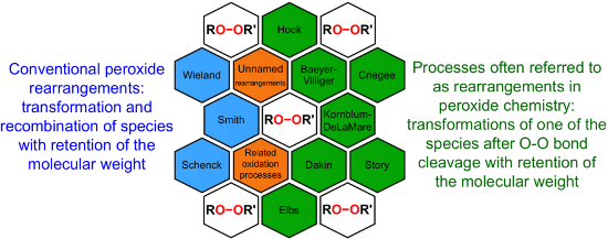

Graphical Abstract
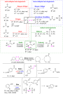
Figure 1: The named transformations considered in this review.

Scheme 1: The Baeyer–Villiger oxidation.

Scheme 2: The general mechanism of the peracid-promoted Baeyer–Villiger oxidation.

Scheme 3: General mechanism of the Lewis acid-catalyzed Baeyer–Villiger rearrangement.

Scheme 4: The theoretically studied mechanism of the BV oxidation reaction promoted by H2O2 and the Lewis aci...

Scheme 5: Proton movements in the transition states of the Baeyer–Villiger oxidation.

Scheme 6: The dependence of the course of the Baeyer–Villiger oxidation on the type of O–O-bond cleavage in t...
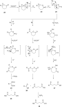
Scheme 7: The acid-catalyzed Baeyer–Villiger oxidation of cyclic epoxy ketones 22.

Scheme 8: Oxidation of isophorone oxide 29.

Scheme 9: Synthesis of acyl phosphate 32 from acyl phosphonate 31.

Scheme 10: Synthesis of aflatoxin B2 (36).

Scheme 11: The Baeyer–Villiger rearrangement of ketones 37 to lactones 38.

Scheme 12: Synthesis of 3,4-dimethoxybenzoic acid (40) via Baeyer–Villiger oxidation.

Scheme 13: Oxone transforms α,β-unsaturated ketones 43 into vinyl acetates 44.

Scheme 14: The Baeyer–Villiger oxidation of ketones 45 using diaryl diselenide and hydrogen peroxide.

Scheme 15: Baeyer–Villiger oxidation of (E)-2-methylenecyclobutanones.

Scheme 16: Oxidation of β-ionone (56) by H2O2/(BnSe)2 with formation of (E)-2-(2,6,6-trimethylcyclohex-1-en-1-...

Scheme 17: The mechanism of oxidation of ketones 58a–f by hydrogen peroxide in the presence of arsonated polys...

Scheme 18: Oxidation of ketone (58b) by H2O2 to 6-methylcaprolactone (59b) catalyzed by Pt complex 66·BF4.

Scheme 19: Oxidation of ketones 67 with H2O2 in the presence of [(dppb}Pt(µ-OH)]22+.

Scheme 20: The mechanism of oxidation of ketones 67 in the presence of [(dppb}Pt(µ-OH)]22+ and H2O2.

Scheme 21: Oxidation of benzaldehydes 69 in the presence of the H2O2/MeReO3 system.

Scheme 22: Oxidation of acetophenones 72 in the presence of the H2O2/MeReO3 system.

Scheme 23: Baeyer–Villiger oxidation of 2-adamantanone (45c) in the presence of Sn-containing mesoporous silic...

Scheme 24: Aerobic Baeyer–Villiger oxidation of ketones 76 using metal-free carbon.

Scheme 25: A regioselective Baeyer-Villiger oxidation of functionalized cyclohexenones 78 into a dihydrooxepin...

Scheme 26: The oxidation of aldehydes and ketones 80 by H2O2 catalyzed by Co4HP2Mo15V3O62.

Scheme 27: The cleavage of ketones 82 with hydrogen peroxide in alkaline solution.

Scheme 28: Oxidation of ketones 85 to esters 86 with H2O2–urea in the presence of KHCO3.

Scheme 29: Mechanism of the asymmetric oxidation of cyclopentane-1,2-dione 87a with the Ti(OiPr)4/(+)DET/t-BuO...

Scheme 30: The oxidation of cis-4-tert-butyl-2-fluorocyclohexanone (93) with m-chloroperbenzoic acid.

Scheme 31: The mechanism of the asymmetric oxidation of 3-substituted cyclobutanone 96a in the presence of chi...

Scheme 32: Enantioselective Baeyer–Villiger oxidation of cyclic ketones 98.

Scheme 33: Regio- and enantioselective Baeyer–Villiger oxidation of cyclic ketones 101.

Scheme 34: The proposed mechanism of the Baeyer–Villiger oxidation of acetal 105f.

Scheme 35: Synthesis of hydroxy-10H-acridin-9-one 117 from tetramethoxyanthracene 114.

Scheme 36: The Baeyer–Villiger oxidation of the fully substituted pyrrole 120.

Scheme 37: The Criegee rearrangement.

Scheme 38: The mechanism of the Criegee reaction of a peracid with a tertiary alcohol 122.

Scheme 39: Criegee rearrangement of decaline ethylperoxoate 127 into ketal 128.

Scheme 40: The ionic cleavage of 2-methoxy-2-propyl perester 129.

Scheme 41: The Criegee rearrangement of α-methoxy hydroperoxide 136.
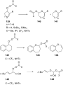
Scheme 42: Synthesis of enol esters and acetals via the Criegee rearrangement.

Scheme 43: Proposed mechanism of the transformation of 1-hydroperoxy-2-oxabicycloalkanones 147a–d.

Scheme 44: Transformation of 3-hydroxy-1,2-dioxolanes 151 into diketone derivatives 152.

Scheme 45: Criegee rearrangement of peroxide 153 with the mono-, di-, and tri-O-insertion.

Scheme 46: The sequential Criegee rearrangements of adamantanes 157a,b.

Scheme 47: Synthesis of diaryl carbonates 160a–d from triarylmethanols 159a–d through successive oxygen insert...

Scheme 48: The synthesis of sesquiterpenes 162 from ketone 161 with a Criegee rearrangement as one key step.

Scheme 49: Synthesis of trans-hydrindan derivatives 164, 165.

Scheme 50: The Hock rearrangement.

Scheme 51: The general scheme of the cumene process.

Scheme 52: The Hock rearrangement of aliphatic hydroperoxides.
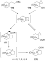
Scheme 53: The mechanism of solvolysis of brosylates 174a–c and spiro cyclopropyl carbinols 175a–c in THF/H2O2....

Scheme 54: The fragmentation mechanism of hydroperoxy acetals 178 to esters 179.

Scheme 55: The acid-catalyzed rearrangement of phenylcyclopentyl hydroperoxide 181.

Scheme 56: The peroxidation of tertiary alcohols in the presence of a catalytic amount of acid.

Scheme 57: The acid-catalyzed reaction of bicyclic secondary alcohols 192 with hydrogen peroxide.

Scheme 58: The photooxidation of 5,6-disubstituted 3,4-dihydro-2H-pyrans 196.

Scheme 59: The oxidation of tertiary alcohols 200a–g, 203a,b, and 206.

Scheme 60: Transformation of functional peroxide 209 leading to 2,3-disubstitued furans 210 in one step.

Scheme 61: The synthesis of carbazoles 213 via peroxide rearrangement.

Scheme 62: The construction of C–N bonds using the Hock rearrangement.

Scheme 63: The synthesis of moiety 218 from 217 which is a structural motif in the antitumor–antibiotic of CC-...

Scheme 64: The in vivo oxidation steps of cholesterol (219) by singlet oxygen.

Scheme 65: The proposed mechanism of the rearrangement of cholesterol-5α-OOH 220.

Scheme 66: Photochemical route to artemisinin via Hock rearrangement of 223.

Scheme 67: The Kornblum–DeLaMare rearrangement.

Scheme 68: Kornblum–DeLaMare transformation of 1-phenylethyl tert-butyl peroxide (225).

Scheme 69: The synthesis 4-hydroxyenones 230 from peroxide 229.

Scheme 70: The Kornblum–DeLaMare rearrangement of peroxide 232.

Scheme 71: The reduction of peroxide 234.

Scheme 72: The Kornblum–DeLaMare rearrangement of endoperoxide 236.

Scheme 73: The rearrangement of peroxide 238 under Kornblum–DeLaMare conditions.

Scheme 74: The proposed mechanism of rearrangement of peroxide 238.

Scheme 75: The Kornblum–DeLaMare rearrangement of peroxides 242a,b.

Scheme 76: The base-catalyzed rearrangements of bicyclic endoperoxides having electron-withdrawing substituent...

Scheme 77: The base-catalyzed rearrangements of bicyclic endoperoxides 249a,b having electron-donating substit...

Scheme 78: The base-catalyzed rearrangements of bridge-head substituted bicyclic endoperoxides 251a,b.

Scheme 79: The Kornblum–DeLaMare rearrangement of hydroperoxide 253.

Scheme 80: Synthesis of β-hydroxy hydroperoxide 254 from endoperoxide 253.

Scheme 81: The amine-catalyzed rearrangement of bicyclic endoperoxide 263.

Scheme 82: The base-catalyzed rearrangement of meso-endoperoxide 268 into 269.

Scheme 83: The photooxidation of 271 and subsequent Kornblum–DeLaMare reaction.

Scheme 84: The Kornblum–DeLaMare rearrangement as one step in the oxidation reaction of enamines.

Scheme 85: The Kornblum–DeLaMare rearrangement of 3,5-dihydro-1,2-dioxenes 284, 1,2-dioxanes 286, and tert-but...

Scheme 86: The Kornblum–DeLaMare rearrangement of epoxy dioxanes 290a–d.

Scheme 87: Rearrangement of prostaglandin H2 292.

Scheme 88: The synthesis of epicoccin G (297).

Scheme 89: The Kornblum–DeLaMare rearrangement used in the synthesis of phomactin A.

Scheme 90: The Kornblum–DeLaMare rearrangement in the synthesis of 3H-quinazolin-4-one 303.

Scheme 91: The Kornblum–DeLaMare rearrangement in the synthesis of dolabriferol (308).

Scheme 92: Sequential transformation of 3-substituted 2-pyridones 309 into 3-hydroxypyridine-2,6-diones 311 in...

Scheme 93: The Kornblum–DeLaMare rearrangement of peroxide 312 into hydroxy enone 313.

Scheme 94: The Kornblum–DeLaMare rearrangement in the synthesis of polyfunctionalized carbonyl compounds 317.

Scheme 95: The Kornblum–DeLaMare rearrangement in the synthesis of (Z)-β-perfluoroalkylenaminones 320.

Scheme 96: The Kornblum–DeLaMare rearrangement in the synthesis of γ-ketoester 322.

Scheme 97: The Kornblum–DeLaMare rearrangement in the synthesis of diterpenoids 326 and 328.

Scheme 98: The synthesis of natural products hainanolidol (331) and harringtonolide (332) from peroxide 329.

Scheme 99: The synthesis of trans-fused butyrolactones 339 and 340.

Scheme 100: The synthesis of leucosceptroid C (343) and leucosceptroid P (344) via the Kornblum–DeLaMare rearra...

Scheme 101: The Dakin oxidation of arylaldehydes or acetophenones.

Scheme 102: The mechanism of the Dakin oxidation.

Scheme 103: A solvent-free Dakin reaction of aromatic aldehydes 356.

Scheme 104: The organocatalytic Dakin oxidation of electron-rich arylaldehydes 358.

Scheme 105: The Dakin oxidation of electron-rich arylaldehydes 361.

Scheme 106: The Dakin oxidation of arylaldehydes 358 in water extract of banana (WEB).

Scheme 107: A one-pot approach towards indolo[2,1-b]quinazolines 364 from indole-3-carbaldehydes 363 through th...

Scheme 108: The synthesis of phenols 367a–c from benzaldehydes 366a-c via acid-catalyzed Dakin oxidation.

Scheme 109: Possible transformation paths of the highly polarized boric acid coordinated H2O2–aldehyde adduct 3...

Scheme 110: The Elbs oxidation of phenols 375 to hydroquinones.

Scheme 111: The mechanism of the Elbs persulfate oxidation of phenols 375 affording p-hydroquinones 376.

Scheme 112: Oxidation of 2-pyridones 380 under Elbs persulfate oxidation conditions.

Scheme 113: Synthesis of 3-hydroxy-4-pyridone (384) via an Elbs oxidation of 4-pyridone (382).

Scheme 114: The Schenck rearrangement.

Scheme 115: The Smith rearrangement.

Scheme 116: Three main pathways of the Schenck rearrangement.

Scheme 117: The isomerization of hydroperoxides 388 and 389.

Scheme 118: Trapping of dioxacyclopentyl radical 392 by oxygen.

Scheme 119: The hypothetical mechanism of the Schenck rearrangement of peroxide 394.

Scheme 120: The autoxidation of oleic acid (397) with the use of labeled isotope 18O2.

Scheme 121: The rearrangement of 18O-labeled hydroperoxide 400 under an atmosphere of 16O2.

Scheme 122: The rearrangement of the oleate-derived allylic hydroperoxides (S)-421 and (R)-425.

Scheme 123: Mechanisms of Schenck and Smith rearrangements.

Scheme 124: The rearrangement and cyclization of 433.

Scheme 125: The Wieland rearrangement.

Scheme 126: The rearrangement of bis(triphenylsilyl) 439 or bis(triphenylgermyl) 441 peroxides.

Scheme 127: The oxidative transformation of cyclic ketones.

Scheme 128: The hydroxylation of cyclohexene (447) in the presence of tungstic acid.

Scheme 129: The oxidation of cyclohexene (447) under the action of hydrogen peroxide.

Scheme 130: The reaction of butenylacetylacetone 455 with hydrogen peroxide.

Scheme 131: The oxidation of bridged 1,2,4,5-tetraoxanes.

Scheme 132: The proposed mechanism for the oxidation of bridged 1,2,4,5-tetraoxanes.

Scheme 133: The rearrangement of ozonides.

Scheme 134: The acid-catalyzed oxidative rearrangement of malondialdehydes 462 under the action of H2O2.

Scheme 135: Pathways of the Lewis acid-catalyzed cleavage of dialkyl peroxides 465 and ozonides 466.

Scheme 136: The mechanism of the transformation of (tert-butyldioxy)cyclohexanedienones 472.

Scheme 137: The synthesis of Vitamin K3 from 472a.

Scheme 138: Proposed mechanism for the transformation of 478d into silylated endoperoxide 479d.

Scheme 139: The rearrangement of hydroperoxide 485 to form diketone 486.

Scheme 140: The base-catalyzed rearrangement of cyclic peroxides 488a–g.

Scheme 141: Synthesis of chiral epoxides and aldols from peroxy hemiketals 491.

Scheme 142: The multistep transformation of (R)-carvone (494) to endoperoxides 496a–e.

Scheme 143: The decomposition of anthracene endoperoxide 499.

Scheme 144: Synthesis of esters 503 from aldehydes 501 via rearrangement of peroxides 502.

Scheme 145: Two possible paths for the base-promoted decomposition of α-azidoperoxides 502.

Scheme 146: The Story decomposition of cyclic diperoxide 506a.

Scheme 147: The Story decomposition of cyclic triperoxide 506b.

Scheme 148: The thermal rearrangement of endoperoxides A into diepoxides B.

Scheme 149: The transformation of peroxide 510 in the synthesis of stemolide (511).

Scheme 150: The possible mechanism of the rearrangement of endoperoxide 261g.

Scheme 151: The photooxidation of indene 517.

Scheme 152: The isomerization of ascaridole (523).

Scheme 153: The isomerization of peroxide 525.

Scheme 154: The thermal transformation of endoperoxide 355.

Scheme 155: The photooxidation of cyclopentadiene (529) at a temperature higher than 0 °C.

Scheme 156: The thermal rearrangement of endoperoxides 538a,b.

Scheme 157: The transformation of peroxides 541.

Scheme 158: The thermal rearrangements of strained cyclic peroxides.

Scheme 159: The thermal rearrangement of diacyl peroxide 551 in the synthesis of C4-epi-lomaiviticin B core 553....

Scheme 160: The 1O2 oxidation of tryptophan (554) and rearrangement of dioxetane intermediate 555.

Scheme 161: The Fe(II)-promoted cleavage of aryl-substituted bicyclic peroxides.

Scheme 162: The proposed mechanism of the Fe(II)-promoted rearrangement of 557a–c.

Scheme 163: The reaction of dioxolane 563 with Fe(II) sulfate.

Scheme 164: Fe(II)-promoted rearrangement of 1,2-dioxane 565.

Scheme 165: Fe(II) cysteinate-promoted rearrangement of 1,2-dioxolane 568.

Scheme 166: The transformation of 1,2-dioxanes 572a–c under the action of FeCl2.

Scheme 167: Fe(II) cysteinate-promoted transformation of tetraoxane 574.

Scheme 168: The CoTPP-catalyzed transformation of bicyclic endoperoxides 600a–d.

Scheme 169: The CoTPP-catalyzed transformation of epoxy-1,2-dioxanes.

Scheme 170: The Ru(II)-catalyzed reactions of 1,4-endoperoxide 261g.

Scheme 171: The Ru(II)-catalyzed transformation as a key step in the synthesis of elyiapyrone A (610) from 1,4-...

Scheme 172: Peroxides with antimalarial activity.

Scheme 173: The interaction of iron ions with artemisinin (616).

Scheme 174: The interaction of FeCl2 with 1,2-dioxanes 623, 624.

Scheme 175: The mechanism of reaction 623 and 624 with Fe(II)Cl2.

Scheme 176: The reaction of bicyclic natural endoperoxides G3-factors 631–633 with FeSO4.

Scheme 177: The transformation of terpene cardamom peroxide 639.
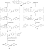
Scheme 178: The different ways of the cleavage of tetraoxane 643.

Scheme 179: The LC–MS analysis of interaction of tetraoxane 646 with iron(II)heme 647.

Scheme 180: The rearrangement of 3,6-epidioxy-1,10-bisaboladiene (EDBD, 649).

Scheme 181: Easily oxidized substrates.

Scheme 182: Biopathway of synthesis of prostaglandins.

Scheme 183: The reduction and rearrangements of isoprostanes.

Scheme 184: The partial mechanism for linoleate 658 oxidation.

Scheme 185: The transformation of lipid hydroperoxide.

Scheme 186: The acid-catalyzed cleavage of the product from free-radical oxidation of cholesterol (667).

Scheme 187: Two pathways of catechols oxidation.

Scheme 188: Criegee-like or Hock-like rearrangement of the intermediate hydroperoxide 675 in dioxygenase enzyme...

Scheme 189: Carotinoides 679 cleavage by carotenoid cleavage dioxygenases.
On the cause of low thermal stability of ethyl halodiazoacetates
- Magnus Mortén,
- Martin Hennum and
- Tore Bonge-Hansen
Beilstein J. Org. Chem. 2016, 12, 1590–1597, doi:10.3762/bjoc.12.155

- bimolecular dimerization leading to azines; and 3) a reaction of the diazo compound with the solvent or a reactant prior to nitrogen extrusion. The fact that the decomposition rate of all halodiazoacetates showed first order kinetics and that t1/2 for 2b is independent of its concentration indicates that

Graphical Abstract

Figure 1: Relative stability and nucleophilicity of non-stabilized (R = H, alkyl) diazo compounds (left) and ...

Scheme 1: Synthesis of ethyl halodiazoacetates [11].

Figure 2: a) The decay of 2b in toluene-d8 at 35 °C. b) The plot of log(Δ[2b]) vs time.

Scheme 2: Proposed rate determining step for the thermal decomposition of 2a–c.

Figure 3: Transition-state energies (kcal/mol) for the release of N2 and formation of the singlet carbenes. T...

Figure 4: Thermal stability of 1 and 2a–c, and the α-substituents’ contribution to π-donation.

Figure 5: NBO atomic charges and IR stretching frequencies calculated [21] and experimentally recorded for 1 and ...

Figure 6: NBO atomic charges of the singlet carbenes from 1 and 2a,b, and d.

Figure 7: Relative thermal stability of halodiazoacetates (red color).

Figure 8: Relative nucleophilicity of halodiazoacetates (red color).
Synthesis of ferrocenyl-substituted 1,3-dithiolanes via [3 + 2]-cycloadditions of ferrocenyl hetaryl thioketones with thiocarbonyl S-methanides
- Grzegorz Mlostoń,
- Róża Hamera-Fałdyga,
- Anthony Linden and
- Heinz Heimgartner
Beilstein J. Org. Chem. 2016, 12, 1421–1427, doi:10.3762/bjoc.12.136
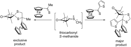
- [3 + 2]-cycloadditions. The high reactivity of ferrocenyl thioketones is demonstrated by the fact that no products of competitive reactions, such as dimerization of the intermediate 1,3-dipole or 1,3-dipolar electrocyclizations, were observed. Based on these observations one can expect that

Graphical Abstract

Scheme 1: Reactions of aromatic thiocarbonyl S-methanides 2a,b with ferrocenyl thioketones 1 (Table 1).

Figure 1: ORTEP Plot [16] of the molecular structures of the ferrocenyl-substituted 1,3-dithiolanes 5b and 5f (wi...

Scheme 2: Reactions of cycloaliphatic thiocarbonyl S-methanides with ferrocenyl hetaryl thioketones 1 (Table 1).

Scheme 3: Reaction of 3c with ferrocenyl methyl thioketone 1e.

Scheme 4: Mesomeric stabilization of the 1,5-diradical intermediate in the reaction of aromatic thiocarbonyl S...
Molecular weight control in organochromium olefin polymerization catalysis by hemilabile ligand–metal interactions
- Stefan Mark,
- Hubert Wadepohl and
- Markus Enders
Beilstein J. Org. Chem. 2016, 12, 1372–1379, doi:10.3762/bjoc.12.131
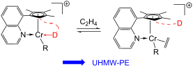
- ] and 2.3 Å–2.4 Å (Cr0) [70][71], respectively. As an alternative to the intramolecular coordination of the hemilabile donor to the vacant coordination site at the chromium center, a dimerization of the cationic methylchromium fragment could occur and examples of such dicationic dimers have been
- reported [72][73][74][75]. We were able to identify local minimum structures of dimers of compounds 3a+–8a+ but the calculated energies lie considerably higher compared to monomeric forms. Consequently, the saturation by the weak hemilabile donor is energetically preferred over dimerization. Another

Graphical Abstract

Scheme 1: Influencing catalyst stability, olefin coordination and chain-transfer reactions by hemilabile dono...

Scheme 2: Synthesis of ligands L1–L8 and chromium complexes 1–8.

Figure 1: Solid-state molecular structures of selected complexes 4, 7 and 8 (left, middle and right, respecti...

Figure 2: a) Calculated structures of cationic chromium complexes. Chromium–donor distances [Å]: 3a+ [2.21], ...

Figure 3: Comparison of GPC traces of polyethylene produced by 1/PMAO and 8/PMAO respectively (entries 1 and ...
Synthesis of 2-oxindoles via 'transition-metal-free' intramolecular dehydrogenative coupling (IDC) of sp2 C–H and sp3 C–H bonds
- Nivesh Kumar,
- Santanu Ghosh,
- Subhajit Bhunia and
- Alakesh Bisai
Beilstein J. Org. Chem. 2016, 12, 1153–1169, doi:10.3762/bjoc.12.111
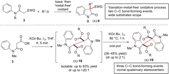
- could not isolate products due to decomposition under optimized IDC conditions. It was noticed that changing the solvent to THF effected very fast (within 5 minutes) dimerization of 3a and b at room temperature to afford 18a and b as sole products in 91–93% yield and in up to >20:1 dr (Scheme 4). This
- ], sharing a vicinal all-carbon quaternary stereogenic centers with extreme steric congestion at the C3a–C3a' σ-bond as well as the attendant lability of this linkage. Under the optimized conditions, one-pot dimerization of β-N-arylamido ester 3a and b and 9a took place in the presence of 1.2 equivalents of
- synthesis of 12b as per method A has been reproduced from reference [46]. Synthesis of spirocyclic product through IDC The synthesis of 14 as per method A has been reproduced from reference [46]. Conditions A: KOt-Bu, iodine; conditions B: KOt-Bu, NIS. Dimerization of β-N-aryl-amidoesters 3a and b

Graphical Abstract

Scheme 1: Synthesis of 2-oxindoles via oxidative processes.
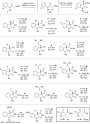
Figure 1: Substrates scope of one-pot ‘transition-metal-free’ IDC. The syntheses of compounds 4a–s according ...

Figure 2: Further substrates scope of one-pot ‘transition metal-free’ IDC. Conditions A: KOt-Bu, iodine; cond...
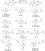
Figure 3: Substrates scope of ‘transition-metal-free’ IDC using KOt-Bu/I2. Reproduced from [46].
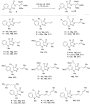
Figure 4: C-Alkylation of anilides using KOt-Bu.

Figure 5: Substrates scope of ‘transition-metal-free’ IDC of C-alkylated anilides using DBU/I2.

Scheme 2: Oxidative coupling of C-arylated anilides (±)-11a–d. The synthesis of 12b as per method A has been ...

Scheme 3: Synthesis of spirocyclic product through IDC The synthesis of 14 as per method A has been reproduce...

Scheme 4: Dimerization of β-N-aryl-amidoesters 3a and b. Reproduced from [46].

Scheme 5: Synthesis of dimeric 2-oxindoles utilizing IDC. The syntheses of 19a and b have been reproduced fro...

Scheme 6: Plausible mechanism of ‘transition-metal-free’ IDC The mechanistic consideration in Scheme 6 has been repro...

Scheme 7: Intramolecular-dehydrogenative-coupling (IDC) of 3a and 5a. Reproduced from [46].

Scheme 8: IDC of 3a and 5a using different oxidants. Reproduced from [46].

Scheme 9: Synthesis of 3-substituted-2-oxindoles from benzyl esters.

Scheme 10: 3-Substituted-2-oxindoles from p-methoxybenzyl esters.

Scheme 11: Synthetic elaboration using Tsuji–Trost reactions. Reproduced from [46].
The synthesis of functionalized bridged polycycles via C–H bond insertion
- Jiun-Le Shih,
- Po-An Chen and
- Jeremy A. May
Beilstein J. Org. Chem. 2016, 12, 985–999, doi:10.3762/bjoc.12.97
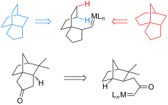
- sterically hindered catalyst such as Rh2(esp)2 or Rh2(OPiv)4 is needed to prevent dimerization of the diazoacetate. These catalysts are presumed to protect the carbene intermediates from intermolecular reactions long enough to adopt the correct conformation for bridged-ring formation. An exploration of the

Graphical Abstract

Figure 1: Bridged polycyclic natural products.

Figure 2: Strategic limitations.

Scheme 1: Bridged rings from N–H bond insertions.

Scheme 2: The synthesis of deoxystemodin.

Scheme 3: A model system for ingenol.

Scheme 4: Formal synthesis of platensimycin.

Scheme 5: The formal synthesis of gerryine.

Scheme 6: Copper-catalyzed bridged-ring synthesis.
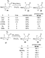
Scheme 7: Factors influencing insertion selectivity.

Scheme 8: Bridged-lactam formation.

Scheme 9: The total synthesis of (+)-codeine.

Scheme 10: A model system for irroratin.

Scheme 11: The utility of 1,6-insertion.

Scheme 12: Piperidine functionalization.

Scheme 13: Wilkinson’s catalyst for C–H bond insertion.

Scheme 14: Bridgehead insertion and the total synthesis of albene and santalene.

Scheme 15: The total synthesis of neopupukean-10-one.

Scheme 16: An approach to phomoidride B.

Scheme 17: Carbene cascade for fused bicycles.

Scheme 18: Cascade formation of bridged rings.

Scheme 19: Conformational effects.

Scheme 20: Hydrazone cascade reaction.

Scheme 21: Mechanistic studies.

Scheme 22: Gold carbene formation from alkynes.

Scheme 23: Au-catalyzed bridged-bicycle formation.

Scheme 24: Gold carbene/alkyne cascade.

Scheme 25: Gold carbene/alkyne cascade with C–H bond insertion.

Scheme 26: Platinum cascades.

Scheme 27: Tungsten cascade.
Enantioselective carbenoid insertion into C(sp3)–H bonds
- J. V. Santiago and
- A. H. L. Machado
Beilstein J. Org. Chem. 2016, 12, 882–902, doi:10.3762/bjoc.12.87
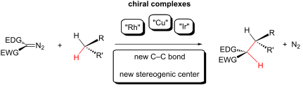
- increase of the enantioselectivity. TCE heteroaryldiazoacetates were also successfully employed for the formation of the rhodium carbenoid insertion products in superior yields when compared to the reaction with methyl aryldiazoacetates. TCE aryldiazoacetates reduced significantly the carbene dimerization

Graphical Abstract

Figure 1: Singlet carbene, triplet carbene and carbenoids.

Figure 2: Classification of the carbenoid intermediates by the electronic nature of the groups attached to th...

Figure 3: Chiral bis(oxazoline) ligands used in enantioselective copper carbenoid insertion.

Scheme 1: Pioneering work of Peter Yates on the carbenoid insertion reaction into X–H bonds (where X = O, S, ...

Scheme 2: Copper carbenoid insertion into C(sp3)–H bond of a stereogenic center with full retention of the as...

Scheme 3: Carbenoid insertion into a C(sp3)–H bond as the key step of the Taber’s (+)-α-cuparenone (8) synthe...

Scheme 4: First enantioselective carbenoid insertion into C–O bonds catalyzed by chiral metallic complexes.

Figure 4: Chemical structures of complexes (R)-18 and (S)-18.

Scheme 5: Asymmetric carbenoid insertions into C(sp3)–H bonds of cycloalkanes catalyzed by chiral rhodium car...

Scheme 6: First diastereo and enantioselective intermolecular carbenoid insertion into tetrahydrofuran C(sp3)...

Scheme 7: Simplified mechanism of the carbenoid insertion into a C(sp3)–H bond.

Scheme 8: Nakamura’s carbenoid insertion into a C(sp3)–H bond catalytic cycle.

Scheme 9: Investigation of the relationship between the electronic characteristics of the substituent X attac...

Scheme 10: Empirical model to predict the stereoselectivity of the donor/acceptor dirhodium carbenoid insertio...

Scheme 11: Asymmetric insertion of copper carbenoids in C(sp3)–H bonds to prepare trans-γ-lactam.

Figure 5: Iridium catalysts used by Suematsu and Katsuki for carbenoid insertion into C(sp3)–H bonds.

Scheme 12: Chiral porphyrin iridium complex catalyzes the carbenoid insertion into bis-allylic C(sp3)–H bonds.

Scheme 13: Chiral porphyrin iridium complex catalyzes the carbenoid insertion into tetrahydrofuran C(sp3)–H bo...

Scheme 14: Chiral porphyrin–iridium complex catalyzes the intramolecular carbenoid insertion into C(sp3)–H bon...

Scheme 15: Chiral bis(oxazoline)–iridium complex catalyzes the carbenoid insertion into bis-allylic C(sp3)–H b...

Scheme 16: New cyclopropylcarboxylate-based chiral catalyst to enantioselective carbenoid insertion into the e...

Scheme 17: Regio- and enantioselective carbenoid insertion into the C(sp3)–H bond catalyzed by a new bulky cyc...

Scheme 18: Regio and diastereoselective carbenoid insertion into the C(sp3)–H bond catalyzed by a new bulky cy...

Scheme 19: 2,2,2-Trichloroethyl (TCE) aryldiazoacetates to improve the scope, regio- and enantioselective of t...

Scheme 20: Sequential C–H functionalization approach to 2,3-dihydrobenzofurans.

Scheme 21: Enantioselective intramolecular rhodium carbenoid insertion into C(sp3)–H bonds to afford cis-disub...

Scheme 22: Enantioselective intramolecular rhodium carbenoid insertion into C(sp3)–H bonds to afford cis-2-vin...

Scheme 23: First rhodium porphyrin-based catalyst for enantioselective carbenoid insertion into C(sp3)–H bond.

Scheme 24: Rhodium porphyrin-based catalyst for enantioselective carbenoid insertion into benzylic C(sp3)–H bo...
Diradical reaction mechanisms in [3 + 2]-cycloadditions of hetaryl thioketones with alkyl- or trimethylsilyl-substituted diazomethanes
- Grzegorz Mlostoń,
- Paulina Pipiak and
- Heinz Heimgartner
Beilstein J. Org. Chem. 2016, 12, 716–724, doi:10.3762/bjoc.12.71
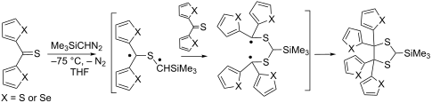
- . Remarkably, in no single case, the ‘head-to-head dimerization’ of aryl/hetaryl and dihetaryl substituted thiocarbonyl ylides was observed. Keywords: [3 + 2]-cycloadditions; diazoalkanes; diradicals; 1,3-dithiolanes; reaction mechanisms; thioketones; Introduction Cycloaddition reactions belong to the most
- ). When the decomposition of 2a or 2b was performed in the presence of a suitable dipolarophile, the corresponding [3 + 2]-cycloadducts were formed, whereas in the absence of a dipolarophile, the ‘head-to-head dimerization’ leading to 2,2,3,3-tetraaryl-1,4-dithianes 4a,b is the exclusive reaction
- total, equimolar amount of 7c. After warming up and typical work-up procedure, the corresponding 1,3-dithiolane 10o and 1,4-dithiane 4c in a ratio of 2:1 were found as products identified in the 1H NMR spectrum of the crude reaction mixture. Thus, in this reaction dimerization of the intermediate

Graphical Abstract

Scheme 1: ‘Head-to-head dimerization’ of diarylthioketone S-methanides 3a,b leading to 2,2,3,3-tetrasubstitut...

Scheme 2: Diradical nature of the reactive intermediate 3c in the reaction of phenyl selenophen-2-yl thioketo...

Scheme 3: Formation of thiiranes 8 and/or 1,3-dithiolanes 10 in the reaction of aryl/aryl, aryl/hetaryl and d...
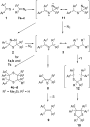
Scheme 4: Proposed competitive mechanisms in the reactions of aryl/hetaryl and dihetaryl thioketones 1 with 2...
Opportunities and challenges for direct C–H functionalization of piperazines
- Zhishi Ye,
- Kristen E. Gettys and
- Mingji Dai
Beilstein J. Org. Chem. 2016, 12, 702–715, doi:10.3762/bjoc.12.70
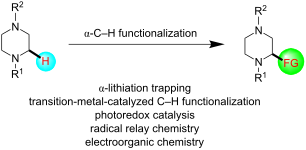
- carbon-substituted piperazines [19][20][21][22]. Mendoza et al. have developed a [3 + 3] dimerization of azomethine to synthesize highly substituted piperazines [23]. Notably, Stoltz and co-workers recently developed an enantioselective synthesis of piperazin-2-ones and piperazines using a palladium

Graphical Abstract

Figure 1: Selected piperazine-containing small-molecule pharmaceuticals.

Figure 2: Strategies for the synthesis of carbon-substituted piperazines.

Figure 3: The first α-lithiation of N-Boc-protected piperazines by van Maarseveen et al. in 2005 [37].

Figure 4: α-Lithiation of N-Boc-N’-tert-butyl piperazines by Coldham et al. in 2010 [38].

Figure 5: Diamine-free α-lithiation of N-Boc-piperazines by O’Brien, Campos, et al. in 2010 [40].

Figure 6: The first enantioselective α-lithiation of N-Boc-piperazines by McDermott et al. in 2008 [41].

Figure 7: Dynamic thermodynamic resolution of lithiated of N-Boc-piperazines by Coldham et al. in 2010 [38].

Figure 8: Enantioselective α-lithiation of N-Boc-N’-alkylpiperazines by O’Brien et al. in 2013 and 2016 [42,43].

Figure 9: Asymmetric α-functionalization of N-Boc-piperazines with Ph2CO by O’Brien et al. in 2016 [43].

Figure 10: A “chiral auxiliary” strategy toward enantiopure α-functionalized piperazines by O’Brien et al. 201...

Figure 11: Installation of methyl group at the α-position of piperazines by O’Brien et al. 2016 [43].

Figure 12: α-Lithiation trapping of C-substituted N-Boc-piperazines by O’Brien et al. 2016 [43].
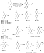
Figure 13: Rh-catalyzed reactions of N-(2-pyridinyl)piperazines by Murai et al. in 1997 [52].

Figure 14: Ta-catalyzed hydroaminoalkylation of piperazines by Schafer et al. in 2013 [55].

Figure 15: Photoredox catalysis for α-C–H functionalization of piperazines by MacMillan et al. in 2011 and 201...

Figure 16: Copper-catalyzed aerobic C–H oxidation of piperazines by Touré, Sames, et al. in 2013 [67].

Figure 17: Free radical approach by Undheim et al. in 1994 [68].

Figure 18: Anodic oxidation approach by Nyberg et al. in 1976 [70].
From steroids to aqueous supramolecular chemistry: an autobiographical career review
- Bruce C. Gibb
Beilstein J. Org. Chem. 2016, 12, 684–701, doi:10.3762/bjoc.12.69
- group at the time had worked with cavitands. In fact, John was – to cut a long story short – instrumental to Don’s publications on the synthesis and properties of soluble carceplexes formed by the dimerization and covalent linking of tetrol-cavitands (Scheme 4). When I first arrived on the scene one of
- hydrophilic portal region, then dimerization of the host will not occur. For example the binding of charged amphiphiles such as n-octanoate lead to 1:1 complexes [33][34]. With these two points noted, a wide range of guests trigger dimerization to form the capsule with ostensibly sixteen negative charges on
- sterically hinder dimerization interfere less with an assembly as the angle between the two interfacing surfaces of a pair of cavitands increases from 0° (in a dimer) to ~70.5° (in a regular tetrahedron). This senary assembly many be higher in free energy, but because this container has a volume of four

Graphical Abstract

Scheme 1: The formation of a 1:1 complex and a 2:1 supramolecular nano-capsule complex from bowl-shaped “cavi...

Scheme 2: Abbreviated synthesis of 7-amino-2-phenyl-6-azaindolizine.

Figure 1: My two favorite compounds for my Ph.D. dissertation, “The Synthesis and Structural Examination of 3...

Scheme 3: An inspiring chlorination from the group of Ronald Breslow.

Scheme 4: The carceplex reaction.
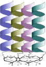
Figure 2: Schematic of a cavitein.

Figure 3: General structure of zinc-TPA complexes.

Scheme 5: Stereoselective bridging of a resorcinarene with benzal halides.

Scheme 6: An eight-fold Ullman ether “weaving” reaction.

Scheme 7: Directed ortho-metallation of the deep-cavity cavitands, showing the mono-endo substituted to tetra-...

Scheme 8: Macrocycle synthesis via resorcinarene covalent templates.

Figure 4: Tris-pyridyl hosts.

Figure 5: (Center) Chemical structure of the octa-acid host. (Left and right) Respective space-filling repres...

Figure 6: Cartoons of the 2:1 host–guest complexes of estradiol (left) and cholesterol (right).

Figure 7: Representative guests for the capsular complexes formed by octa-acid (stoichiometry shown in parent...

Figure 8: A dendrimer-coated cavitand.

Figure 9: Selective oxidation of olefins by singlet oxygen.

Figure 10: a) Preferred packing motifs of methyl, pentyl and octyl guests. b) Product distribution observed fo...

Figure 11: Schematic of the competition of two esters for the capsule formed by octa-acid. The ester that bind...

Figure 12: Schematic of the inter-phase separation of propane and butane; the latter binds more strongly to th...

Figure 13: Structure of tetra-endo-methyl octa-acid (TEMOA).

Figure 14: Assembly properties of TEMOA.

Figure 15: How salts influence the association constant (Ka) for the binding of ClO4– to octa-acid (Figure 4). The ind...
Nucleic acids through condensation of nucleosides and phosphorous acid in the presence of sulfur
- Tuomas Lönnberg
Beilstein J. Org. Chem. 2016, 12, 670–673, doi:10.3762/bjoc.12.67
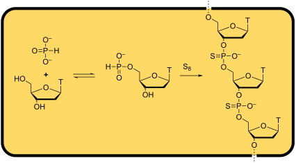
- buffer (pH 7.0). The tall peak eluting at 1.5 min in chromatogram C corresponds to either the enzyme itself or an impurity in the commercial preparation. Phosphitylation and subsequent dimerization of thymidine. Supporting Information Supporting Information File 54: Experimental methods, HPLC

Graphical Abstract

Figure 1: 31P NMR spectrum (162 MHz, D2O) of the crude product mixture after refluxing equimolar amounts of t...
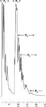
Figure 2: IE HPLC trace of the crude product mixture after refluxing equimolar amounts of thymidine and triet...
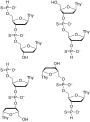
Figure 3: Possible structures of the most abundant product.

Figure 4: IE HPLC traces of (A) a mixture of tetrameric products, (B) the product mixture after desulfurizati...
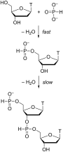
Scheme 1: Phosphitylation and subsequent dimerization of thymidine.
Biosynthesis of α-pyrones
- Till F. Schäberle
Beilstein J. Org. Chem. 2016, 12, 571–588, doi:10.3762/bjoc.12.56
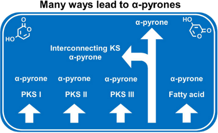
- bound substrate (Figure 25). Indeed, the exchange of this glutamate against an alanine residue resulted in an inactive version of the protein. Further an arginine residue, which could be involved in dimerization, was mutated to an aspartate. Also this mutant lost its catalytic activity, indicating that
- dimerization is essential [63]. The pseudopyronine synthase PyrS represents a homologue of PpyS. Using PpyS from Pseudomonas sp. GM30, it was analyzed if this KS is also involved in the formation of α-pyrones. The two pseudopyronines A (55) and B (56) have been up to now isolated from different Pseudomonas

Graphical Abstract

Figure 1: Selected monocyclic and monobenzo α-pyrone structures.

Figure 2: The basic core structure of dibenzo-α-pyrones.

Figure 3: Selected dibenzo-α-pyrones.

Figure 4: Structure of ellagic acid and of the urolithins, the latter metabolized from ellagic acid by intest...
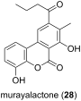
Figure 5: Structure of murayalactone, the only dibenzo-α-pyrone described from bacteria.

Figure 6: Structures of the 6-pentyl-2-pyrone (29) and of trichopyrone (30). Only 29 showed antifungal activi...

Figure 7: Selected monocyclic α-pyrones.

Figure 8: Structures of the gibepyrones A–F.

Figure 9: Structures of the phomenins A and B.

Figure 10: Structures of monocyclic α-pyrones showing pheromone (47) and antitumor activity (48), respectively....

Figure 11: Structures of 6-alkyl (alkoxy or alkylthio)-4-aryl-3-(4-methanesulfonylphenyl)pyrones.

Figure 12: Structures of kavalactones.

Figure 13: Strutures of germicins.

Figure 14: Structures of the pseudopyronines.

Figure 15: The structures of the monobenzo-α-pyrone anticoagulant drugs warfarin and phenprocoumon.

Figure 16: Structures of selected monobenzo-α-pyrones.
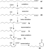
Figure 17: Hypothetical pathway of 29 generation from linoleic acid [34].

Figure 18: Proposed biosynthetic pathway of alternariol (modified from [77]). Malonyl-CoA building blocks are appl...

Figure 19: Structures of phenylnannolones and of enterocin, both biosynthesized via polyketide synthase system...

Figure 20: Pyrone ring formation. Examples for the three types of PKS systems are shown in A–C. In D the mecha...

Figure 21: Structures of csypyrones.

Figure 22: Schematic drawing of the T-shaped catalytic cavities of the related enzymes CorB and MxnB. The two ...

Figure 23: Stereo representation of the CorB binding situation (modified from [89]). The substrate mimic (dark vio...

Figure 24: Proposed mechanism for the CsyB enzymatic reaction. A) Coupling reaction of the β-keto fatty acyl i...
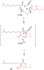
Figure 25: Proposed biosynthesis of photopyrone D (37) by the enzyme PpyS from P. luminescens (modified from [63])...
Recent advances in N-heterocyclic carbene (NHC)-catalysed benzoin reactions
- Rajeev S. Menon,
- Akkattu T. Biju and
- Vijay Nair
Beilstein J. Org. Chem. 2016, 12, 444–461, doi:10.3762/bjoc.12.47
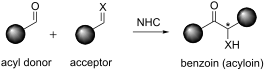
- -derived NHCs have found widespread application as catalysts for benzoin reactions, whereas triazolium-derived NHCs have emerged as popular catalysts for enantioselective benzoin transformations. Review Homo-benzoin reactions The homo-benzoin condensation constitutes an overall catalytic dimerization of an
- –Michael cascade. Divergent catalytic dimerization of 2-formylcinnamates. One-pot, multicatalytic asymmetric synthesis of tetrahydrocarbazole derivatives. NHC-chiral secondary amine co-catalysis for the synthesis of complex spirocyclic scaffolds.

Graphical Abstract
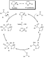
Scheme 1: Breslow’s proposal on the mechanism of the benzoin condensation.

Scheme 2: Imidazolium carbene-catalysed homo-benzoin condensation.

Scheme 3: Homo-benzoin condensation in aqueous medium.

Scheme 4: Homobenzoin condensation catalysed by bis(benzimidazolium) salt 8.

Scheme 5: List of assorted chiral NHC-catalysts used for asymmetric homobenzoin condensation.

Scheme 6: A rigid bicyclic triazole precatalyst 15 in an efficient enantioselective benzoin reaction.

Scheme 7: Inoue’s report of cross-benzoin reactions.

Scheme 8: Cross-benzoin reactions catalysed by thiazolium salt 17.

Scheme 9: Catalyst-controlled divergence in cross-benzoin reactions.

Scheme 10: Chemoselective cross-benzoin reactions catalysed by a bulky NHC.

Scheme 11: Selective intermolecular cross-benzoin condensation reactions of aromatic and aliphatic aldehydes.

Scheme 12: Chemoselective cross-benzoin reaction of aliphatic and aromatic aldehydes.

Scheme 13: Cross-benzoin reactions of trifluoromethyl ketones developed by Enders.

Scheme 14: Cross-benzoin reactions of aldehydes and α-ketoesters.

Scheme 15: Enantioselective cross-benzoin reactions of aliphatic aldehydes and α-ketoesters.

Scheme 16: Dynamic kinetic resolution of β-halo-α-ketoesters via cross-benzoin reaction.

Scheme 17: Enantioselective benzoin reaction of aldehydes and alkynones.

Scheme 18: Aza-benzoin reaction of aldehydes and acylimines.

Scheme 19: NHC-catalysed diastereoselective synthesis of cis-2-amino 3-hydroxyindanones.

Scheme 20: Cross-aza-benzoin reactions of aldehydes with aromatic imines.

Scheme 21: Enantioselective cross aza-benzoin reaction of aliphatic aldehydes with N-Boc-imines.

Scheme 22: Chemoselective cross aza-benzoin reaction of aldehydes with N-PMP-imino esters.

Scheme 23: NHC-catalysed coupling reaction of acylsilanes with imines.

Scheme 24: Thiazolium salt-mediated enantioselective cross-aza-benzoin reaction.

Scheme 25: Aza-benzoin reaction of enals with activated ketimines.

Scheme 26: Isatin derived ketimines as electrophiles in cross aza-benzoin reaction with enals.

Scheme 27: Aza-benzoin reaction of aldehydes and phosphinoylimines catalysed by the BAC-carbene.

Scheme 28: Nitrosoarenes as the electrophilic component in benzoin-initiated cascade reaction.

Scheme 29: One-pot synthesis of hydroxamic esters via aza-benzoin reaction.

Scheme 30: Cookson and Lane’s report of intramolecular benzoin condensation.

Scheme 31: Intramolecular cross-benzoin condensation between aldehyde and ketone moieties.

Scheme 32: Intramolecular crossed aldehyde-ketone benzoin reactions.

Scheme 33: Enantioselective intramolecular crossed aldehyde-ketone benzoin reaction.

Scheme 34: Chromanone synthesis via enantioselective intramolecular cross-benzoin reaction.

Scheme 35: Intramolecular cross-benzoin reaction of chalcones.

Scheme 36: Synthesis of bicyclic tertiary alcohols by intramolecular benzoin reaction.

Scheme 37: A multicatalytic Michael–benzoin cascade process for cyclopentanone synthesis.

Scheme 38: Enamine-NHC dual-catalytic, Michael–benzoin cascade reaction.

Scheme 39: Iminium-cross-benzoin cascade reaction of enals and β-oxo sulfones.

Scheme 40: Intramolecular benzoin condensation of carbohydrate-derived dialdehydes.

Scheme 41: Enantioselective intramolecular benzoin reactions of N-tethered keto-aldehydes.

Scheme 42: Asymmetric cross-benzoin reactions promoted by camphor-derived catalysts.

Scheme 43: NHC-Brønsted base co-catalysis in a benzoin–Michael–Michael cascade.

Scheme 44: Divergent catalytic dimerization of 2-formylcinnamates.

Scheme 45: One-pot, multicatalytic asymmetric synthesis of tetrahydrocarbazole derivatives.

Scheme 46: NHC-chiral secondary amine co-catalysis for the synthesis of complex spirocyclic scaffolds.
A journey in bioinspired supramolecular chemistry: from molecular tweezers to small molecules that target myotonic dystrophy
- Steven C. Zimmerman
Beilstein J. Org. Chem. 2016, 12, 125–138, doi:10.3762/bjoc.12.14
- were reported many years ago. Were the water-soluble tweezers we set out to prepare in 1985 ever made? Where does the field stand today? We found that our molecular tweezers are well preorganized for dimerization, limiting their use in water [22], whereas Klärner and colleagues discovered that their

Graphical Abstract

Figure 1: Photographs of Howard E. Zimmerman (July 5, 1926–February 12, 2012) (left) and Jane Zimmerman (née ...

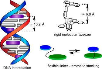
Figure 2: (a) Schematic double helix fully saturated with intercalator (in purple) according to the neighbor ...

Figure 3: Bismethidium molecular tweezer 3 proposed as a graduate student at Columbia University, which was q...

Figure 4: Adenine 8 recognition by carboxylic acid containing tweezer 9 and a component analysis showing “com...

Figure 5: The first determination of the cost of freezing single bond rotations in a host–guest complex.

Figure 6: Glycouril-based molecular clip 16 and 17 developed by Nolte, an example of Harmata’s chiral Kagan-e...

Figure 7: Macrocyclic diacridines and dinaphthalene and the intercalation complexes they may form with one ch...

Figure 8: (a) Hairpin structure of CUGexp seen in (CUG)12. (b) U–U or T–T mismatches with no inter-strand hyd...

Figure 9: (a) CTG trinucleotide repeat expansion in DMPK gene produces expanded transcripts, one which CUGexp...
Comparison of the catalytic activity for the Suzuki–Miyaura reaction of (η5-Cp)Pd(IPr)Cl with (η3-cinnamyl)Pd(IPr)(Cl) and (η3-1-t-Bu-indenyl)Pd(IPr)(Cl)
- Patrick R. Melvin,
- Nilay Hazari,
- Hannah M. C. Lant,
- Ian L. Peczak and
- Hemali P. Shah
Beilstein J. Org. Chem. 2015, 11, 2476–2486, doi:10.3762/bjoc.11.269
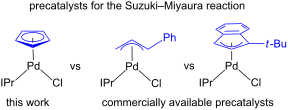
- the form of a Pd(I) dimer [13]. This suggests that Cp is more likely to undergo dimerization than Cin. CpDim was confirmed to be a poor catalyst under the conditions employed in Figure 2 (Scheme 5). This result is indicative of CpDim as an off-cycle deactivation product, which reduces the amount of

Graphical Abstract

Figure 1: General depictions of allyl and related precatalysts that are highly active for the Suzuki–Miyaura ...

Scheme 1: Synthesis of Cp.
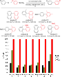
Figure 2: Comparison of catalytic performance of Cin, Cp and tBuInd for a series of Suzuki–Miyaura reactions ...
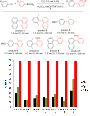
Figure 3: Comparison of catalytic performance of Cin, Cp and tBuInd for a series of Suzuki–Miyaura reactions ...

Scheme 2: Proposed mechanism for the activation of Cp to monoligated Pd(0).

Scheme 3: Synthesis of CpDim.

Figure 4: ORTEP of CpDim at 30% probability. Hydrogen atoms and isopropyl groups of IPr are omitted for clari...

Scheme 4: Observation of CpDim under modified catalytic conditions.

Scheme 5: CpDim is not an active precatalyst for a Suzuki–Miyaura reaction at room temperature.

Scheme 6: Disproportionation of CpDim with dvds.

Scheme 7: a) Crossover experiment between Cp and (μ-allyl)(μ-Cl)Pd2(IPr)2. b) Crossover experiment expressed ...
Beyond catalyst deactivation: cross-metathesis involving olefins containing N-heteroaromatics
- Kevin Lafaye,
- Cyril Bosset,
- Lionel Nicolas,
- Amandine Guérinot and
- Janine Cossy
Beilstein J. Org. Chem. 2015, 11, 2223–2241, doi:10.3762/bjoc.11.241
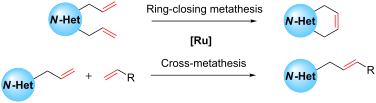
- , the addition of amino additives such as pyridine, morpholine, Et3N or DBU was shown to be detrimental to the G-HII-catalyzed dimerization of styrene (Table 2). Moderate to poor yields in stilbene 7’ were obtained and the value of the yields was correlated with the pKa of the couple ammonium/amine. An
- recommended to avoid dimerization. The most studied strategy allowing the use of olefins bearing N-heteroaromatics is the formation of the N-heteroaromatic salt prior to metathesis. The salt can be either isolated before metathesis or formed in situ using acidic additives. Alternatively, introduction of bulky

Graphical Abstract

Figure 1: Some ruthenium catalysts for metathesis reactions.

Scheme 1: Decomposition of methylidenes 1 and 2.

Scheme 2: Deactivation of G-HII in the presence of ethylene.

Scheme 3: Reaction between GI/GII and n-BuNH2.

Scheme 4: Reaction of GII with amines a–d.

Scheme 5: Amine-induced decomposition of GII methylidene 2.

Scheme 6: Amine-induced decomposition of GII in RCM conditions.

Scheme 7: Deactivation of methylidene 2 in the presence of pyridine.

Scheme 8: Reaction of G-HII with various amines.

Scheme 9: Formation of olefin 22 from styrene.

Scheme 10: Hypothetic deactivation pathway of G-HII.

Scheme 11: RCM of dienic pyridinium salts.

Scheme 12: Synthesis of polycyclic scaffolds using RCM.

Scheme 13: Enyne ring-closing metathesis.

Scheme 14: Synthesis of (R)-(+)-muscopyridine using a RCM strategy.

Scheme 15: Synthesis of a tris-pyrrole macrocycle.

Scheme 16: Synthesis of a bicyclic imidazole.

Scheme 17: RCM using Schrock’s catalyst 44.

Scheme 18: Synthesis of 1,6-pyrido-diazocine 46 by using a RCM.

Scheme 19: Synthesis of fused pyrimido-azepines through RCM.

Scheme 20: RCM involving alkenes containing various N-heteroaromatics.

Scheme 21: Synthesis of dihydroisoquinoline using a RCM.

Scheme 22: Formation of tricyclic compound 59.

Scheme 23: RCM in the synthesis of normuscopyridine.

Scheme 24: Synthesis of macrocycle 64.

Scheme 25: Synthesis of macrocycles possessing an imidazole group.

Scheme 26: Retrosynthesis of an analogue of erythromycin.

Scheme 27: Retrosynthesis of haminol A.

Scheme 28: CM involving 3-vinylpyridine 70 with 71 and vinylpyridine 70 with 73.

Scheme 29: Revised retrosynthesis of haminol A.

Scheme 30: CM between 78 and crotonaldehyde.

Scheme 31: Hypothesized deactivation pathway.

Scheme 32: CM involving an allyl sulfide containing a quinoline.

Scheme 33: CM involving allylic sulfide possessing a quinoxaline or a phenanthroline.

Scheme 34: CM between an acrylate and a 2-methoxy-5-bromo pyridine.

Scheme 35: Successful CM of an alkene containing a 2-chloropyridine.

Scheme 36: Variation of the substituent on the pyridine ring.

Scheme 37: CM involving alkenes containing a variety of N-heteroaromatics.
C–H bond halogenation catalyzed or mediated by copper: an overview
- Wenyan Hao and
- Yunyun Liu
Beilstein J. Org. Chem. 2015, 11, 2132–2144, doi:10.3762/bjoc.11.230
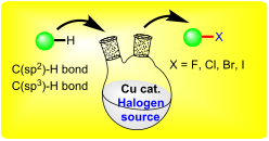
- -functionalized arene dimerization [37]. Besides the issue of selectivity, another major challenge in the DG-assisted C–H activation lied in the removal of the DG, which undermined the efficiency of the synthetic procedure. To alternate the hardly removable DG of the pyridine ring, Carretero and co-workers [38
- related C–H transformation by providing key haloarene intermediates. For examples, in the CuI-catalyzed cross arene dimerization reactions reported by Daugulis et al., the in situ formation of iodoarene intermediate was discovered as the indispensable step during the generation of the biaryl products [65

Graphical Abstract

Scheme 1: Copper-catalyzed C–H bond halogenation of 2-arylpyridine.

Scheme 2: ortho-Chlorination of 2-arylpridines with acyl chlorides.

Scheme 3: Copper-catalyzed chlorination of 2-arylpyridines using LiCl.

Scheme 4: Copper-catalyzed C–H halogenation of 2-arylpyridines using LiX.

Scheme 5: Copper-mediated selective C–H halogenations of 2-arylpyridine.

Scheme 6: Copper-catalyzed C–H o-halogenation using removable DG.

Scheme 7: Copper-catalyzed C–H halogenations using PIP as DG.

Scheme 8: Copper-catalyzed quinoline C–H chlorination.

Scheme 9: Copper-catalyzed arene C–H fluorination of benzamides.

Scheme 10: Copper-catalyzed arene C–H iodination of 1,3-azoles.

Scheme 11: Copper-catalyzed C–H halogenations of phenols.

Scheme 12: Proposed mechanism for the C–H halogenation of phenols.

Scheme 13: Copper-catalyzed halogenation of electron enriched arenes.

Scheme 14: Copper-catalyzed C–H bromination of arenes.

Scheme 15: CuI-mediated synthesis of iododibenzo[b,d]furans via C–H functionalization.

Scheme 16: Cu-Mn spinel oxide-catalyzed phenol and heteroarene halogenation.

Scheme 17: Copper-catalyzed halogenations of 2-amino-1,3thiazoles.

Scheme 18: Copper-mediated chlorination and bromination of indolizines.

Scheme 19: Copper-catalyzed three-component synthesis of bromoindolizines.

Scheme 20: Copper-mediated C–H halogenation of azacalix[1]arene[3]pyridines.

Scheme 21: Copper-mediated cascade synthesis of halogenated pyrrolones.

Scheme 22: Copper-mediated alkene C–H chlorination in spirothienooxindole.

Scheme 23: Copper-catalyzed remote C–H chlorination of alkyl hydroperoxides.
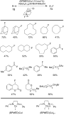
Scheme 24: Copper-catalyzed C–H fluorination of alkanes.
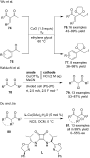
Scheme 25: Copper-catalyzed or mediated C–H halogenations of active C(sp3)-bonds.
Conformational equilibrium in supramolecular chemistry: Dibutyltriuret case
- Karina Mroczyńska,
- Małgorzata Kaczorowska,
- Erkki Kolehmainen,
- Ireneusz Grubecki,
- Marek Pietrzak and
- Borys Ośmiałowski
Beilstein J. Org. Chem. 2015, 11, 2105–2116, doi:10.3762/bjoc.11.227
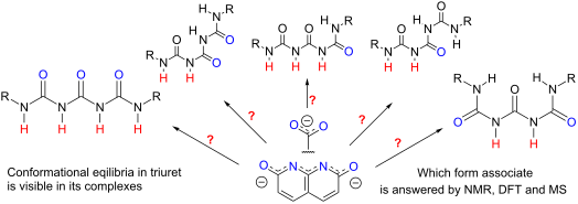
- . Mass spectrometry analysis was performed on a Q-Exactive mass spectrometer (Thermo Scientific). The Benesi–Hildebrand equation [59] was used to find association constants while the method proposed by Tan [60] was used for dimerization of 1. It was assumed that 1:1 stoichiometry is present in all

Graphical Abstract

Figure 1: The compounds used in this study and their atom numbering.

Figure 2: Possible conformations of 1.

Figure 3: Driving forces influencing association exemplified on two "extreme" conformations of 1∙∙∙benzoate.

Figure 4: Two possible, extreme multiple hydrogen bonded multimeric structures of 1 and VT 1H NMR spectra (fr...

Figure 5: The proposed structure explaining unusual behavior of the titration curve for 1∙∙∙9 titration and a...

Figure 6: Collective titration curves (H1/H7 and H3/H5 chemical shifts, CDCl3) for complex of 1 with substitu...

Figure 7: The signal labelling for [1]:[5] in 1:1 ratio exemplified on the spectra recorded at −40 °C (CDCl3)...

Figure 8: The variable temperature (+20 to −40 °C, CDCl3) dependence of the main signals (the highest integra...

Figure 9: The VT (+20 to −70 °C, CDCl3) 1H NMR stacked spectra (low temp. at bottom) for 1∙∙∙10 in 1:0.1 mola...

Figure 10: Two most probable forms of 1∙∙∙10 complex (in red) with "rotational-shift" path between them.
Supramolecular chemistry: from aromatic foldamers to solution-phase supramolecular organic frameworks
- Zhan-Ting Li
Beilstein J. Org. Chem. 2015, 11, 2057–2071, doi:10.3762/bjoc.11.222
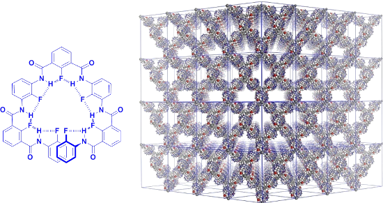
- secondary structures from aromatic backbones driven by different noncovalent forces (including hydrogen bonding, donor–acceptor, solvophobicity, and dimerization of conjugated radical cations) and solution-phase supramolecular organic frameworks driven by hydrophobically initiated aromatic stacking in the
- cavity of cucurbit[8]uril (CB[8]) are highlighted. Keywords: donor–acceptor interaction; foldamer; hydrogen bond; radical cation dimerization; supramolecular organic framework; Review Childhood and growing up I was born on July 23rd, 1966 in the small, remote village of Fang-Liu (a combination of two
- . In 1998, the group reported the extremely stable quadruple hydrogen-bonded dimers 8·8 [16] (Scheme 4). By using an 1H NMR dilution technique, a lower limit to the dimerization constant Kdim (>107 M−1) was estimated. Professor Zimmerman hoped to make an accurate determination of the binding stability

Graphical Abstract

Scheme 1: Proposed structures of complexes between 1a and 1b with 2.

Scheme 2: The formation of catenanes 6a–c.

Scheme 3: The structures of cantenanes 7a–c.

Scheme 4: The structures of dimer 8·8 and compounds 9 and 10.

Figure 1: X-ray structure of 10 showing a quadruple hydrogen-bonded dimeric motif [17].

Scheme 5: The structures of compounds 11a–g.

Figure 2: Zipper-featured folding motif of δ-peptides 11a–g driven by the cooperative donor–acceptor interact...

Scheme 6: The structures of compounds 12a–g and the formation of the helical conformation by the longer oligo...

Scheme 7: The structures of compounds 13a,b, 14, and 15a–d.

Scheme 8:
The structures of complex C60 ![[Graphic 1]](/bjoc/content/inline/1860-5397-11-222-i19.png?max-width=637&scale=1.18182) 16 and dynamic [2]catenane formed by compounds 17–19.
16 and dynamic [2]catenane formed by compounds 17–19.

Scheme 9: The structure of homodimers 20a·20a and 20b·20b.

Scheme 10: The structures of foldamers 21 and 22a–c.

Scheme 11: Complexation-promoted hydrolysis of foldamer 23.

Scheme 12: The structure of foldamer 24.

Scheme 13: The structures of foldamers 24a–c.

Scheme 14: Proposed structures of heterodimers 25·28, 26·28, and 27·28.

Scheme 15: Proposed structure of complex formed by 29 and 30.

Scheme 16: The structures of polymers P31a,b and P32a–d.

Scheme 17: The structure of compound 33.

Scheme 18: The structure of compound 34.
The marine sponge Agelas citrina as a source of the new pyrrole–imidazole alkaloids citrinamines A–D and N-methylagelongine
- Christine Cychon,
- Ellen Lichte and
- Matthias Köck
Beilstein J. Org. Chem. 2015, 11, 2029–2037, doi:10.3762/bjoc.11.220
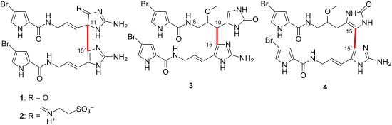
- (18). Citrinamine A (1) is the 2,2´-didebromo derivative of mauritiamine (7) and as in the original publications of 7 and 18 no chiroptical effect was observed for 1. Synthetic studies on mauritiamine (7) [14] demonstrated the formation of similar racemic products by a chemical oxidative dimerization

Graphical Abstract

Figure 1: Selected pyrrole-imidazole alkaloids (1–4, 6–11, and 13–20), and agelongine analogues (5, 12, and 21...

Figure 2: Selected 1H,1H-COSY (blue bonds), 1H,1H-NOESY (blue arrows), 1H,13C-HMBC, and 1H,15N-HMBC (both red...

Figure 3: Selected 1H,1H-COSY (blue bonds), 1H,1H-NOESY (blue arrows), 1H,13C-HMBC, and 1H,15N-HMBC (both red...

Figure 4: Selected 1H,1H-COSY (blue bonds), 1H,1H-NOESY (blue arrows), and 1H,13C-HMBC (red arrows) correlati...

Figure 5: Selected 1H,1H-COSY (blue bonds), 1H,1H-NOESY (blue arrows), 1H,13C-HMBC, and 1H,15N-HMBC (both red...

Figure 6: Selected 1H,1H-COSY (blue bonds), 1H,13C-HMBC, and 1H,15N-HMBC (both red arrows) correlations for N...
[2.2]Paracyclophane derivatives containing tetrathiafulvalene moieties
- Laura G. Sarbu,
- Lucian G. Bahrin,
- Peter G. Jones,
- Lucian M. Birsa and
- Henning Hopf
Beilstein J. Org. Chem. 2015, 11, 1917–1921, doi:10.3762/bjoc.11.207
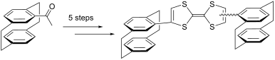
- The Cambridge Crystallographic Data Center via http://www.ccdc.cam.ac.uk/data_request/cif. The desulfurative dimerization of 1,3-dithiol-2-thione 6 was effected by heating it with trimethyl phosphite at 100 °C (Scheme 2). Purification of the crude reaction mixture by column chromatography resulted in
- isolation in order to investigate their structural and chiroptical properties. Conclusion The synthesis of as yet inseparable isomeric tetrathiafulvalenes has been performed by desulfurative dimerization of a [2.2]paracyclophane-substituted trithione. The latter compound was obtained from the corresponding

Graphical Abstract

Scheme 1: Synthesis of 2-N,N-dialkylamino-4-([2.2]paracyclophan-4-yl)-1,3-dithiol-2-ylium perchlorates 5.

Figure 1: Molecular structure of compound 4a. Ellipsoids represent 30% probability levels. Selected molecular...

Scheme 2: Synthesis of tetrathiafulvalenes 7.

Figure 2: Molecular structure of compound 6 (two independent molecules). Ellipsoids represent 30% probability...
Recent applications of ring-rearrangement metathesis in organic synthesis
- Sambasivarao Kotha,
- Milind Meshram,
- Priti Khedkar,
- Shaibal Banerjee and
- Deepak Deodhar
Beilstein J. Org. Chem. 2015, 11, 1833–1864, doi:10.3762/bjoc.11.199
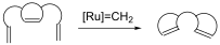
- dimerized 16-membered ring product 101 in 57% yield, which was generated by a RRM–dimerization sequence and its monomer 100 in 14% yield along with 99 in 26% yield (Scheme 20). Bicyclo[2.2.1]heptene derivatives Holtsclaw and Koreeda [25] have explored a chemoselective RRM of the enone containing norbornene

Graphical Abstract

Figure 1: Ruthenium alkylidene catalysts used in RRM processes.
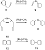
Figure 2: General representation of various RRM processes.

Figure 3: A general mechanism for RRM process.

Scheme 1: RRM of cyclopropene systems.

Scheme 2: RRM of cyclopropene with catalyst 2. (i) catalyst 2 (2.5 mol %), ethylene (24, 1 atm), (ii) toluene...

Scheme 3: RRM of various cyclopropene derivatives with catalyst 2. (i) catalyst 2 (2.5 mol %), CH2Cl2 (c = 0....

Scheme 4: RRM of substituted cyclopropene system with catalyst 2.

Scheme 5: RRM of cyclobutene system with catalyst 2.

Scheme 6: RRM approach to various bicyclic compounds.

Scheme 7: RRM approach to erythrina alkaloid framework.

Scheme 8: ROM–RCM sequence to lactone derivatives.

Scheme 9: RRM protocol towards the synthesis of lactone derivative 58.

Scheme 10: RRM protocol towards the asymmetric synthesis of asteriscunolide D (61).

Scheme 11: RRM strategy towards the synthesis of various macrolide rings.

Scheme 12: RRM protocol to dipiperidine system.

Scheme 13: RRM of cyclopentene system to generate the cyclohexene systems.

Scheme 14: RRM of cyclopentene system 74.

Scheme 15: RRM approach to compound 79.

Scheme 16: RRM approach to spirocycles.

Scheme 17: RRM approach to bicyclic dihydropyrans.

Scheme 18: RCM–ROM–RCM cascade using non strained alkenyl heterocycles.

Scheme 19: First ROM–RCM–ROM–RCM cascade for the synthesis of trisaccharide 97.

Scheme 20: RRM of cyclohexene system.

Scheme 21: RRM approach to tricyclic spirosystem.

Scheme 22: RRM approach to bicyclic building block 108a.

Scheme 23: ROM–RCM protocol for the synthesis of the bicyclo[3.3.0]octene system.

Scheme 24: RRM protocol to bicyclic enone.

Scheme 25: RRM protocol toward the synthesis of the tricyclic system 118.

Scheme 26: RRM approach toward the synthesis of the tricyclic enones 122a and 122b.

Scheme 27: Synthesis of tricyclic and tetracyclic systems via RRM protocol.

Scheme 28: RRM protocol towards the synthesis of tetracyclic systems.

Scheme 29: RRM of the propargylamino[2.2.1] system.

Scheme 30: RRM of highly decorated bicyclo[2.2.1] systems.

Scheme 31: RRM protocol towards fused tricyclic compounds.

Scheme 32: RRM protocol to functionalized tricyclic systems.

Scheme 33: RRM approach to functionalized polycyclic systems.

Scheme 34: Sequential RRM approach to functionalized tricyclic ring system 166.

Scheme 35: RRM protocol to functionalized CDE tricyclic ring system of schintrilactones A and B.

Scheme 36: Sequential RRM approach to 7/5 fused bicyclic systems.

Scheme 37: Sequential ROM-RCM protocol for the synthesis of bicyclic sugar derivatives.

Scheme 38: ROM–RCM sequence of the norbornene derivatives 186 and 187.

Scheme 39: RRM approach toward highly functionalized bridge tricyclic system.

Scheme 40: RRM approach toward highly functionalized tricyclic systems.

Scheme 41: Synthesis of hexacyclic compound 203 by RRM approach.

Scheme 42: RRM approach toward C3-symmetric chiral trimethylsumanene 209.

Scheme 43: Triquinane synthesis via IMDA reaction and RRM protocol.

Scheme 44: RRM approach to polycyclic compounds.

Scheme 45: RRM strategy toward cis-fused bicyclo[3.3.0]carbocycles.

Scheme 46: RRM protocol towards the synthesis of bicyclic lactone 230.

Scheme 47: RRM approach to spiro heterocyclic compounds.

Scheme 48: RRM approach to spiro heterocyclic compounds.

Scheme 49: RRM approach to regioselective pyrrolizidine system 240.

Scheme 50: RRM approach to functionalized bicyclic derivatives.

Scheme 51: RRM approach to tricyclic derivatives 249 and 250.

Scheme 52: RRM approach to perhydroindoline derivative and spiro system.

Scheme 53: RRM approach to bicyclic pyran derivatives.

Scheme 54: RRM of various functionalized oxanorbornene systems.

Scheme 55: RRM to assemble the spiro fused-furanone core unit. (i) 129, benzene, 55 °C, 3 days; (ii) Ph3P=CH2B...

Scheme 56: RRM protocol to norbornenyl sultam systems.

Scheme 57: Ugi-RRM protocol for the synthesis of 2-aza-7-oxabicyclo system.

Scheme 58: Synthesis of spiroketal systems via RRM protocol.

Scheme 59: RRM approach to cis-fused heterotricyclic system.

Scheme 60: RRM protocol to functionalized bicyclic systems.

Scheme 61: ROM/RCM/CM cascade to generate bicyclic scaffolds.

Scheme 62: RCM of ROM/CM product.

Scheme 63: RRM protocol to bicyclic isoxazolidine ring system.

Scheme 64: RRM approach toward the total synthesis of (±)-8-epihalosaline (300).

Scheme 65: Sequential RRM approach to decalin 304 and 7/6 fused 305 systems.

Scheme 66: RRM protocol to various fused carbocyclic derivatives.

Scheme 67: RRM to cis-hydrindenol derivatives.

Scheme 68: RRM protocol towards the cis-hydrindenol derivatives.

Scheme 69: RRM approach toward the synthesis of diversed polycyclic lactams.

Scheme 70: RRM approach towards synthesis of hexacyclic compound 324.

Scheme 71: RRM protocol to generate luciduline precursor 327 with catalyst 2.

Scheme 72: RRM protocol to key building block 330.

Scheme 73: RRM approach towards the synthesis of key intermediate 335.

Scheme 74: RRM protocol to highly functionalized spiro-pyran system 339.

Scheme 75: RRM to various bicyclic polyether derivatives.
Nitro-Grela-type complexes containing iodides – robust and selective catalysts for olefin metathesis under challenging conditions
- Andrzej Tracz,
- Mateusz Matczak,
- Katarzyna Urbaniak and
- Krzysztof Skowerski
Beilstein J. Org. Chem. 2015, 11, 1823–1832, doi:10.3762/bjoc.11.198
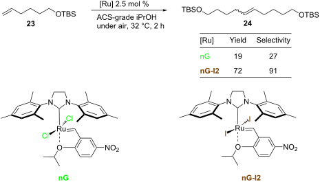
- worse than nG-SIPr. As outlined in Table 2, all tested catalysts were similarly effective in CM of methyl undecenoate 12 with cis-1,4-diacetoxy-2-butene (13), but parent dichloro complexes provided smaller quantities of dimerization product of 12. In CM of 12 with electron deficient methyl acrylate 15

Graphical Abstract

Figure 1: The diversity of Hoveyda-type complexes (Mes – 2,4,6-trimethylphenyl, DIPP – 2,6-diisopropylphenyl)....

Scheme 1: Modifications of the 2nd generation alkylidene complexes.

Scheme 2: Synthesis of iodide-containing nitro-Grela type catalysts.

Figure 2: Reaction profiles for RCM of DEDAM; toluene, 0.2 M, 18 °C, [Ru] 0.15 mol %; conversion determined b...

Figure 3: RCM of 1 (toluene, 0.05 M, 25 °C, [Ru] 0.01 mol %); blue diamonds – original (pre)catalysts; red sq...

Figure 4: RCM of 1 (toluene, 0.05 M, 25 °C, [Ru] 0.01 mol %): top – productive RCM and possible non-productiv...
SmI2-mediated dimerization of indolylbutenones and synthesis of the myxobacterial natural product indiacen B
- Nils Marsch,
- Peter G. Jones and
- Thomas Lindel
Beilstein J. Org. Chem. 2015, 11, 1700–1706, doi:10.3762/bjoc.11.184
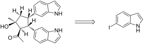
- -configuration were formed by SmI2-mediated reductive dimerization of a 4-(indol-6-yl)butenone, obtained by Heck reaction. The two indolyl units appear to chelate Sm(II)/(III) leading to a gauche-type arrangement at the newly formed bond between the two β-carbons. Through a sequence of Sonogashira cross coupling
- plants [1][2][3] and also in fungi [4] and myxobacteria [5][6]. One example is raputindole A (1), isolated in 2010 from the Rutaceous tree Raputia simulans Kallunki [1], which exhibits a unique tetrahydrocyclopenta[f]indole partial structure (Figure 1) probably formed by dimerization of (E)-6-(3
- their reductive dimerization. We also describe the synthesis of the antimicrobial natural product indiacen B (2) from the myxobacterium Sandaracinus amylolyticus [5], bearing a unique isoprene moiety chlorinated at the methylene group. Results and Discussion SmI2-induced reductive dimerizations 6

Graphical Abstract

Figure 1: Prenylated indole alkaloids raputindole A from the rutaceous tree Raputia simulans and indiacen B f...
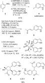
Scheme 1: Synthesis and SmI2-mediated reductive dimerization of natural product 5.

Scheme 2: Model visualizing the stereochemical course of the cyclopentanol formation leading to product 6. Po...
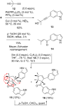
Scheme 3: Meyer–Schuster rearrangement of 13 and SmI2-mediated reductive [3 + 2] cycloaddition, followed by e...

Scheme 4: Nazarov-type cyclization of 14 to cyclopentanones 17 and 18; synthesis of verticillatine B (20).

Scheme 5: Synthesis and X-ray analysis of indiacen B (2, ORTEP drawing with ellipsoides at 50% probability).
Star-shaped tetrathiafulvalene oligomers towards the construction of conducting supramolecular assembly
- Masahiko Iyoda and
- Masashi Hasegawa
Beilstein J. Org. Chem. 2015, 11, 1596–1613, doi:10.3762/bjoc.11.175
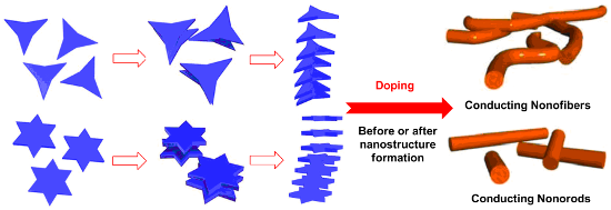
- showed two reversible two-electron redox waves at −0.03 and 0.38 V vs Fc/Fc+ in benzonitrile under normal conditions [25][60]. Conducting nanostructure formation from star-shaped oligo-TTFs Although pristine TTF does not self-associate in solution due to the low association constant for dimerization, the
- tris(TTF)[18]annulene 32. Star-shaped TTF oligomers 38–43. Pyridazine-3,6-diol-TTF 45 and its trimer 46. Redox potentials of 16–19 and absorption maxima of monocations 16•+, 17•+, 18•+ and 19•+, and dications 162+, 172+, 182+ and 192+ [25][59]. Association (dimerization) constants and thermodynamic

Graphical Abstract

Figure 1: Radially expanded TTF oligomers 1 and 2a,b.

Figure 2: TTF-calix[4]pyrrole 3 and its TNT and C60 complexes 4 and 5.

Figure 3: C3-symmetric TTF derivatives 6a,b and 7a–c.

Figure 4: Radially expanded TTF derivatives 8, 9, and 10a,b.

Figure 5: Amphiphilic TTFs 11–14 and 15a,b.

Figure 6: TTF dimers linked by σ-bond (16) and conjugated π-systems (17–19).

Scheme 1: Synthesis of star-shaped TTF trimers 22 and 23.

Figure 7: Projections of the molecular array of 22 in crystal structure (a) along with the c axis and (b) fro...

Figure 8: UV–vis/NIR spectra of 23, 23•+, 233+, and 236+.

Scheme 2: Synthesis of tris(TTF)[12]annulenes 28 and 29 and tris(TTF)[18]annulenes 30 and 31, together with h...

Figure 9: TTF-fused annulene 33 and radiannulenes 34 and 35.

Figure 10: Colors of 30 solutions a–d in toluene (0.025 mM) at various temperatures. (a) λmax: 511 nm, (b) λmax...

Figure 11: Solutions of 33. (a) In CS2, λmax: 608 nm. (b) In CH2Cl2, λmax: 577 nm. Reprinted with permission f...

Figure 12: Optical micrographs (1000× magnified) of fibers, prepared from 30 in THF–H2O 1:1, on a glass plate ...
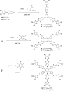
Scheme 3: Star-shaped TTF oligomers 38–43.

Figure 13: Star-shaped TTF 10-mer 44.

Figure 14: Cyclic voltammograms of 38, 40, and 42 (0.1 mM) in benzonitrile with 0.1 M n-Bu4PF6 as a supporting...

Figure 15: Stepwise oxidation of (a) 38 (0.02 mM), (b) 40 (0.05 mM), and (c) 42 (0.03 mM) with incremental add...

Scheme 4: Pyridazine-3,6-diol-TTF 45 and its trimer 46.

Figure 16: CT-complex of 47 with TCNQF4.

Figure 17: (a) Star-shaped TTF hexamer 48. (b) Optical image of 48 fiber with a hexagonal structure. (c) Optic...