Search results
Search for "antineoplastic" in Full Text gives 25 result(s) in Beilstein Journal of Organic Chemistry.
Synthesis and characterization of a isothiouronium-calix[4]arene derivative: self-assembly and anticancer activity
- Giuseppe Granata,
- Loredana Ferreri,
- Claudia Giovanna Leotta,
- Giovanni Mario Pitari and
- Grazia Maria Letizia Consoli
Beilstein J. Org. Chem. 2025, 21, 2535–2541, doi:10.3762/bjoc.21.195

- compound 3 than healthy, non-malignant cells. In general, SI values above 12 are associated to remarkable selectivity, 6–12 to moderate selectivity and 1–5 to weak selectivity [43][47]. In contrast, the potent antineoplastic agent doxorubicin, used as the positive control for anticancer effects, did not

Graphical Abstract

Scheme 1: Procedure for the synthesis of compound 3.

Figure 1: 1H NMR (left) and 13C NMR (right) spectra of compound 3 in DMSO-d6 (400.13 MHz, 297 K).

Figure 2: Intensity-weighted mean hydrodynamic diameter (left), and zeta potential distribution (right) of co...

Figure 3: Antiproliferative effects by compound 3 and its chemical precursor 1. A) Results on proliferative k...
Harnessing unprotected deactivated amines and arylglyoxals in the Ugi reaction for the synthesis of fused complex nitrogen heterocycles
- Javier Gómez-Ayuso,
- Pablo Pertejo,
- Tomás Hermosilla,
- Israel Carreira-Barral,
- Roberto Quesada and
- María García-Valverde
Beilstein J. Org. Chem. 2024, 20, 1758–1766, doi:10.3762/bjoc.20.154

- search of new bioactive compounds, as evidenced by the fact that they are present in many marketed drugs [1][2]. These substructures are found fused with other heterocycles in many cases, as illustrated by the antineoplastic dibromophakellstatin [3][4][5][6], the CDK inhibitor trilaciclib [7] or the

Graphical Abstract

Figure 1: Fused heterocycles containing the piperazine and diazepine core.

Scheme 1: Synthesis of benzodiazepinones 5 from anthranilic acid derivatives.

Scheme 2: Diastereoselective one-pot synthesis of benzodiazepinones 6.

Scheme 3: Synthesis of bis-1,4-benzodiazepines 7.

Scheme 4: Synthesis of benzodiazepinone 5c and pyrrolobenzodiazepinone 8 from anthranilic acid and 3-bromopro...

Scheme 5: Synthesis of pyrrolopiperazinones 9 from pyrrole and indole carboxylic acids.

Scheme 6: Synthesis of pyrrolopiperazinones 10 from N-phenylglicine.

Figure 2: X-ray diffraction structures of pyrrolopiperazinones 9a (left) and 10a (right). The thermal ellipso...

Scheme 7: Synthesis of pyrrolopiperazinone 11 using (S)-α-methylbenzylamine.

Scheme 8: Proposed mechanism in the spontaneous cyclization of Ugi adducts obtained from arylglyoxals and dea...

Scheme 9: Synthesis of pyrrolopiperazinoquinazolines 13.

Scheme 10: Synthesis of piperazinoquinazoline 14.

Scheme 11: Synthesis of dipyrrolopiperazinones 12.

Figure 3: X-ray diffraction structure of dipyrrolopiperazinone 12c. The thermal ellipsoid plot (Olex2) is at ...
Synthesis of ether lipids: natural compounds and analogues
- Marco Antônio G. B. Gomes,
- Alicia Bauduin,
- Chloé Le Roux,
- Romain Fouinneteau,
- Wilfried Berthe,
- Mathieu Berchel,
- Hélène Couthon and
- Paul-Alain Jaffrès
Beilstein J. Org. Chem. 2023, 19, 1299–1369, doi:10.3762/bjoc.19.96


Graphical Abstract

Figure 1: Chemical structure of some natural ether lipids (ELs).

Figure 2: Synthesis of lyso-PAF and PAF from 1-O-alkylglycerol [64].

Figure 3: Synthesis of lyso-PAF from 1,3-benzylideneglycerol 3.1 [69].

Figure 4: A) Synthesis of the two enantiomers of octadecylglycerol (4.6 and 4.10) from ᴅ-mannitol (4.1); B) s...

Figure 5: Four-step synthesis of PAF 5.6 from (S)-glycidol [73].

Figure 6: Synthesis of 1-O-alkylglycerol A) from solketal, B) from ᴅ- or ʟ-tartaric acid and the intermediate ...

Figure 7: Synthesis of EL building blocks starting from substituted glycidol 7.1a–c [82].

Figure 8: Synthesis of PAF 8.5 by using phosphoramidite 8.2 [86].

Figure 9: Synthesis of oleyl-PAF 9.7 from ʟ-serine [88].

Figure 10: Synthesis of racemic analogues of lyso-PAF 10.8 and PAF 10.9 featuring a phenyl group between the g...

Figure 11: Synthesis of racemic deoxy-lyso-PAF 11.7 and deoxy-PAF 11.8 [91].

Figure 12: Synthesis of racemic thio-PAF 12.8 [93].

Figure 13: Racemic synthesis of 13.6 to illustrate the modification of the glycerol backbone by adding a methy...

Figure 14: Racemic synthesis of 14.5 as an illustration of the introduction of methyl substituents on the glyc...

Figure 15: Synthesis of functionalized sn-2-acyl chains of PC-EL; A) Steglich esterification or acylation reac...

Figure 16: Synthesis of racemic mc-PAF (16.3), a carbamate analogue of PAF [102].

Figure 17: A) Synthesis of (R)-17.2 and (S)-17.6 starting from (S)-solketal (17.1); B) synthesis of N3-PAF (17...

Figure 18: Modification of the phosphocholine polar head to produce PAF analogues [81].

Figure 19: Racemic PAF analogues 19.3 and 19.5 characterized by the absence of the phosphate group [107].

Figure 20: Synthesis of PIP3-PAF (20.7) [108].

Figure 21: Large-scale synthesis of C18-edelfosine (21.8) [116].

Figure 22: Synthesis of C16-edelfosine (22.10) starting from isopropylidene-ʟ-glyceric acid methyl ester (22.1...

Figure 23: Phosphocholine moiety installation by the use of chlorophosphite 23.2 as key reagent [119].

Figure 24: Synthesis of rac-1-alkyl-2-O-methylglycerol (AMG) [120].

Figure 25: Synthesis of stereocontrolled 1-alkyl-2-O-methyl glycerol 25.9 (AMG) from dimethyl ᴅ-tartrate [81].

Figure 26: A) Racemic synthesis of thioether 26.4 [129,130], B) structure of sulfone analogue 26.5 [129].

Figure 27: Stereocontrolled synthesis of C18-edelfosine thioether analogue 27.8 [118].

Figure 28: Synthesis of thioether 28.4 that include a thiophosphate function [134].

Figure 29: Synthesis of ammonium thioether 29.4 and 29.6 [135].

Figure 30: Synthesis of the N-methylamino analogue of edelfosine 30.6 (BN52211) [138].

Figure 31: Synthesis of 1-desoxy analogues of edelfosine; A) with a saturated alkyl chain; B) synthesis of the...

Figure 32: Stereocontrolled synthesis of edelfosine analogue (S)-32.8 featuring a C18:1 lipid chain [142].

Figure 33: Synthesis of edelfosine analogues with modulation of the lipid chain; A) illustration with the synt...

Figure 34: Synthesis of phospholipid featuring a carbamate function to link the lipid chain to the glycerol un...

Figure 35: Synthesis of sesquiterpene conjugates of phospho glycero ether lipids [148].

Figure 36: Racemic synthesis of methyl-substituted glycerol analogues 36.7 and 36.10: A) synthesis of diether ...

Figure 37: Racemic synthesis of ilmofosine (37.6) [155,156].

Figure 38: A) Stereoselective synthesis of 38.5 via a stereoselective hydroboration reaction; B) synthesis of ...

Figure 39: Racemic synthesis of SRI62-834 (39.6) featuring a spiro-tetrahydrofurane heterocycle in position 2 ...

Figure 40: Racemic synthesis of edelfosine analogue 40.5 featuring an imidazole moiety in sn-2 position [160].

Figure 41: Racemic synthesis of fluorine-functionalized EL: A) Synthesis of 41.6 and B) synthesis of 41.8 [161-163].

Figure 42: A) Synthesis of the β-keto-ester 42.6 that also features a decyl linker between the phosphate and t...

Figure 43: Synthesis of phosphonate-based ether lipids; A) edelfosine phosphonate analogue 43.7 and B) thioeth...

Figure 44: Enantioselective synthesis of phosphonates 44.3 and 44.4 [171].

Figure 45: Racemic synthesis of phosphinate-based ether lipid 45.10 [172].

Figure 46: Racemic synthesis of edelfosine arsonium analogue 46.5 [173].

Figure 47: Synthesis of edelfosine dimethylammonium analogue 47.2 [118].

Figure 48: Synthesis of rac-C18-edelfosine methylammonium analogue 48.4 [176].

Figure 49: A) Synthesis of edelfosine N-methylpyrrolidinium analogue 49.2 or N-methylmorpholinium analogue 49.3...

Figure 50: A) Synthesis of edelfosine’s analogue 50.4 with a PE polar group; B) illustration of a pyridinium d...

Figure 51: A) Synthesis of 51.4 featuring a thiazolium cationic moiety; B) synthesis of thiazolium-based EL 51...

Figure 52: Synthesis of cationic ether lipids 52.3, 52.4 and 52.6 [135,183].

Figure 53: Synthesis of cationic carbamate ether lipid 53.5 [184].

Figure 54: Synthesis of cationic sulfonamide 54.5 [185].

Figure 55: Chemical structure of ONO-6240 (55.1) and SRI-63-119 (55.2).

Figure 56: Synthesis of non-ionic ether lipids 56.2–56.9 [188].

Figure 57: Synthesis of ether lipid conjugated to foscarnet 57.6 [189].

Figure 58: A) Synthesis of ether lipid conjugated to arabinofuranosylcytosine; B) synthesis of AZT conjugated ...

Figure 59: Synthesis of quercetin conjugate to edelfosine [191].

Figure 60: Synthesis of 60.8 (Glc-PAF) [194].

Figure 61: A) Synthesis of amino ether lipid 61.7 functionalized with a rhamnose unit and its amide analogue 6...

Figure 62: A) Synthesis of glucose ether lipid 62.4; B) structure of ether lipid 62.5 possessing a maltose uni...

Figure 63: A) Synthesis of glucuronic methyl ester 63.8; B) structure of cellobiose 63.9 and maltose 63.10 ana...

Figure 64: A) Synthesis of maltosyl glycerolipid 64.7; B) structure of lactose analogue 64.8 prepared followin...

Figure 65: A) Asymmetric synthesis of the aglycone moiety starting from allyl 4-methoxyphenyl ether; B) glycos...

Figure 66: A) Synthesis of ohmline possessing a lactose moiety. B) Structure of other glyco glycero lipids pre...

Figure 67: A) Synthesis of lactose-glycerol ether lipid 67.5; B) analogues possessing a maltose (67.6) or meli...

Figure 68: Synthesis of digalactosyl EL 68.6, A) by using trityl, benzyl and acetyl protecting groups, B) by u...

Figure 69: A) Synthesis of α-ohmline; B) structure of disaccharide ether lipids prepared by using similar meth...

Figure 70: Synthesis of lactose ether lipid 70.3 and its analogue 70.6 featuring a carbamate function as linke...

Figure 71: Synthesis of rhamnopyranoside diether 71.4 [196].

Figure 72: Synthesis of 1-O-hexadecyl-2-O-methyl-3-S-(α-ᴅ-1'-thioglucopyranosyl)-sn-glycerol (72.5) [225].

Figure 73: A) Preparation of lipid intermediate 73.4; B) synthesis of 2-desoxy-C-glycoside 73.10 [226].

Figure 74: Synthesis of galactose-pyridinium salt 74.3 [228].

Figure 75: Synthesis of myo-inositol derivative Ino-C2-PAF (75.10) [230].

Figure 76: A) Synthesis of myo-inositol phosphate building block 76.7; B) synthesis of myo-inositolphosphate d...

Figure 77: A) Synthesis of phosphatidyl-3-desoxy-inositol 77.4; B) synthesis of phosphono-3-desoxyinositol 77.9...

Figure 78: A) Structure of diether phosphatidyl-myo-inositol-3,4-diphosphate 78.1; B) synthesis of phosphatidy...

Figure 79: A) Synthesis of diether-phosphatidyl derivative 79.4 featuring a hydroxymethyl group in place of a ...

Figure 80: Synthesis of Glc-amine-PAF [78].

Figure 81: Synthesis of glucosamine ether lipid 81.4 and its analogues functionalized in position 3 of the ami...

Figure 82: Synthesis of fully deprotected aminoglucoside ether lipid 82.5 [246].

Figure 83: Synthesis of C-aminoglycoside 83.12 using Ramberg–Bäcklund rearrangement as a key step [250].

Figure 84: A) List of the most important glyco lipids and amino glyco lipids included in the study of Arthur a...

Figure 85: Synthesis of mannosamine ether lipid 85.6 [254].

Figure 86: A) Synthesis of glucosamine ether lipids with a non-natural ʟ-glucosamine moiety; B) synthesis of e...

Figure 87: A) Structure of the most efficient anticancer agents 87.1–87.4 featuring a diamino glyco ether lipi...

Figure 88: A) Synthesis of diamino glyco ether lipid 87.4; B) synthesis of bis-glycosylated ether lipid 88.10 [256]....

Figure 89: Synthesis of triamino ether lipid 89.4 [260].

Figure 90: Synthesis of chlorambucil conjugate 90.7 [261].

Figure 91: Three main methods for the preparation of glycerol ether lipid 91.3; A) from solketal and via a tri...

Figure 92: Four different methods for the installation of the phosphocholine polar head group; A) method using...

Figure 93: Illustration of two methods for the installation of saccharides or aminosaccharides; A) O-glycosyla...
Combretastatins D series and analogues: from isolation, synthetic challenges and biological activities
- Jorge de Lima Neto and
- Paulo Henrique Menezes
Beilstein J. Org. Chem. 2023, 19, 399–427, doi:10.3762/bjoc.19.31

- characterized as an oxa[1.7]meta-paracyclophane framework. In the literature we can find reports about the isolation/synthesis of combretastatins D and their analogues which showed different biological activities, e.g., antineoplastic, anti-inflammatory, and α-glucosidase inhibition [13][14][15]. The presence

Graphical Abstract

Figure 1: Structures of some members of the combretastatin D series, corniculatolides, and isocorniculatolide...

Scheme 1: Biosynthetic pathway proposed by Pettit and co-workers.

Scheme 2: Biosynthetic pathway towards corniculatolides or isocorniculatolides proposed by Ponnapalli and co-...

Scheme 3: Retrosynthetic approaches.

Scheme 4: Attempt of total synthesis of 2 by Boger and co-workers employing the Mitsunobu approach [27].

Scheme 5: Total synthesis of combretastatin D-2 (2) reported by Boger and co-workers employing an intramolecu...

Scheme 6: Formal synthesis of combretastatin D-2 (2) by Deshpande and co-workers using the Mitsunobu conditio...

Scheme 7: Total synthesis of combretastatin D-2 (2) by Rychnovsky and Hwang [36].

Scheme 8: Divergent synthesis of (±)-1 form combretastatin D-2 (2) by Rychnovsky and Hwang [36].

Scheme 9: Enantioselective synthesis of 1 by Rychnovsky and Hwang employing Jacobsen catalyst [41].

Scheme 10: Synthesis of fragment 57 by Couladouros and co-workers [43,45].

Scheme 11: Formal synthesis of compound 2 by Couladouros and co-workers [43,45].

Scheme 12: Synthesis of fragment 66 by Couladouros and co-workers [44,45].

Scheme 13: Synthesis of fragment 70 by Couladouros and co-workers [44,45].

Scheme 14: Synthesis of fragment 77 by Couladouros and co-workers [44,45].

Scheme 15: Synthesis of combretastatins 1 and 2 by Couladouros and co-workers [44,45].

Scheme 16: Formal synthesis of compound 2 by Gangakhedkar and co-workers [48].

Scheme 17: Synthesis of fragment 14 by Cousin and co-workers [50].

Scheme 18: Synthesis of fragment 91 by Cousin and co-workers [50].

Scheme 19: Formal synthesis of compound 2 by Cousin and co-workers [50].

Scheme 20: Synthesis of 2 diolide by Cousin and co-workers [50].

Scheme 21: Synthesis of combretastatin D-4 (4) by Nishiyama and co-workers [54].

Scheme 22: Synthesis of fragment 112 by Pettit and co-workers [55].

Scheme 23: Synthesis of fragment 114 by Pettit and co-workers [55].

Scheme 24: Attempt to the synthesis of compound 2 by Pettit and co-workers [55].

Scheme 25: Synthesis of combretastatin-D2 (2) starting from isovanilin (80) by Pettit and co-workers [55].

Scheme 26: Attempted synthesis of combretastatin-D2 (2) derivatives through an SNAr approach [55].

Scheme 27: Synthesis of combretastatin D-4 (4) by Pettit and co-workers [55].

Scheme 28: Synthesis of combretastatin D-2 (2) by Harras and co-workers [57].

Scheme 29: Synthesis of combretastatin D-4 (4) by Harras and co-workers [57].

Scheme 30: Formal synthesis of combretastatin D-1 (1) by Harras and co-workers [57].

Scheme 31: Synthesis of 11-O-methylcorniculatolide A (5) by Raut and co-workers [69].

Scheme 32: Synthesis of isocorniculatolide A (7) and O-methylated isocorniculatolide A 8 by Raut and co-worker...

Scheme 33: Synthesis of isocorniculatolide B (10) and hydroxyisocorniculatolide B 175 by Kim and co-workers [71].

Scheme 34: Synthesis of compound 9, 178, and 11 by Kim and co-workers [71].

Scheme 35: Synthesis of combretastatin D-2 prodrug salts [55].

Figure 2: ED50 values of the combretastatin D family against murine P388 lymphocytic leukemia cell line (appr...

Figure 3: IC50 of compounds against α-glucosidase [19].
Anion exchange resins in phosphate form as versatile carriers for the reactions catalyzed by nucleoside phosphorylases
- Julia N. Artsemyeva,
- Ekaterina A. Remeeva,
- Tatiana N. Buravskaya,
- Irina D. Konstantinova,
- Roman S. Esipov,
- Anatoly I. Miroshnikov,
- Natalia M. Litvinko and
- Igor A. Mikhailopulo
Beilstein J. Org. Chem. 2020, 16, 2607–2622, doi:10.3762/bjoc.16.212

- wearisome [5][66]. This evidence prompted us to engage in the design and development of an efficient biotechnological synthetic route. Cladribine has been known for over 30 years as antineoplastic (Leustatine®) and anti-multiple sclerosis agent (for a few leading references, see [67][68][69][70]). The

Graphical Abstract

Scheme 1: General scheme of the suggested synthesis of nucleosides employing the enzymatic phosphorolysis of ...

Figure 1: Phosphorolysis (5.0 mM K-phosphate buffer, pH 7.0; 23 °C) of Ara-U and thymidine (Thd) catalyzed by...

Scheme 2: Transarabinosylation of O6-methylguanine (OMG) employing Ara-U as a donor of the Ara-1Pi (1:1.5 mol...

Figure 2: Optimized conditions of phosphorolysis of Ara-U: 0.20 mmol of Ara-U in distilled water (30 mL) cont...

Scheme 3: Synthesis of nelarabine with intermediate preparation of crude Ara-1Pi.

Scheme 4: Synthesis of kinetin riboside with intermediate preparation of crude Rib-1Pi.
Isolation of fungi using the diffusion chamber device FIND technology
- Benjamin Libor,
- Henrik Harms,
- Stefan Kehraus,
- Ekaterina Egereva,
- Max Crüsemann and
- Gabriele M. König
Beilstein J. Org. Chem. 2019, 15, 2191–2203, doi:10.3762/bjoc.15.216

- antibiotics (e.g., cephalosporins), immunosuppressants (e.g., mycophenolic acid) and immunomodulators (e.g., fingolimod), as well as cholesterol lowering agents (statins). Generally, fungal metabolites were shown to have antiviral, cytotoxic, antineoplastic, cardiovascular, anti-inflammatory, immune

Graphical Abstract

Scheme 1: Design and functional parts of the FIND technology.

Scheme 2: Isolation of fungal strains with the FIND technology. 1. Collection of terrestrial or marine sample...

Figure 1: Secondary metabolites isolated from H. cf. alpina.

Figure 2: a) Significant 1H,1H-COSY and 1H,13C-HMBC correlations for compounds 1 and 2. b) Key NOESY correlat...
Comparative cell biological study of in vitro antitumor and antimetastatic activity on melanoma cells of GnRH-III-containing conjugates modified with short-chain fatty acids
- Eszter Lajkó,
- Sarah Spring,
- Rózsa Hegedüs,
- Beáta Biri-Kovács,
- Sven Ingebrandt,
- Gábor Mező and
- László Kőhidai
Beilstein J. Org. Chem. 2018, 14, 2495–2509, doi:10.3762/bjoc.14.226

- internalize into the cells by receptor-mediated manner, where the attached drug should be released from the conjugate in order to exert its antineoplastic activity [1]. The first GnRH-drug hybrids were developed by Schally and co-workers [9]. One of their most efficient conjugates was the zoptarelin
- able to deliver Dau to A2058 human melanoma cells and provide its antineoplastic activity. The presence of short-chain fatty acid containing Lys in position 4 was shown to be accompanied by an increased cellular uptake and a higher long-term cytotoxic activity mediated via a PI3K-dependent signaling

Graphical Abstract

Figure 1: Schematic structure of Dau-conjugated GnRH-III or its derivatives containing 4Lys with acetyl or bu...

Figure 2: Cellular uptake of Dau–GnRH-III conjugates and free daunorubicin (Dau) by A2058 cells. Cellular upt...

Figure 3: Short-term growth inhibitory effects of the conjugates and daunorubicin (Dau) on A2058 cells. The m...

Figure 4: Effects of conjugates and daunorubicin (Dau) on cell cycle progression of A2058 melanoma cells. The...

Figure 5: Effects of the conjugates and daunorubicin (Dau) on melanoma cell adhesion. The Delta CI (Delta Cel...

Figure 6: Chemotactic effects of Dau–GnRH-III conjugates on A2058 cell line. The ‘Chemotaxis index’ (Chtx. in...

Figure 7: Effects of GnRH-III(Dau=Aoa) (a–c), [4Lys(Ac)]-GnRH-III(Dau=Aoa) (d–f) and [4Lys(Bu)]-GnRH-III(Dau=...

Figure 8: Schematic representation of the proposed mechanisms of the effects of GnRH-III conjugates containin...
Anomeric modification of carbohydrates using the Mitsunobu reaction
- Julia Hain,
- Patrick Rollin,
- Werner Klaffke and
- Thisbe K. Lindhorst
Beilstein J. Org. Chem. 2018, 14, 1619–1636, doi:10.3762/bjoc.14.138

- addition, 4 was also converted with the phyllanthostatin aglycone 8 to give 10 with inversion of anomeric configuration. Extension of this work to other more complex antineoplastic glycosyl esters was successfully investigated by the same group [30][31][32][33][34]. De Mesmaeker et al. reported the

Graphical Abstract

Scheme 1: Left: The Mitsunobu reaction is essentially a nucleophilic substitution of alcohols occurring with ...

Scheme 2: Mechanistic considerations on the Mitsunobu reaction with carbohydrate hemiacetals (depicted in sim...

Scheme 3: Anomeric esterification using the Mitsunobu procedure [29].

Scheme 4: Conversion of allyl glucuronate into various 1-O-esterified allyl glucuronates using anomeric Mitsu...

Scheme 5: Synthesis of anomeric glycosyl esters as substrates for Au-catalyzed glycosylation [40].

Scheme 6: Correlation between pKa value of the employed acids (or alcohol) and the favoured anomeric configur...

Scheme 7: Synthesis of the β-mannosyl phosphates for the synthesis of HBP 43 by anomeric phosphorylation acco...

Scheme 8: Synthesis of phenyl glycosides 44 and 45 from unprotected sugars [24].

Scheme 9: Synthesis of azobenzene mannosides 47 and 48 without protecting group chemistry [46].

Scheme 10: Synthesis of various aryl sialosides using Mitsunobu glycosylation [25].

Scheme 11: Mitsunobu synthesis of different jadomycins [54,55]. BOM: benzyloxymethyl.

Scheme 12: Stereoselectivity in the Mitsunobu synthesis of catechol glycosides in the gluco- and manno-series [56]....

Scheme 13: Formation of a 1,2-cis glycoside 80 assisted by steric hindrance of the β-face of the disaccharide ...

Scheme 14: Stereoselective β-D-mannoside synthesis [60].

Scheme 15: TIPS-assisted synthesis of 1,2-cis arabinofuranosides [63]. TIPS: triisopropylsilyl.

Scheme 16: The Mitsunobu reaction with glycals leads to interesting rearrangement products [69].

Scheme 17: Synthesis of disaccharides using mercury(II) bromide as co-activator in the Mitsunobu reaction [75].

Scheme 18: Synthesis of various fructofuranosides according to Mitsunobu and proposed neighbouring group parti...

Scheme 19: The Mitsunobu reaction allows stereoslective acetalization of dihydroartemisinin [77].

Scheme 20: Synthesis of alkyl thioglycosides by Mitsunobu reaction [81].

Scheme 21: Preparation of iminoglycosylphthalimide 115 from 114 [85].

Scheme 22: Mitsunobu reaction as a key step in the total synthesis of aurantoside G [87].

Scheme 23: Utilization of an N–H acid in the Mitsunobu reaction [88].

Scheme 24: Mitsunobu reaction with 1H-tetrazole [89].

Scheme 25: Formation of a rebeccamycin analogue using the Mitsunobu reaction [101].

Scheme 26: Synthesis of carbohydrates with an alkoxyamine bond [114].

Scheme 27: Synthesis of glycosyl fluorides and glycosyl azides according to Mitsunobu [118,119].

Scheme 28: Anomeric oxidation under Mitsunobu conditions [122].
Glycosylation reactions mediated by hypervalent iodine: application to the synthesis of nucleosides and carbohydrates
- Yuichi Yoshimura,
- Hideaki Wakamatsu,
- Yoshihiro Natori,
- Yukako Saito and
- Noriaki Minakawa
Beilstein J. Org. Chem. 2018, 14, 1595–1618, doi:10.3762/bjoc.14.137

- . Design of potential antineoplastic nucleosides. Concept of the Pummerer-type glycosylation and hypervalent iodine-mediated glycosylation. Speculated mechanism of oxidative glycosylation mediated by hypervalent iodine. Concept of the oxidative coupling reaction applicable to the synthesis of carbocyclic

Graphical Abstract

Figure 1: Design of potential antineoplastic nucleosides.

Scheme 1: Synthesis of 4’-thioDMDC.

Scheme 2: Synthesis of 4’-thioribonucleosides by Minakawa and Matsuda.

Scheme 3: Synthesis of 4’-thioribonucleosides by Yoshimura.

Figure 2: Concept of the Pummerer-type glycosylation and hypervalent iodine-mediated glycosylation.

Scheme 4: Oxidative glycosylation of 4-thioribose mediated by hypervalent iodine.

Figure 3: Speculated mechanism of oxidative glycosylation mediated by hypervalent iodine.

Scheme 5: Synthesis of purine 4’-thioribonucleosides using hypervalent iodine-mediated glycosylation.

Scheme 6: Unexpected glycosylation of a thietanose derivative.

Scheme 7: Speculated mechanism of the ring expansion of a thietanose derivative.

Scheme 8: Synthesis of thietanonucleosides using the Pummerer-type glycosylation.

Scheme 9: First synthesis of 4’-selenonucleosides.

Scheme 10: The Pummerer-type glycosylation of 4-selenoxide 74.

Scheme 11: Synthesis of purine 4’-selenonucleosides using hypervalent iodine-mediated glycosylation.

Figure 4: Concept of the oxidative coupling reaction applicable to the synthesis of carbocyclic nucleosides.

Scheme 12: Oxidative coupling reaction mediated by hypervalent iodine.

Scheme 13: Synthesis of cyclohexenyl nucleosides using an oxidative coupling reaction.

Figure 5: Concept of the oxidative coupling reaction of glycal derivatives.

Scheme 14: Oxidative coupling reaction of silylated uracil and DHP using hypervalent iodine.

Scheme 15: Proposed mechanism of the oxidative coupling reaction mediated by hypervalent iodine.

Figure 6: Synthesis of 2’,3’-unsaturated nucleosides using hypervalent iodine and a co-catalyst.

Scheme 16: Synthesis of dihydropyranonucleoside.

Scheme 17: Synthesis of acetoxyacetals using hypervalent iodine and addition of silylated base.

Scheme 18: One-pot fragmentation-nucleophilic additions mediated by hypervalent iodine.

Figure 7: The reaction of thioglycoside with hypervalent iodine in the presence of Lewis acids.

Scheme 19: Synthesis of disaccharides employing thioglycosides under an oxidative coupling reaction mediated b...

Scheme 20: Synthesis of disaccharides using disarmed thioglycosides by hypervalent iodine-mediated glycosylati...

Scheme 21: Glycosylation using aryl(trifluoroethyl)iodium triflimide.

Figure 8: Expected mechanism of hypervalent iodine-mediated glycosylation with glycals.

Scheme 22: Synthesis of oligosaccharides by hypervalent iodine-mediated glycosylation with glycals.

Scheme 23: Synthesis of 2-deoxy amino acid glycosides.

Figure 9: Rationale for the intramolecular migration of the amino acid unit.
One hundred years of benzotropone chemistry
- Arif Dastan,
- Haydar Kilic and
- Nurullah Saracoglu
Beilstein J. Org. Chem. 2018, 14, 1120–1180, doi:10.3762/bjoc.14.98

- ][18][19][20][21][22][23] (isolated from the heartwood and essential oils of trees of the family Cupressaceae), to complex macrocyclic analogues, such as harringtonolide (5) [24][25][26], which was found to have antineoplastic and antiviral properties, and caulersin (6) [26], which is a biologically

Graphical Abstract

Scheme 1: Tropone (1), tropolone (2) and their resonance structures.

Figure 1: Natural products containing a tropone nucleus.

Figure 2: Possible isomers 11–13 of benzotropone.

Scheme 2: Synthesis of benzotropones 11 and 12.

Scheme 3: Oxidation products of benzotropylium fluoroborate (16).

Scheme 4: Oxidation of 7-bromo-5H-benzo[7]annulene (22).

Scheme 5: Synthesis of 4,5-benzotropone (11) using o-phthalaldehyde (27).

Scheme 6: Synthesis of 4,5-benzotropone (11) starting from oxobenzonorbornadiene 31.

Scheme 7: Acid-catalyzed cleavage of oxo-bridge of 34.

Scheme 8: Synthesis of 4,5-benzotropone (11) from o-xylylene dibromide (38).

Scheme 9: Synthesis of 4,5-benzotropone (11) via the carbene adduct 41.

Scheme 10: Heck coupling strategy for the synthesis of 11.

Scheme 11: Synthesis of benzofulvalenes via carbonyl group of 4,5-benzotropone (11).

Figure 3: Some cycloheptatrienylium cations.

Scheme 12: Synthesis of condensation product 63 and its subsequent oxidative cyclization products.

Figure 4: A novel series of benzo[7]annulenes prepared from 4,5-benzotropone (11).

Scheme 13: Preparation of substituted benzo[7]annulene 72 using the Mukaiyama-Michael reaction.

Figure 5: Possible benzo[7]annulenylidenes 73–75.

Scheme 14: Thermal and photochemical decomposition of 7-diazo-7H-benzo[7]annulene (76) and the trapping of int...

Scheme 15: Synthesis of benzoheptafulvalene 86.

Scheme 16: Synthesis of 7-(diphenylmethylene)-7H-benzo[7]annulene (89).

Scheme 17: Reaction of 4,5-benzotropone (11) with dimethyl diazomethane.

Scheme 18: Synthesis of dihydrobenzomethoxyazocine 103.

Scheme 19: Synthesis and reducibility of benzo-homo-2-methoxyazocines.

Scheme 20: Synthesis of 4,5-benzohomotropones 104 and 115 from 4,5-benzotropones 11 and 113.

Scheme 21: A catalytic deuterogenation of 4,5-benzotropone (11) and synthesis of 5-monosubstituted benzo[7]ann...

Scheme 22: Synthesis of methyl benzo[7]annulenes 131 and 132.

Scheme 23: Ambident reactivity of halobenzo[7]annulenylium cations 133a/b.

Scheme 24: Preparation of benzo[7]annulenylidene–iron complexes 147.

Scheme 25: Synthesis of 1-ethynylbenzotropone (150) and the etheric compound 152 from 4,5-benzotropone (11) wi...

Scheme 26: Thermal decomposition of 4,5-benzotropone (11).

Scheme 27: Reaction of 4,5-benzotropone (11) with 1,2-ethanediol and 1,2-ethanedithiol.

Scheme 28: Conversions of 1-benzosuberone (162) to 2,3-benzotropone (12).

Scheme 29: Synthesis strategies for 2,3-bezotropone (12) using 1-benzosuberones.

Scheme 30: Oxidation-based synthesis of 2,3-benzotropone (12) via 1-benzosuberone (162).

Scheme 31: Synthesis of 2,3-benzotropone (12) from α-tetralone (171) via ring-expansion.

Scheme 32: Preparation of 2,3-benzotropone (12) by using of benzotropolone 174.

Figure 6: Benzoheptafulvenes as condensation products of 2,3-benzotropone (12).

Scheme 33: Conversion of 2,3-benzotropone (12) to tosylhydrazone salt 182 and gem-dichloride 187.

Figure 7: Benzohomoazocines 191–193 and benzoazocines 194–197.

Scheme 34: From 2,3-benzotropone (12) to carbonium ions 198–201.

Scheme 35: Cycloaddition reactions of 2,3-benzotropone (12).

Scheme 36: Reaction of 2,3-benzotropone (12) with various reagents and compounds.

Figure 8: 3,4-Benzotropone (13) and its resonance structure.

Scheme 37: Synthesis of 6,7-benzobicyclo[3.2.0]hepta-3,6-dien-2-one (230).

Figure 9: Photolysis and thermolysis products of 230.

Figure 10: Benzotropolones and their tautomeric structures.

Scheme 38: Synthesis strategies of 4,5-benzotropolone (238).

Scheme 39: Synthesis protocol for 2-hydroxy-4,5-benzotropone (238) using oxazole-benzo[7]annulene 247.

Figure 11: Some quinoxaline and pyrazine derivatives 254–256 prepared from 4,5-benzotropolone (238).

Scheme 40: Nitration product of 4,5-benzotropolone (238) and its isomerization to 1-nitro-naphthoic acid (259)....

Scheme 41: Synthesis protocol for 6-hydroxy-2,3-benzotropone (239) from benzosuberone (162).

Scheme 42: Various reactions via 6-hydroxy-2,3-benzotropone (239).

Scheme 43: Photoreaction of 6-hydroxy-2,3-benzotropone (239).

Scheme 44: Synthesis of 7-hydroxy-2,3-benzotropone (241) from benzosuberone (162).

Scheme 45: Synthesis strategy for 7-hydroxy-2,3-benzotropone (241) from ketone 276.

Scheme 46: Synthesis of 7-hydroxy-2,3-benzotropone (241) from β-naphthoquinone (280).

Scheme 47: Synthesis of 7-hydroxy-2,3-benzotropone (241) from bicyclic endoperoxide 213.

Scheme 48: Synthesis of 7-hydroxy-2,3-benzotropone (241) by ring-closing metathesis.

Figure 12: Various monosubstitution products 289–291 of 7-hydroxy-2,3-benzotropone (241).

Scheme 49: Reaction of 7-hydroxy-2,3-benzotropone (241) with various reagents.

Scheme 50: Synthesis of 4-hydroxy-2,3-benzotropones 174 and 304 from diketones 300/301.

Scheme 51: Catalytic hydrogenation of diketones 300 and 174.

Scheme 52: Synthesis of halo-benzotropones from alkoxy-naphthalenes 306, 307 and 310.

Figure 13: Unexpected byproducts 313–315 during synthesis of chlorobenzotropone 309.

Figure 14: Some halobenzotropones and their cycloadducts.

Scheme 53: Multisep synthesis of 2-chlorobenzotropone 309.

Scheme 54: A multistep synthesis of 2-bromo-benzotropone 26.

Scheme 55: A multistep synthesis of bromo-2,3-benzotropones 311 and 316.

Scheme 56: Oxidation reactions of 8-bromo-5H-benzo[7]annulene (329) with some oxidants.

Scheme 57: Synthesis of 2-bromo-4,5-benzotropone (26).

Scheme 58: Synthesis of 6-chloro-2,3-benzotropone (335) using LiCl and proposed intermediate 336.

Scheme 59: Reaction of 7-bromo-2,3-benzotropone (316) with methylamine.

Scheme 60: Reactions of bromo-2,3-benzotropones 26 and 311 with dimethylamine.

Scheme 61: Reactions of bromobenzotropones 311 and 26 with NaOMe.

Scheme 62: Reactions of bromobenzotropones 26 and 312 with t-BuOK in the presence of DPIBF.

Scheme 63: Cobalt-catalyzed reductive cross-couplings of 7-bromo-2,3-benzotropone (316) with cyclic α-bromo en...

Figure 15: Cycloadduct 357 and its di-π-methane rearrangement product 358.

Scheme 64: Catalytic hydrogenation of 2-chloro-4,5-benzotropone (311).

Scheme 65: Synthesis of dibromo-benzotropones from benzotropones.

Scheme 66: Bromination/dehydrobromination of benzosuberone (162).

Scheme 67: Some transformations of isomeric dibromo-benzotropones 261A/B.

Scheme 68: Transformations of benzotropolone 239B to halobenzotropolones 369–371.

Figure 16: Bromobenzotropolones 372–376 and 290 prepared via bromination/dehydrobromination strategy.

Scheme 69: Synthesis of some halobenzotropolones 289, 377 and 378.

Figure 17: Bromo-chloro-derivatives 379–381 prepared via chlorination.

Scheme 70: Synthesis of 7-iodo-3,4-benzotropolone (382).

Scheme 71: Hydrogenation of bromobenzotropolones 369 and 370.

Scheme 72: Debromination reactions of mono- and dibromides 290 and 375.

Figure 18: Nitratation and oxidation products of some halobenzotropolenes.

Scheme 73: Azo-coupling reactions of some halobenzotropolones 294, 375 and 378.

Figure 19: Four possible isomers of dibenzotropones 396–399.

Figure 20: Resonance structures of tribenzotropone (400).

Scheme 74: Two synthetic pathways for tribenzotropone (400).

Scheme 75: Synthesis of tribenzotropone (400) from dibenzotropone 399.

Scheme 76: Synthesis of tribenzotropone (400) from 9,10-phenanthraquinone (406).

Scheme 77: Synthesis of tribenzotropone (400) from trifluoromethyl-substituted arene 411.

Figure 21: Dibenzosuberone (414).

Figure 22: Reduction products 415 and 416 of tribenzotropone (400).

Figure 23: Structures of tribenzotropone dimethyl ketal 417 and 4-phenylfluorenone (412) and proposed intermed...

Figure 24: Structures of benzylidene- and methylene-9H-tribenzo[a,c,e][7]annulenes 419 and 420 and chiral phos...

Figure 25: Structures of tetracyclic alcohol 422, p-quinone methide 423 and cation 424.

Figure 26: Structures of host molecules 425–427.

Scheme 78: Synthesis of non-helical overcrowded derivatives syn/anti-431.

Figure 27: Hexabenzooctalene 432.

Figure 28: Structures of possible eight isomers 433–440 of naphthotropone.

Scheme 79: Synthesis of naphthotropone 437 starting from 1-phenylcycloheptene (441).

Scheme 80: Synthesis of 10-hydroxy-11H-cyclohepta[a]naphthalen-11-one (448) from diester 445.

Scheme 81: Synthesis of naphthotropone 433.

Scheme 82: Synthesis of naphthotropones 433 and 434 via cycloaddition reaction.

Scheme 83: Synthesis of naphthotropone 434 starting from 452.

Figure 29: Structures of tricarbonyl(tropone)irons 458, and possible cycloadducts 459.

Scheme 84: Synthesis of naphthotropone 436.

Scheme 85: Synthesis of precursor 465 for naphthotropone 435.

Scheme 86: Generation of naphthotropone 435 from 465.

Figure 30: Structures of tropylium cations 469 and 470.

Figure 31: Structures of tropylium ions 471+.BF4−, 472+.BF4−, and 473+.BF4−.

Scheme 87: Synthesis of tropylium ions 471+.BF4− and 479+.ClO4−.

Scheme 88: Synthesis of 1- and 2-methylanthracene (481 and 482) via carbene–carbene rearrangement.

Figure 32: Trapping products 488–490.

Scheme 89: Generation and chemistry of a naphthoannelated cycloheptatrienylidene-cycloheptatetraene intermedia...

Scheme 90: Proposed intermediates and reaction pathways for adduct 498.

Scheme 91: Exited-state intramolecular proton transfer of 505.

Figure 33: Benzoditropones 506 and 507.

Scheme 92: Synthesis of benzoditropone 506e.

Scheme 93: Synthetic approaches for dibenzotropone 507 via tropone (1).

Scheme 94: Formation mechanisms of benzoditropone 507 and 516 via 515.

Scheme 95: Synthesis of benzoditropones 525 and 526 from pyromellitic dianhydride (527).

Figure 34: Possible three benzocyclobutatropones 534–536.

Scheme 96: Synthesis of benzocyclobutatropones 534 and 539.

Scheme 97: Synthesis attempts for benzocyclobutatropone 545.

Scheme 98: Generation and trapping of symmetric benzocyclobutatropone 536.

Scheme 99: Synthesis of chloro-benzocyclobutatropone 552 and proposed mechanism of fluorenone derivatives.

Scheme 100: Synthesis of tropolone analogue 559.

Scheme 101: Synthesis of tropolones 561 and 562.

Figure 35: o/p-Tropoquinone rings (563 and 564) and benzotropoquinones (565–567).

Scheme 102: Synthesis of benzotropoquinone 566.

Scheme 103: Synthesis of benzotropoquinone 567 via a Diels–Alder reaction.

Figure 36: Products 575–577 through 1,2,3-benzotropoquinone hydrate 569.

Scheme 104: Structures 578–582 prepared from tropoquinone 567.

Figure 37: Two possible structures 583 and 584 for dibenzotropoquinone, and precursor compound 585 for 583.

Scheme 105: Synthesis of saddle-shaped ketone 592 using dibenzotropoquinone 584.
An overview of recent advances in duplex DNA recognition by small molecules
- Sayantan Bhaduri,
- Nihar Ranjan and
- Dev P. Arya
Beilstein J. Org. Chem. 2018, 14, 1051–1086, doi:10.3762/bjoc.14.93
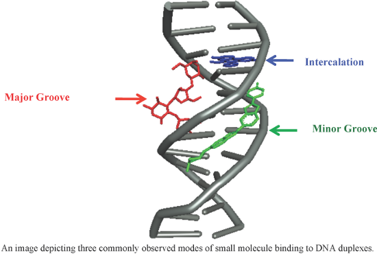
- the past few years. Keywords: alkylators; antibiotic; anticancer; antineoplastic; antiproliferative; DNA recognition; groove binders; hairpin polyamides; Hoechst 33258; intercalators; Review 1. Introduction DNA is one of the central components of cellular machinery and storage unit of genetic
- fashion, they further reported a series of novel hybrids by tethering distamycin A with the antineoplastic agent uramustine via a flexible polymethylene chain of variable length (n = 1 to 6) in order to test their DNA binding affinity and cytotoxicity [57]. It has been observed that hybrid conjugates 8, 9

Graphical Abstract

Figure 1: A figure showing the hydrogen bonding patterns observed in (a) duplex (b) triplex and (c) quadruple...

Figure 2: (a) Portions of MATα1–MATα2 are shown contacting the minor groove of the DNA substrate. Key arginin...

Figure 3: Chemical structures of naturally occurring and synthetic hybrid minor groove binders.

Figure 4: Synthetic structural analogs of distamycin A by replacing one or more pyrrole rings with other hete...

Figure 5: Pictorial representation of the binding model of pyrrole–imidazole (Py/Im) polyamides based on the ...

Figure 6: Chemical structures of synthetic “hairpin” pyrrole–imidazole (Py/Im) conjugates.

Figure 7: (a) Minor groove complex formation between DNA duplex and 8-ring cyclic Py/Im polyamide (conjugate ...

Figure 8: Telomere-targeting tandem hairpin Py/Im polyamides 23 and 24 capable of recognizing >10 base pairs; ...

Figure 9: Representative examples of recently developed DNA minor groove binders.

Figure 10: Chemical structures of bisbenzamidazoles Hoechst 33258 and 33342 and their synthetic structural ana...

Figure 11: Chemical structures of bisamidines such as diminazene, DAPI, pentamidine and their synthetic struct...

Figure 12: Representative examples of recently developed bisamidine derivatives.

Figure 13: Chemical structures of chromomycin, mithramycin and their synthetic structural analogs 91 and 92.

Figure 14: Chemical structures of well-known naturally occurring DNA binding intercalators.

Figure 15: Naturally occurring indolocarbazole rebeccamycin and its synthetic analogs.

Figure 16: Representative examples of naturally occurring and synthetic derivatives of DNA intercalating agent...

Figure 17: Several recent synthetic varieties of DNA intercalators.

Figure 18: Aminoglycoside (neomycin)–Hoechst 33258/intercalator conjugates.

Figure 19: Chemical structures of triazole linked neomycin dimers and neomycin–bisbenzimidazole conjugates.

Figure 20: Representative examples of naturally occurring and synthetic analogs of DNA binding alkylating agen...

Figure 21: Chemical structures of naturally occurring and synthetic analogs of pyrrolobenzodiazepines.
Superstructures with cyclodextrins: Chemistry and applications IV
- Gerhard Wenz
Beilstein J. Org. Chem. 2017, 13, 2157–2159, doi:10.3762/bjoc.13.215

- nanoparticles with the sensitizer Zn-phthalocyanine and the antineoplastic drug docetaxel. These materials might be applicable for dual cancer therapy [15]. Another self-assembled CD nanocarrier for the photoreactive dye squaraine that is useful for photodynamic therapy is described in this Thematic Series [16
Strategies in megasynthase engineering – fatty acid synthases (FAS) as model proteins
- Manuel Fischer and
- Martin Grininger
Beilstein J. Org. Chem. 2017, 13, 1204–1211, doi:10.3762/bjoc.13.119

- antineoplastic doxorubicin and by the antiparasitic avermectin (Figure 1a) [1]. PK are assembled from acyl-coenzyme A (acyl-CoA) units via a series of Claisen-type condensation reactions catalyzed by polyketide synthases (PKS) (Figure 1b). PKS occur as large multifunctional enzymes, termed megasynthases, which

Graphical Abstract

Figure 1: Megasynthases – chemistry and modes of action. a) Products of PKS and FAS megasynthases. b) Reactio...

Figure 2: Compartmentalization of synthesis. a) Surface depiction of fungal FAS (PDB-code: 3hmj) with the upp...

Figure 3: Strategies of megasynthase engineering. a) Mix-and-match approach: A hypothetical chimeric PKS is a...

Figure 4: Preserve-and-adapt approach with FAS. C. ammoniagenes FAS has been engineered in two cooperatively ...
Isoxazole derivatives as new nitric oxide elicitors in plants
- Anca Oancea,
- Emilian Georgescu,
- Florentina Georgescu,
- Alina Nicolescu,
- Elena Iulia Oprita,
- Catalina Tudora,
- Lucian Vladulescu,
- Marius-Constantin Vladulescu,
- Florin Oancea and
- Calin Deleanu
Beilstein J. Org. Chem. 2017, 13, 659–664, doi:10.3762/bjoc.13.65

- ]. The thiophene is a core system of a large number of bioactive molecules such as antineoplastic agents [49], non-steroidal anti-inflammatory drugs [50] or compounds with antibacterial activities against several Gram-positive strains [51]. Thus, 3,5-disubstituted isoxazole derivatives were obtained by

Graphical Abstract

Scheme 1: Synthetic route to 3,5-disubstituted isoxazoles.
N-Propargylamines: versatile building blocks in the construction of thiazole cores
- S. Arshadi,
- E. Vessally,
- L. Edjlali,
- R. Hosseinzadeh-Khanmiri and
- E. Ghorbani-Kalhor
Beilstein J. Org. Chem. 2017, 13, 625–638, doi:10.3762/bjoc.13.61

- prevent gout flare-ups [5][6][7]. Ritonavir (norvir), is an HIV protease inhibitor. It works by blocking the growth of HIV [8][9]. Tiazofurin is a C-nucleoside analogue with antineoplastic activity and acts by inhibition of the guanosine triphosphate (GTP) biosynthesis through a reduction of PI and PIP

Graphical Abstract

Figure 1: Selected examples of bioactive thiazole derivatives.

Figure 2: Some natural sources of thiazoles.

Figure 3: Some important thiazole-based compounds derived from N-propargylamines.

Scheme 1: The synthesis of thiazole-2-thiones 3 through the thermal cyclocondensation of N-propargylamines 1 ...

Scheme 2: (a) One-pot synthesis of 2-benzylthiazolo[3,2-a]benzimidazoles 6 through a base-catalyzed cascade r...

Scheme 3: (a) Synthesis of 2-iminothiazolidines 11 from N-propargylamines 9 and isothiocyanates 10. (b) Synth...

Scheme 4: (a) Synthesis of 2-aminothiazoles 17 through the reaction of ethyl 4-aminobut-2-ynoate salts 15 wit...

Scheme 5: Synthesis of 5-(iodomethylene)-3-methylthiazolidines 27 described by Zhou.

Scheme 6: Mechanism that accounts for the formation of 27.

Scheme 7: Clausen’s synthesis of fluorescein thiazolidines 30.

Scheme 8: Synthesis of multiply substituted thiazolidines 33 from N-propargylamines 32 and blocked N-isothioc...

Scheme 9: (a) Microwave-assisted cyclization of N-propargyl thiocarbamate 34. (b) Synthesis of thiazoles 39 t...

Scheme 10: Synthesis of thiazolidines 42 (42’) from the reaction of β-oxodithioesters 40 (40’) with N-propargy...

Scheme 11: Synthesis of 5-(dibromomethyl)thiazoles 44 via halocyclization of N-propargylamines 43 described by...

Scheme 12: Synthesis of dihydrothiazoles 46 through the treatment of N-propargylamides 45 with Lawesson’s reag...

Scheme 13: Synthesis of thiazoles 49 by treatment of silyl-protected N-propargylamines 47 with benzotriazolylt...

Scheme 14: Mechanism proposed to explain the synthesis of 2,5-disubstituted thiazoles 49 developed by Sasmal.

Scheme 15: Mo-catalyzed cyclization of N-propargylthiocarbamate 50.

Scheme 16: (a) DABCO-mediated intramolecular cyclization of N-(propargylcarbamothioyl)amides 53 to the corresp...

Scheme 17: Proposed mechanism for the generation of the iodine-substituted 4H-1,3-thiazines 56 and 4,5-dihydro...

Scheme 18: Au(III)-catalyzed synthesis of 5-alkylidenedihydrothiazoles 58 developed by Stevens.
Unconventional application of the Mitsunobu reaction: Selective flavonolignan dehydration yielding hydnocarpins
- Guozheng Huang,
- Simon Schramm,
- Jörg Heilmann,
- David Biedermann,
- Vladimír Křen and
- Michael Decker
Beilstein J. Org. Chem. 2016, 12, 662–669, doi:10.3762/bjoc.12.66

- -methoxyhydnocarpin has been described to enhance the antimicrobial activity of berberine [19]. In the light of steadily growing antibiotic resistance any potent and nontoxic MDR inhibitor is of utmost importance. Hydnocarpin has also antineoplastic activity due to sensitizing multidrug-resistant cancer cell lines

Graphical Abstract

Figure 1: Structures of silibinin, isosilybin, and silychristin, and hydnocarpin-type flavonolignans.

Figure 2: Synthetic strategy of semi-synthesis of hydnocarpins from silybins [22].

Scheme 1: Synthesis of ester derivatives of silibinin and conversion to hydnocarpin-type compounds. Reaction ...

Figure 3: Putative mechanism of dehydration of flavanonols under Mitsunobu conditions.

Scheme 2: Attempt to dehydrate catechin. Reagents and conditions: a) p-nitrobenzoic acid, Ph3P, DIAD, THF, rt...

Scheme 3: Preparation of hydnocarpin (4) and isohydnocarpin (6) and attempt to dehydrate silydianin A (11). R...
Synthesis of cyclic N1-pentylinosine phosphate, a new structurally reduced cADPR analogue with calcium-mobilizing activity on PC12 cells
- Ahmed Mahal,
- Stefano D’Errico,
- Nicola Borbone,
- Brunella Pinto,
- Agnese Secondo,
- Valeria Costantino,
- Valentina Tedeschi,
- Giorgia Oliviero,
- Vincenzo Piccialli and
- Gennaro Piccialli
Beilstein J. Org. Chem. 2015, 11, 2689–2695, doi:10.3762/bjoc.11.289

- synthetic building blocks towards the synthesis of biologically relevant compounds such as antiviral and antineoplastic drugs [3][4][5][6][7][8], antibiotics and antifungal agents [9][10][11]. Furthermore, several NNs act as potent second messengers involved in the regulation of key metabolic pathways [12

Graphical Abstract

Figure 1: Structures of cADPR (1), cIDPR (2), cpIDP (3) and cpIMP (4).

Figure 2: Synthetic strategies explored in the cyclization step via phosphodiester bond formation.

Scheme 1: i) (iPr)2NP(OCE)Cl, DIPEA, THF, 1 h, rt; ii) 1) 1H-tetrazole, THF, 2) t-BuOOH, 2 h, rt; iii) 1) (iP...

Scheme 2: i) DNCB, K2CO3, DMF, 4 h, 80 °C; ii) 5-aminopentan-1-ol, DMF, 16 h, 50 °C; iii) Ac2O, pyridine, 2 h...

Figure 3: Effect of 3 and 4 on intracellular [Ca2+] in NGF-differentiated PC12 cells. (A) and (B): representa...
Versatile synthesis and biological evaluation of novel 3’-fluorinated purine nucleosides
- Hang Ren,
- Haoyun An,
- Paul J. Hatala,
- William C. Stevens Jr,
- Jingchao Tao and
- Baicheng He
Beilstein J. Org. Chem. 2015, 11, 2509–2520, doi:10.3762/bjoc.11.272

- ’-fluoro-adenosine 1 in 93% yield. We targeted 9-(3-deoxy-3-fluoro-β-D-ribofuranosyl)purine (1) in particular because it is the 3’-fluorine analogue of nebularine, a naturally occurring antibacterial and antineoplastic agent [42][43]. 3’-Fluoro-6-methylpurine riboside 4, a 6-β-D-MPR mimic 6-Methylpurine-β
- -chloro-intermediates 26 and 48, followed by deprotection, resulted in 6-deaminopurine nucleosides 1 and 21, new analogues of the naturally isolated antibacterial and antineoplastic agent 6-deaminoadenosine, nebularine. Newly synthesized compounds were evaluated for their antitumor activity. Eleven

Graphical Abstract

Figure 1: 6-Subsituted purine 3’-deoxy-3’-fluororibosides 1–15.

Figure 2: 2-Chloro- and 2-aminopurine 3’-deoxy-3’-fluororibosides 16–23.

Figure 3: 3’-Deoxy-3’-fluororibosides constructed from universal intermediate 25.

Scheme 1: Synthesis of 3’-deoxy-3’-fluoropurine ribosides 1–3.

Scheme 2: Synthesis of 6-methylpurine 3’-deoxy-3’-fluororiboside 4.

Scheme 3: Synthesis of 6-substituted purine 3’-deoxy-3’-fluororibosides 5–15.

Scheme 4: Synthesis of 6-substituted 2-chloropurine 3’-deoxy-3’-fluororibosides 16–20.

Scheme 5: Synthesis of 2-aminopurine 3’-deoxy-3’-fluororibosides 21–23.
Dicarboxylic esters: Useful tools for the biocatalyzed synthesis of hybrid compounds and polymers
- Ivan Bassanini,
- Karl Hult and
- Sergio Riva
Beilstein J. Org. Chem. 2015, 11, 1583–1595, doi:10.3762/bjoc.11.174

- in the esterification of the antineoplastic antibiotics mithramycin (5) catalyzed by Candida antarctica lipase A (CAL-A) and chromomycin A3 (6) catalyzed by Candida antarctica lipase B (CAL-B) [24]. In another report a series of mono-substituted troxerutin esters (7a) were synthesized by action of

Graphical Abstract

Scheme 1: Activated derivatives of dicarboxylic acids.

Figure 1: Example of natural compounds selectively acylated with dicarboxylic esters.

Figure 2: C6-dicarboxylic acid diesters derivatives of NAG-thiazoline.

Figure 3: Sylibin dimers obtained by CAL-B catalyzed trans-acylation reactions.

Scheme 2: Biocatalyzed synthesis of paclitaxel derivatives.

Figure 4: 5-Fluorouridine derivatives obtained by CAL-B catalysis.

Scheme 3: Biocatalyzed synthesis of hybrid diesters 17 and 18.

Scheme 4: Hybrid derivatives of sylibin.

Figure 5: Bolaamphiphilic molecules containing (L)- and/or (D)-isoascorbic acid moieties.

Figure 6: Doxorubicin (29) trapped in a polyester made of glycolate, sebacate and 1,4-butandiol units.

Figure 7: Polyesters containing functionalized pentofuranose derivatives.

Figure 8: Polyesters containing disulfide moieties.

Figure 9: Polyesters containing epoxy moieties.

Figure 10: Biocatalyzed synthesis of polyesters containing glycerol.

Figure 11: Iataconic (34) and malic (35) acid.

Figure 12: Oxidized poly(hexanediol-2-mercaptosuccinate) polymer.

Figure 13: C-5-substituted isophthalates.

Figure 14: Curcumin-based polyesters.

Figure 15: Silylated polyesters.

Figure 16: Polyesters containing reactive ether moieties.

Figure 17: Polyesters obtained by CAL-B-catalyzed condensation of dicarboxylic esters and N-substituted dietha...

Figure 18: Polyesters comprising mexiletine (38) moieties.

Figure 19: Poly(amide-co-ester)s comprising a terminal hydroxy moiety.

Figure 20: Polymer comprising α-oxydiacid moieties.

Figure 21: Telechelics with methacrylate ends.

Figure 22: Telechelics with allyl-ether ends.

Figure 23: Telechelics with ends functionalized as epoxides.
DBU-promoted carboxylative cyclization of o-hydroxy- and o-acetamidoacetophenone
- Wen-Zhen Zhang,
- Si Liu and
- Xiao-Bing Lu
Beilstein J. Org. Chem. 2015, 11, 906–912, doi:10.3762/bjoc.11.102

- [4]. Roquinimex was reported as an antineoplastic agent [5]. Traditional methods for accessing these compounds rely heavily on cyclization reactions using diethyl carbonate in the presence of inorganic bases [6][7] or Friedel–Crafts reactions using strong and corrosive acids [8]. In terms of

Graphical Abstract

Figure 1: Selected examples for biologically active 4-hydroxy-2H-chromen-2-one and 4-hydroxy-2(1H)-quinolinon...

Scheme 1: Possible mechanism for the carboxylative cyclization of o-acetamidoacetophenone.

Scheme 2: Cross carboxylative cyclization reaction.
Olefin cross metathesis based de novo synthesis of a partially protected L-amicetose and a fully protected L-cinerulose derivative
- Bernd Schmidt and
- Sylvia Hauke
Beilstein J. Org. Chem. 2014, 10, 1023–1031, doi:10.3762/bjoc.10.102

- antibiotic is aclacinomycin A, which has been used clinically under the name aclarubicin. It is an anthracycline [10] bearing a trisaccharide side chain consisting of L-rhodosamin, 2,6-didesoxy-L-lyxose, and L-cinerulose attached to the aglycon aclavinon [11][12]. It was found to be a potent antineoplastic
- apparently identical catalysts which are often designated just as “10 wt % Pd on carbon” may vary dramatically. Structures of kigamicin B and aclacinomycin A as representative examples for antineoplastic glycoconjugates. RCM-isomerization approach to L-amicetal 4 and alternative CM approaches to L-amicetose

Graphical Abstract

Figure 1: Structures of kigamicin B and aclacinomycin A as representative examples for antineoplastic glycoco...

Scheme 1: RCM-isomerization approach to L-amicetal 4 and alternative CM approaches to L-amicetose.

Scheme 2: Two step desilylation–acetal hydrolysis.

Scheme 3: Deprotection of 11 and 12 to L-amicetose derivative 16.

Scheme 4: Synthesis of a cinerulose-TBS ether 22.

Scheme 5: Deprotection of 24.
An overview of the synthetic routes to the best selling drugs containing 6-membered heterocycles
- Marcus Baumann and
- Ian R. Baxendale
Beilstein J. Org. Chem. 2013, 9, 2265–2319, doi:10.3762/bjoc.9.265


Graphical Abstract

Scheme 1: Scaled industrial processes for the synthesis of simple pyridines.

Scheme 2: Synthesis of nicotinic acid from 2-methyl-5-ethylpyridine (1.11).

Scheme 3: Synthesis of 3-picoline and nicotinic acid.

Scheme 4: Synthesis of 3-picoline from 2-methylglutarodinitrile 1.19.

Scheme 5: Picoline-based synthesis of clarinex (no yields reported).

Scheme 6: Mode of action of proton-pump inhibitors and structures of the API’s.

Scheme 7: Hantzsch-like route towards the pyridine rings in common proton pump inhibitors.

Figure 1: Structures of rosiglitazone (1.40) and pioglitazone (1.41).

Scheme 8: Synthesis of rosiglitazone.

Scheme 9: Syntheses of 2-pyridones.

Scheme 10: Synthesis and mechanism of 2-pyrone from malic acid.

Scheme 11: Polymer-assisted synthesis of rosiglitazone.

Scheme 12: Synthesis of pioglitazone.

Scheme 13: Meerwein arylation reaction towards pioglitazone.

Scheme 14: Route towards pioglitazone utilising tyrosine.

Scheme 15: Route towards pioglitazone via Darzens ester formation.

Scheme 16: Syntheses of the thiazolidinedione moiety.

Scheme 17: Synthesis of etoricoxib utilising Negishi and Stille cross-coupling reactions.

Scheme 18: Synthesis of etoricoxib via vinamidinium condensation.

Figure 2: Structures of nalidixic acid, levofloxacin and moxifloxacin.

Scheme 19: Synthesis of moxifloxacin.

Scheme 20: Synthesis of (S,S)-2,8-diazabicyclo[4.3.0]nonane 1.105.

Scheme 21: Synthesis of levofloxacin.

Scheme 22: Alternative approach to the levofloxacin core 1.125.

Figure 3: Structures of nifedipine, amlodipine and clevidipine.

Scheme 23: Mg3N2-mediated synthesis of nifedipine.

Scheme 24: Synthesis of rac-amlodipine as besylate salt.

Scheme 25: Aza Diels–Alder approach towards amlodipine.

Scheme 26: Routes towards clevidipine.

Figure 4: Examples of piperidine containing drugs.

Figure 5: Discovery of tiagabine based on early leads.

Scheme 27: Synthetic sequences to tiagabine.

Figure 6: Structures of solifenacin (2.57) and muscarine (2.58).

Scheme 28: Enantioselective synthesis of solifenacin.

Figure 7: Structures of DPP-4 inhibitors of the gliptin-type.

Scheme 29: Formation of inactive diketopiperazines from cis-rotameric precursors.

Figure 8: Co-crystal structure of carmegliptin bound in the human DPP-4 active site (PDB 3kwf).

Scheme 30: Improved route to carmegliptin.

Figure 9: Structures of lamivudine and zidovudine.

Scheme 31: Typical routes accessing uracil, thymine and cytosine.

Scheme 32: Coupling between pyrimidones and riboses via the Vorbrüggen nucleosidation.

Scheme 33: Synthesis of lamivudine.

Scheme 34: Synthesis of raltegravir.

Scheme 35: Mechanistic studies on the formation of 3.22.

Figure 10: Structures of selected pyrimidine containing drugs.

Scheme 36: General preparation of pyrimidines and dihydropyrimidones.

Scheme 37: Synthesis of imatinib.

Scheme 38: Flow synthesis of imatinib.

Scheme 39: Syntheses of erlotinib.

Scheme 40: Synthesis of erlotinib proceeding via Dimroth rearrangement.

Scheme 41: Synthesis of lapatinib.

Scheme 42: Synthesis of rosuvastatin.

Scheme 43: Alternative preparation of the key aldehyde towards rosuvastatin.

Figure 11: Structure comparison between nicotinic acetylcholine receptor agonists.

Scheme 44: Syntheses of varenicline and its key building block 4.5.

Scheme 45: Synthetic access to eszopiclone and brimonidine via quinoxaline intermediates.

Figure 12: Bortezomib bound in an active site of the yeast 20S proteasome ([114], pdb 2F16).

Scheme 46: Asymmetric synthesis of bortezomib.

Figure 13: Structures of some prominent piperazine containing drugs.

Figure 14: Structural comparison between the core of aplaviroc (4.35) and a type-1 β-turn (4.36).

Scheme 47: Examplary synthesis of an aplaviroc analogue via the Ugi-MCR.

Scheme 48: Syntheses of azelastine (5.1).

Figure 15: Structures of captopril, enalapril and cilazapril.

Scheme 49: Synthesis of cilazapril.

Figure 16: Structures of lamotrigine, ceftriaxone and azapropazone.

Scheme 50: Synthesis of lamotrigine.

Scheme 51: Alternative synthesis of lamotrigine (no yields reported).

Figure 17: Structural comparison between imiquimod and the related adenosine nucleoside.

Scheme 52: Conventional synthesis of imiquimod (no yields reported).

Scheme 53: Synthesis of imiquimod.

Scheme 54: Synthesis of imiquimod via tetrazole formation (not all yields reported).

Figure 18: Structures of various anti HIV-medications.

Scheme 55: Synthesis of abacavir.

Figure 19: Structures of diazepam compared to modern replacements.

Scheme 56: Synthesis of ocinaplon.

Scheme 57: Access to zaleplon and indiplon.

Scheme 58: Different routes towards the required N-methylpyrazole 6.65 of sildenafil.

Scheme 59: Polymer-supported reagents in the synthesis of key aminopyrazole 6.72.

Scheme 60: Early synthetic route to sildenafil.

Scheme 61: Convergent preparations of sildenafil.

Figure 20: Comparison of the structures of sildenafil, tadalafil and vardenafil.

Scheme 62: Short route to imidazotriazinones.

Scheme 63: Alternative route towards vardenafils core imidazotriazinone (6.95).

Scheme 64: Bayer’s approach to the vardenafil core.

Scheme 65: Large scale synthesis of vardenafil.

Scheme 66: Mode of action of temozolomide (6.105) as methylating agent.

Scheme 67: Different routes to temozolomide.

Scheme 68: Safer route towards temozolomide.

Figure 21: Some unreported heterocyclic scaffolds in top market drugs.
Engineering of indole-based tethered biheterocyclic alkaloid meridianin into β-carboline-derived tetracyclic polyheterocycles via amino functionalization/6-endo cationic π-cyclization
- Piyush K. Agarwal,
- Meena D. Dathi,
- Mohammad Saifuddin and
- Bijoy Kundu
Beilstein J. Org. Chem. 2012, 8, 1901–1908, doi:10.3762/bjoc.8.220

- in the literature. β-Carbolines are some of the most widely distributed alkaloids, associated with activities ranging from antineoplastic (tubulin binding) [44][45][46], anticonvulsive, hypnotic and anxiolytic (benzodiazepine receptor ligands) [47], antimicrobial as well as topoisomerase-II

Graphical Abstract

Figure 1: Structure of meridianins A–G.

Scheme 1: Synthesis of functionalized meridianin with an amino group at position 5.

Scheme 2: Synthesis of a functionalized meridianin with an amino group at position 5.

Scheme 3: Synthesis of substrate for the modified Pictet–Spengler reaction.

Scheme 4: The Pictet–Spengler reaction involving substrate 2a. Reagents and conditions: (i) RCHO, 2% triflic ...

Scheme 5: Synthesis of dihydropyrimido-β-carbolines: (i) R-CHO, 2% triflic acid in DMF, 120 °C, 16 h.

Scheme 6: Synthesis of substrates 18a–c for the modified Pictet–Spengler reaction.

Scheme 7: General strategy for the Pictet–Spengler reaction involving substrates 18. Reagents and conditions:...
Directed aromatic functionalization in natural-product synthesis: Fredericamycin A, nothapodytine B, and topopyrones B and D
- Charles Dylan Turner and
- Marco A. Ciufolini
Beilstein J. Org. Chem. 2011, 7, 1475–1485, doi:10.3762/bjoc.7.171

- properties of topopyrones are sufficiently interesting that a number of groups embarked on a total synthesis [94][95][96]. Our own involvement in this area was motivated by an interest in topoisomerase-I inhibitors, which are important antineoplastic resources [97], the archetype of which is camptothecin [81

Graphical Abstract

Scheme 1: Structure and retrosynthetic analysis of fredericamycin A.

Scheme 2: Assembly of the isoquinolone segment of fredericamycin.

Scheme 3: Synthesis of a naphthalide precursor to the quinoid moiety of fredericamycin.

Scheme 4: Palladium-mediated cyclization of a fredericamycin model system.

Scheme 5: Synthesis of the precursor of fredericamycin and the facile air oxidation thereof.

Scheme 6: Formal synthesis of fredericamycin A.

Figure 1: Structure of nothapodytine B.

Scheme 7: A useful pyridone synthesis.

Scheme 8: Retrosynthetic logic for nothapodytine B.

Scheme 9: Preparation of a key nothapodytine fragment.

Scheme 10: Total synthesis of nothapodytine B.

Figure 2: Structures of topopyrones.

Scheme 11: Retrosynthetic logic for the linear series of topopyrones.

Scheme 12: Construction of the molecular subunit common to all topopyrones.

Scheme 13: Difficulties encountered during the merger of the topopyrone D moieties.

Scheme 14: Efficient synthesis of a simplified anthraquinone.

Scheme 15: Total synthesis of topopyrone D.

Scheme 16: Total synthesis of topopyrone B.
Synthesis of some novel hydrazono acyclic nucleoside analogues
- Mohammad N. Soltani Rad,
- Ali Khalafi-Nezhad and
- Somayeh Behrouz
Beilstein J. Org. Chem. 2010, 6, No. 49, doi:10.3762/bjoc.6.49

- antineoplastic (e.g. bisantrene [4][10]), contain a hydrazone moiety in their structure. Furthermore, various structurally related miconazole bioactive hydrazones are known as antimicrobial and antifungal agents [11][12]. The significance of nucleoside chemistry in drug discovery is well-known and fully

Graphical Abstract

Figure 1: Chemical structures of miconazole (A), oxiconazole (B) and hydrazono acyclic nucleoside analogue (C...

Scheme 1: Synthetic pathway for hydrazono acyclic nucleoside 2a–2g.

Scheme 2: Synthetic pathway for hydrazono acyclic nucleoside 2h–2o.