Extension of the 5-alkynyluridine side chain via C–C-bond formation in modified organometallic nucleosides using the Nicholas reaction
- Renata Kaczmarek,
- Dariusz Korczyński,
- James R. Green and
- Roman Dembinski
Beilstein J. Org. Chem. 2020, 16, 1–8, doi:10.3762/bjoc.16.1


Synthesis of C-glycosyl phosphonate derivatives of 4-amino-4-deoxy-α-ʟ-arabinose
- Lukáš Kerner and
- Paul Kosma
Beilstein J. Org. Chem. 2020, 16, 9–14, doi:10.3762/bjoc.16.2


Functionalization of the imidazo[1,2-a]pyridine ring in α-phosphonoacrylates and α-phosphonopropionates via microwave-assisted Mizoroki–Heck reaction
- Damian Kusy,
- Agata Wojciechowska,
- Joanna Małolepsza and
- Katarzyna M. Błażewska
Beilstein J. Org. Chem. 2020, 16, 15–21, doi:10.3762/bjoc.16.3


Starazo triple switches – synthesis of unsymmetrical 1,3,5-tris(arylazo)benzenes
- Andreas H. Heindl and
- Hermann A. Wegner
Beilstein J. Org. Chem. 2020, 16, 22–31, doi:10.3762/bjoc.16.4


Microwave-assisted synthesis of 2-substituted 4,5,6,7-tetrahydro-1,3-thiazepines from 4-aminobutanol
- María C. Mollo,
- Natalia B. Kilimciler,
- Juan A. Bisceglia and
- Liliana R. Orelli
Beilstein J. Org. Chem. 2020, 16, 32–38, doi:10.3762/bjoc.16.5


Light-controllable dithienylethene-modified cyclic peptides: photoswitching the in vivo toxicity in zebrafish embryos
- Sergii Afonin,
- Oleg Babii,
- Aline Reuter,
- Volker Middel,
- Masanari Takamiya,
- Uwe Strähle,
- Igor V. Komarov and
- Anne S. Ulrich
Beilstein J. Org. Chem. 2020, 16, 39–49, doi:10.3762/bjoc.16.6


Understanding the role of active site residues in CotB2 catalysis using a cluster model
- Keren Raz,
- Ronja Driller,
- Thomas Brück,
- Bernhard Loll and
- Dan T. Major
Beilstein J. Org. Chem. 2020, 16, 50–59, doi:10.3762/bjoc.16.7


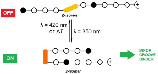
Photocontrolled DNA minor groove interactions of imidazole/pyrrole polyamides
- Sabrina Müller,
- Jannik Paulus,
- Jochen Mattay,
- Heiko Ihmels,
- Veronica I. Dodero and
- Norbert Sewald
Beilstein J. Org. Chem. 2020, 16, 60–70, doi:10.3762/bjoc.16.8


The interaction between cucurbit[8]uril and baicalein and the effect on baicalein properties
- Xiaodong Zhang,
- Jun Xie,
- Zhiling Xu,
- Zhu Tao and
- Qianjun Zhang
Beilstein J. Org. Chem. 2020, 16, 71–77, doi:10.3762/bjoc.16.9


Halogen-bonding-induced diverse aggregation of 4,5-diiodo-1,2,3-triazolium salts with different anions
- Xingyu Xu,
- Shiqing Huang,
- Zengyu Zhang,
- Lei Cao and
- Xiaoyu Yan
Beilstein J. Org. Chem. 2020, 16, 78–87, doi:10.3762/bjoc.16.10


[1,3]/[1,4]-Sulfur atom migration in β-hydroxyalkylphosphine sulfides
- Katarzyna Włodarczyk,
- Piotr Borowski and
- Marek Stankevič
Beilstein J. Org. Chem. 2020, 16, 88–105, doi:10.3762/bjoc.16.11


Convenient synthesis of the pentasaccharide repeating unit corresponding to the cell wall O-antigen of Escherichia albertii O4
- Tapasi Manna,
- Arin Gucchait and
- Anup Kumar Misra
Beilstein J. Org. Chem. 2020, 16, 106–110, doi:10.3762/bjoc.16.12


Reversible photoswitching of the DNA-binding properties of styrylquinolizinium derivatives through photochromic [2 + 2] cycloaddition and cycloreversion
- Sarah Kölsch,
- Heiko Ihmels,
- Jochen Mattay,
- Norbert Sewald and
- Brian O. Patrick
Beilstein J. Org. Chem. 2020, 16, 111–124, doi:10.3762/bjoc.16.13


Potent hemithioindigo-based antimitotics photocontrol the microtubule cytoskeleton in cellulo
- Alexander Sailer,
- Franziska Ermer,
- Yvonne Kraus,
- Rebekkah Bingham,
- Ferdinand H. Lutter,
- Julia Ahlfeld and
- Oliver Thorn-Seshold
Beilstein J. Org. Chem. 2020, 16, 125–134, doi:10.3762/bjoc.16.14


Rapid, two-pot procedure for the synthesis of dihydropyridinones; total synthesis of aza-goniothalamin
- Thomas J. Cogswell,
- Craig S. Donald and
- Rodolfo Marquez
Beilstein J. Org. Chem. 2020, 16, 135–139, doi:10.3762/bjoc.16.15


Synthesis of 3-alkenylindoles through regioselective C–H alkenylation of indoles by a ruthenium nanocatalyst
- Abhijit Paul,
- Debnath Chatterjee,
- Srirupa Banerjee and
- Somnath Yadav
Beilstein J. Org. Chem. 2020, 16, 140–148, doi:10.3762/bjoc.16.16


Synthesis, liquid crystalline behaviour and structure–property relationships of 1,3-bis(5-substituted-1,3,4-oxadiazol-2-yl)benzenes
- Afef Mabrouki,
- Malek Fouzai,
- Armand Soldera,
- Abdelkader Kriaa and
- Ahmed Hedhli
Beilstein J. Org. Chem. 2020, 16, 149–158, doi:10.3762/bjoc.16.17


The reaction of arylmethyl isocyanides and arylmethylamines with xanthate esters: a facile and unexpected synthesis of carbamothioates
- Narasimhamurthy Rajeev,
- Toreshettahally R. Swaroop,
- Ahmad I. Alrawashdeh,
- Shofiur Rahman,
- Abdullah Alodhayb,
- Seegehalli M. Anil,
- Kuppalli R. Kiran,
- Chandra,
- Paris E. Georghiou,
- Kanchugarakoppal S. Rangappa and
- Maralinganadoddi P. Sadashiva
Beilstein J. Org. Chem. 2020, 16, 159–167, doi:10.3762/bjoc.16.18


Efficient method for propargylation of aldehydes promoted by allenylboron compounds under microwave irradiation
- Jucleiton J. R. Freitas,
- Queila P. S. B. Freitas,
- Silvia R. C. P. Andrade,
- Juliano C. R. Freitas,
- Roberta A. Oliveira and
- Paulo H. Menezes
Beilstein J. Org. Chem. 2020, 16, 168–174, doi:10.3762/bjoc.16.19


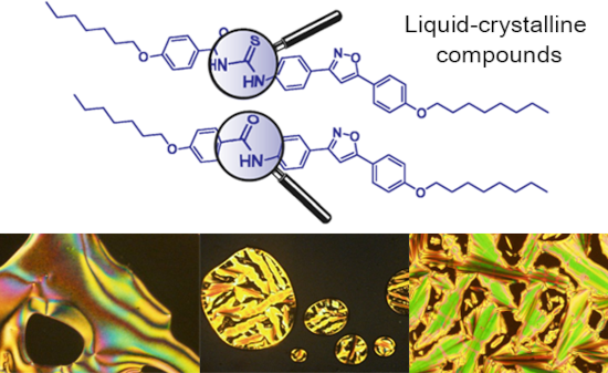
The use of isoxazoline and isoxazole scaffolding in the design of novel thiourea and amide liquid-crystalline compounds
- Itamar L. Gonçalves,
- Rafaela R. da Rosa,
- Vera L. Eifler-Lima and
- Aloir A. Merlo
Beilstein J. Org. Chem. 2020, 16, 175–184, doi:10.3762/bjoc.16.20


Allylic cross-coupling using aromatic aldehydes as α-alkoxyalkyl anions
- Akihiro Yuasa,
- Kazunori Nagao and
- Hirohisa Ohmiya
Beilstein J. Org. Chem. 2020, 16, 185–189, doi:10.3762/bjoc.16.21


Synthesis of 4-(2-fluorophenyl)-7-methoxycoumarin: experimental and computational evidence for intramolecular and intermolecular C–F···H–C bonds
- Vuyisa Mzozoyana,
- Fanie R. van Heerden and
- Craig Grimmer
Beilstein J. Org. Chem. 2020, 16, 190–199, doi:10.3762/bjoc.16.22


Combination of multicomponent KA2 and Pauson–Khand reactions: short synthesis of spirocyclic pyrrolocyclopentenones
- Riccardo Innocenti,
- Elena Lenci,
- Gloria Menchi and
- Andrea Trabocchi
Beilstein J. Org. Chem. 2020, 16, 200–211, doi:10.3762/bjoc.16.23


Copper-catalyzed enantioselective conjugate addition of organometallic reagents to challenging Michael acceptors
- Delphine Pichon,
- Jennifer Morvan,
- Christophe Crévisy and
- Marc Mauduit
Beilstein J. Org. Chem. 2020, 16, 212–232, doi:10.3762/bjoc.16.24


Synthesis and herbicidal activities of aryloxyacetic acid derivatives as HPPD inhibitors
- Man-Man Wang,
- Hao Huang,
- Lei Shu,
- Jian-Min Liu,
- Jian-Qiu Zhang,
- Yi-Le Yan and
- Da-Yong Zhang
Beilstein J. Org. Chem. 2020, 16, 233–247, doi:10.3762/bjoc.16.25


Recent developments in photoredox-catalyzed remote ortho and para C–H bond functionalizations
- Rafia Siddiqui and
- Rashid Ali
Beilstein J. Org. Chem. 2020, 16, 248–280, doi:10.3762/bjoc.16.26


Ultrasonic-assisted unusual four-component synthesis of 7-azolylamino-4,5,6,7-tetrahydroazolo[1,5-a]pyrimidines
- Yana I. Sakhno,
- Maryna V. Murlykina,
- Oleksandr I. Zbruyev,
- Anton V. Kozyryev,
- Svetlana V. Shishkina,
- Dmytro Sysoiev,
- Vladimir I. Musatov,
- Sergey M. Desenko and
- Valentyn A. Chebanov
Beilstein J. Org. Chem. 2020, 16, 281–289, doi:10.3762/bjoc.16.27


Absolute configurations of talaromycones A and B, α-diversonolic ester, and aspergillusone B from endophytic Talaromyces sp. ECN211
- Ken-ichi Nakashima,
- Junko Tomida,
- Takao Hirai,
- Yoshiaki Kawamura and
- Makoto Inoue
Beilstein J. Org. Chem. 2020, 16, 290–296, doi:10.3762/bjoc.16.28


Two antibacterial and PPARα/γ-agonistic unsaturated keto fatty acids from a coral-associated actinomycete of the genus Micrococcus
- Amit Raj Sharma,
- Enjuro Harunari,
- Naoya Oku,
- Nobuyasu Matsuura,
- Agus Trianto and
- Yasuhiro Igarashi
Beilstein J. Org. Chem. 2020, 16, 297–304, doi:10.3762/bjoc.16.29


